Interaction-Shaped Vortex-Antivortex Lattices in Polariton Fluids
Abstract
Topological defects such as quantized vortices are one of the most striking manifestations of the superfluid nature of Bose-Einstein condensates and typical examples of quantum mechanical phenomena on a macroscopic scale. Here we demonstrate the formation of a lattice of vortex-antivortex pairs and study, for the first time, its properties in the non-linear regime at high polarion-density where polariton-polariton interactions dominate the behaviour of the system. In this work first we demonstrate that the array of vortex-antivortex pairs can be generated in a controllable way in terms of size of the array and in terms of size and shape of it fundamental unit cell. Then we demonstrate that polariton-polariton repulsion can strongly deform the lattice unit cell and determine the pattern distribution of the vortex-antivortex pairs, reaching a completely new behaviour with respect to geometrically generated vortex lattices whose shape is determined only by the geometry of the system.
pacs:
03.75.Lm, 42.65.Hw, 71.36.+cI Introduction
Quantized vortices are topological excitations characterized by the vanishing of the field density at a given point, the vortex core, and by the quantized winding of the field phase from 0 to around it (with m an integer number). Together with solitons they have been extensively studied onsager_statistical_1949 ; feynman_vol._1955 ; nye_dislocations_1974 and observed in non-linear optical systems desyatnikov_optical_2005 , superconductors essmann_direct_1967 , superfluid 4He yarmchuk_observation_1979 , vertical-cavity surface-emitting lasers scheuer_optical_1999 , and more recently in cold atoms madison_vortex_2000 ; denschlag_generating_2000 ; khaykovich_formation_2002 where, as predicted by Abrikosov abrikosov_magnetic_1957 , vortices tend to arrange in triangular lattices due to their mutual interactions. Finally, in recent years, the study of vortices and vortex lattices has attracted much attention also in the field of coherent light-matter systems.
Semiconductor microcavities can be designed to strongly couple cavity photons to quantum well excitons. The eigenstates of this system are called exciton-polaritons and are characterised by specific properties such as low effective mass, inherited from their photonic component, and strong non-linear interactions due to their excitonic part. Moreover, polaritonic systems are easily controllable by optical techniques and, due to their finite lifetime are ideal systems to study out of equilibrium phenomena deng_exciton-polariton_2010 ; carusotto_quantum_2013 . In analogy with the atomic case dalfovo_theory_1999 ; burger_superfluid_2001 the superfluid behaviour of polaritonic Bose-Einstein condensates kasprzak_boseeinstein_2006 has been of great theoretical interest carusotto_probing_2004 ; wouters_superfluidity_2010 ; cancellieri_superflow_2010 ; cancellieri_frictionless_2012 and has been experimentally confirmed by the suppression of scattering in the case of a polariton fluid flowing past a defect amo_collective_2009 ; amo_superfluidity_2009 and by the persistence of circular quantized currents sanvitto_persistent_2010 . In particular, cavity-polariton systems have been predicted and shown to undergo formation of stable vortices lagoudakis_quantized_2008 and half-vortices lagoudakis_observation_2009 ; flayac_topological_2010 as well as formation of single vortex-antivortex (V-AV) pairs roumpos_single_2011 ; nardin_hydrodynamic_2011 ; tosi_onset_2011 . More recently, Amo et al. amo_polariton_2011 and Hivet et al. hivet_half-solitons_2012 have demonstrated the nucleation of hydrodynamic solitons and half-solitons in resonantly pumped polaritons flowing against an extended obstacle. The formation of lattices of vortex and of vortex-antivortex pairs has been theoretically predicted and experimentally studied for cavity-polaritons gorbach_vortex_2010 ; keeling_spontaneous_2008 ; liew_generation_2008 , and its appearance has been observed in the case of patterns induced by metallic deposition on the surface of the cavity kusudo_stochastic_2012 , and in the case in which the interplay between the excitation shape and the underlying disordered potential is able to pin the position of the vortices allowing their detection in time-integrated experiments manni_2013 .
In the present work, we use a continuous wave laser to resonantly inject polaritons outside of a masked region pigeon_hydrodynamic_2011 and to observe vortex lattices trapped by an optically controllable potential that, at the same time, stimulates the lattice formation. Here, the resonant pumping configuration allows for a fine tuning of the polariton density but does not generate an excitonic reservoir. For this reason, we can address theoretically and observe experimentally, for the first time, the effects of the polariton-polariton non-linear interactions on the shape of the lattice of vortices. This is in contrast with what was possible to observe with an out-of-resonance setup tosi_geometrically_2012 ; cristofolini_optical_2013 . In these latter cases, either the shape of the lattice was completely determined by the geometry of the pumping scheme tosi_geometrically_2012 , or a transition to trapped states was observed by bringing the pump spots closer to each other cristofolini_optical_2013 . In these experiments the excitonic reservoir plays a fundamental role by determining the characteristic length and the shape of the formed vortex arrays, and in generating the potential where the polariton condensate is trapped, leading to the disappearance of the vortex lattice.
The paper is organized in three main sections, in the first section we describe the setup used to perform the experiments, in the second we highlight our main results distinguishing between two main regimes: the linear regime at low polariton densities, and the non-linear regime at high polariton densities. In this section we address ways to control the shape and the size of the generated array and show that a new regime can be reached in which polariton-polariton interactions determine the shape of the array. Finally, in the last section, we derive our conclusions.
II Experimental Setup
In our experiment we use a high finesse GaAs microcavity () with a polariton lifetime ps and a Rabi splitting of 5.1 meV houdre_coherence_2000 ; adrados_motion_2011 ; sanvitto_all-optical_2011 (see Appendix A: Sample description). The microcavity is excited with a continuous-wave single-mode Ti:Sa laser quasi resonant with the lower polariton branch at 837 nm. The pump laser is circularly polarized in order to avoid any effect due to spin-dependent interactions vladimirova_polariton-polariton_2010 . The output beam can be made to interfere with a reference beam of constant phase from the same laser before being collected on a CCD camera, thus allowing for the reconstruction of the phase of the fluid with simple numerical treatment (see Appendix B: Phase extraction procedure). The experimental observations have been performed at 10 K in transmission configuration and for different positions of the laser spot on the cavity that correspond to different exciton-photon detunings , where are the excitonic and photonic energies at normal incidence (, where is the projection of the light wavevector on the plane of the microcavity). In order to observe vortices, it is critical to let the polariton phase evolve freely after they have been injected by the laser. In previous studies polaritons were observed in a region of the microcavity where they have moved away from the laser spot, which was efficiently limited by a mask. This technique, ensuring a free evolution of the phase, allowed for the observation of solitons amo_polariton_2011 , half-solitons hivet_half-solitons_2012 and vortices pigeon_hydrodynamic_2011 .
We focus the laser beam on a metallic gold-coated mask smaller than the beam waist that locally sets the laser intensity to zero. Using masks with different shapes and sizes (such as triangles and squares), it is possible to obtain laser beams with zero intensity regions of different shapes. This partially obscured waist is then imaged on the microcavity therefore creating a polariton fluid outside a dark region whose size and shape can be set at will (fig. 1A). In this experiment the beam waist has a diameter of 110 m with a square dark region in the centre with a side of 45 m, and an energy set above the bare polariton energy at for the considered point on the microcavity. Therefore the laser energy crosses the bare lower polariton dispersion curve at a non-zero value of , (fig. 1B). This crossing has the shape of a ring, corresponding to the Rayleigh ring. Since the beam is set at normal incidence this value of is not present in the laser beam. However, due to the presence of the mask, photons are diffracted with various values of perpendicular to the edges and can enter the cavity when they have the right value. Polaritons then enter into the dark region flowing with four directions perpendicular to the mask edges. When the laser intensity is increased, in the bright region of the spot, the lower polariton branch (LPB) is blue-shifted into resonance with the laser energy at due to the high polariton density (left and right regions of fig. 1C). In the dark region of the spot (central region of fig. 1C) the LPB is not renormalized because the polariton density is low. Therefore, polaritons created at the edge of the bright region can travel into the dark region getting a momentum that conserves their energy wertz_spontaneous_2009 . As in the non resonant excitation case, polaritons flow into the dark region with four directions perpendicular to the mask edges.
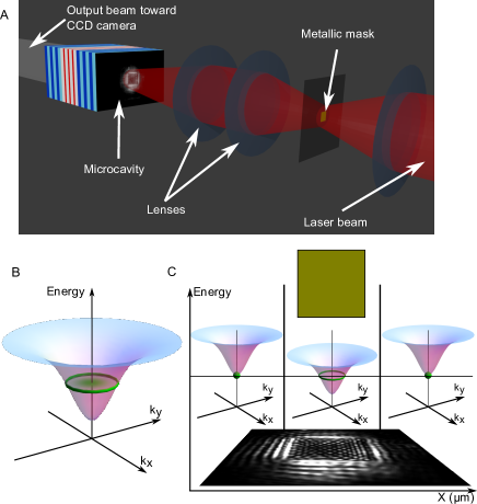
The system being completely symmetric, it is bound to keep a total angular momentum equal to zero and, therefore, the number of generated vortices is bound to be always equal to the number of antivortices. In this sense vortices and antivortices are always generated in pairs although they do not necessarily form bound states. Here vortices and antivortices are characterized by a or rotation of the phase of the wavefunction around the core of the topological defect where the polariton density goes to zero (See inset of fig. 2B).
III Results
In order to better highlight the mechanism lying beneath the formation of the V-AV lattice and the role of polariton-polariton interactions, we study the system as a function of the polariton density. We identify two different regimes: a linear regime at low polariotn density; and a non-linear regime at high polariton density. The linear regime is characterised by the polariton density lying on the lower branch of the bistability curve baas_optical_2004 everywhere in space, and its behaviour is completely linear. The non-linear regime corresponds to a polariton density that is on the upper branch of the bistability curve outside the masked region and that gradually decreases until it reaches the lower branch at the center of the trap. In this regime polariton-polariton interactions dominate the behaviour of the system.
III.1 Linear regime.
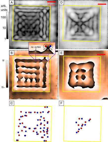
Figure 2A shows the experimental real space distribution of the light transmitted by the cavity when a square mask partially blocks the pumping beam with pump power of 1 mW. The transmitted beam is made to interfere with a reference beam and the phase of the interferogram (fig. 2B) is analysed in details in order to identify the position of the vortices (fig. 2C). Since in this case the laser intensity and the polariton density are low, polariton-polariton interactions play a negligible role and the system is analogous to the case of overlapping laser beams interfering in a medium with linear dispersion. In this first case, where a square mask is used, polaritons mainly flow from the four sides of the mask towards the centre and the polaritonic system corresponds to the case of four plane waves coming from four orthogonal directions. These flows generate an interference pattern with a clearly identifiable wave vector that, from now on, we define as the vortex-lattice characteristic wavevector. However, while for the case of four plane waves only a square interference pattern without any vorticity would appear, here V-AV pairs can form thanks to the non uniform density distribution. The finite lifetime of cavity polaritons, together with the fact that the local polariton density and the local polariton velocity are determined by the sum of the polariton flows coming from the different sides of the mask, induces a non-homogeneous polariton distribution that, in turns, changes the direction of the polariton flows and allows the formation of vortices and antivortices.
Note that while a regular squared interference pattern generated by four plane waves is clearly visible in the experiment (figures 2A and 2B) in the entire masked region, figure 2C shows that there are areas (center and bottom) where vortices and antivortices do not appear. This is mainly due to the unavoidable presence of disorder and defects in the microcavity sample that might inhibit the formation of V-AV pairs; on the other hand if the core of a vortex is very close to the core of an antivortex the experimental resolution in the phase measurements might be insufficient to resolve them. The comparison of these results with the Gross-Pitaevskii based simulations in figure 5 (for more details on the theoretical model see Appendix A) shows that a regular interference pattern, with a characteristic wave vector similar to the one observed in figure 2, is clearly observed also in the numerical simulations, both in the emission intensity map (figure 5A) and in the phase map (figure 5B). Despite these similarities one can see that the actual vortex distribution in figure 5C slightly differs from the one of figure 2C, this is due to the aforementioned imperfections of the real experimental system that can not be entirely reproduced by the simulations.
III.1.1 Control of the size of the unit cell
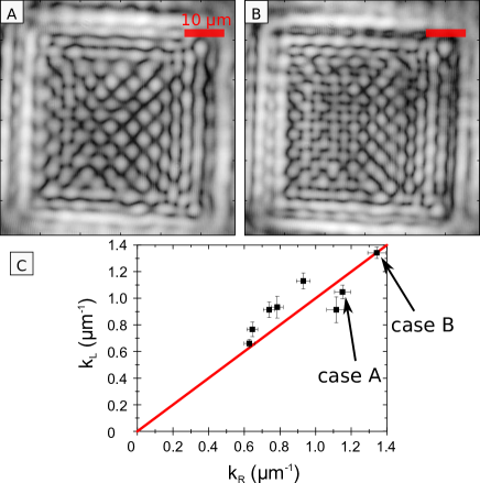
As the of the polaritons flowing into the trap is determined by the detuning between the energy of the pump and the bare LP at normal incidence, a change of the laser frequency allows for a fine tuning of and therefore for the control of the lattice unit cell size: an increase (decrease) of the pump frequency corresponds to an increase (decrease) of the momentum of the injected polaritons and therefore to smaller (larger) size of the unit cell. Figures 3-A and 3-B represent the transmitted light in the same region of the microcavity in the case where only the frequency of the laser has been changed. The increase (from A to B) of the laser frequency results in the increase of the momentum of the injected polaritons and, therefore, in the decrease of the size of the unit-cell. To study the relation between the unit cell size and the laser-LP detuning, we extract, for several detunings, the characteristic wave vector of the lattice and compare it with the -vector of the corresponding Rayleigh ring given by the relation . The results, shown in Figure 3-C, demonstrate a linear dependence between the two -vectors.
III.1.2 Control of the shape of the unit cell
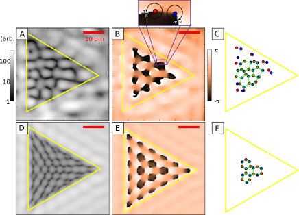
While the of the injected polaritons is governed by the detuning between the laser and the bare LP branch, the direction of the polaritons is determined by the shape of the mask used to block part of the laser spot. Therefore the shape of the unit cell can be controlled by changing the shape of the maks. In the case of a triangular mask (Figure 4), when the laser intensity and the polariton density are low and polariton-polariton interactions play a negligible role, the polaritonic fluid forms an array of vortex-antivortex pairs arranged in a hexagonal unit cell as expected for the superposition of three laser beams masajada_optical_2001 . Figure 4 compares the experimental and theoretical output for a m side almost equilateral triangle and its corresponding phase. In the experimental output we can recognize up to 8-9 unit cells in very good agreement with the Gross-Pitaevskii based simulations. In this regime the generation of the lattice is driven by the interferences between polaritons coming from each side of the triangle and flowing toward the centre of the trap. The result is therefore analogous to the case of three overlapping laser beams interfering in a linear medium. Finally, let us mention that changing the size of the mask for fixed polariton wavevector and fixed mask shape results in a change of the overall lattice size only, while size and shape of the unit cells remain unchanged.
III.2 Non-linear regime.
Figures 2D-F show the experimental polariton distribution in the case of high laser power (pump power has been increased from 1 mW to 35 mW) for the same mask, same position in the cavity and same laser frequency as in fig. 2A-C. Comparing the polariton distribution at low density (fig. 2A-C) with the one at higher density (fig. 2D-F) we see a drastic change in the distribution of the topological defects. At high densities, the repulsion between polaritons not only leads to an enlargement and to a deformation of the lattice unit cell, which is mostly due to a blue shift of the polariton energy, but also leads to a drastic change in the vortex distribution. In particular, as discussed below, the disappearence of the vortices from the outer part of the trap is linked to quantum fluid properties of the polariton condensate. This behaviour is remarkably consistent with the theoretical simulations shown in fig. 5D-F for the same set of parameters as in the experimental case.
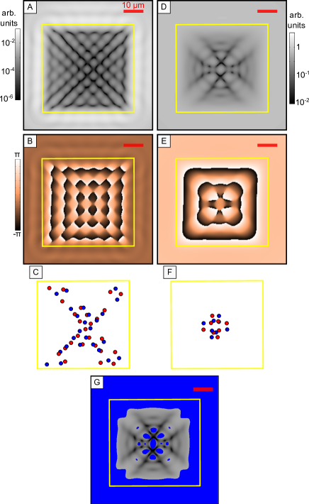
To better understand the vortex distribution, we study the correlations between the disappearance of the array of V-AV pairs and the subsonic character of the fluid. Since the distribution of the polariton fluid is not homogeneous, one has to define a local speed of sound where , and are the local polariton density, the coupling constant and the polariton mass. In the local density approximation wouters_spatial_2008 , corresponds to the speed of sound defined in the case of high densities (i.e. when the polariton density lies on the upper branch of the bistability curve and the Bogoliubov dispersion of the collective excitations is linear ciuti_quantum_2005 ) and therefore hereinafter we will simply call it generalized speed of sound. To study the existence of these correlations we evaluate the Mach number () defined as the ratio between the speed of the fluid (locally evaluated as the derivative of the phase at the point , and the generalized speed of sound ():
| (1) |
Figure 5G shows the Mach-number chart corresponding to the case of fig. 5D-F: in the region inside the trap but close to the borders, where V-AV pairs have disappeared, the system is in a subsonic regime due to its high density. Since a subsonic fluid cannot sustain strong phase modulations landau_chapter_1986 , V-AV pairs merge in the regions where the fluid becomes locally subsonic. Note that the disappearance of the V-AV pairs can not be ascribed to a simple renormalization of the lower polariton branch since this mechanism would lead to an increase of the lattice characteristic length. This is not the case in our system since the periodicity related to this characteristic length is still visible in Figures 2D and 5D. In our case V-AV pairs disappear because the increase of the polariton density forces vortices to overlap with antivortices and therefore to annihilate. On the other hand, as polaritons move towards the centre of the trap, due to their finite lifetime, their density decreases and so does the sound velocity of the fluid so that the fluid becomes mainly supersonic (). In this inner region, V-AV pairs can survive and the array is only slightly deformed. Therefore, the finite lifetime of cavity-polaritons and their out-of-equilibrium character allow the observation of different behaviors, at the same time, in different regions of the system. The coexistence of the two behaviors is a peculiar feature typical of cavity polaritons systems distinguishing them from other equilibrium systems like nonlinear optics and atomic condensates.
IV Conclusions
We have investigated the vortex lattices formation in exciton polariton systems as a function of the polariton density. In the linear regime we have demonstrated the generation of a lattice of vortices in microcavity polariton systems whose size, shape and unit-cell size can be easily controlled and are solely determined by the geometry of the system. When the polariton density is increased, strong polariton-polariton non linear interactions dominate and substantially modify the previously observed array. Our results not only show that the repulsion between polaritons can modify the effect of plane-wave interference and determine the array pattern, but also that the interactions can destroy the topological excitations of opposite winding number by merging one excitation with the other. Our simulations show the correlation between the disappearance of vortex-antivortex pairs and the local onset of the superfluid regime. While our system has a zero total angular momentum and therefore cannot support any single free vortex, Abrikosov-like lattices could be observed by breaking this symmetry therefore opening the way to the observation of mutual vortex-vortex interactions.
Appendix A Sample description
In our experiment we use a high finesse () GaAs microcavity containing three InGa0.95As quantum wells. The top/bottom Bragg mirrors are formed by 20 and 24 pairs of alternating layers of GaAs and AlAs with an optical thickness of , nm being the wavelength of the confined cavity mode. The Rabi splitting is about 5.1 meV, and the photon lifetime ps. Since the exciton linewidth is of the order of or slightly lower than the photon linewidth (as considered in the theoretical model), we obtain a polariton lifetime of the order of 10-15 ps. This value is consistent with others time-resolved experiments sanvitto_all-optical_2011 . The Bragg mirrors of the cavity form a wedge of a few degrees to allow a fine tuning of the exciton-photon detuning. The microcavity is excited with a continuous-wave single-mode Ti:Sa laser quasi resonant with the lower polariton branch lying in the infrared domain around 837 nm.
Appendix B Phase extraction procedure
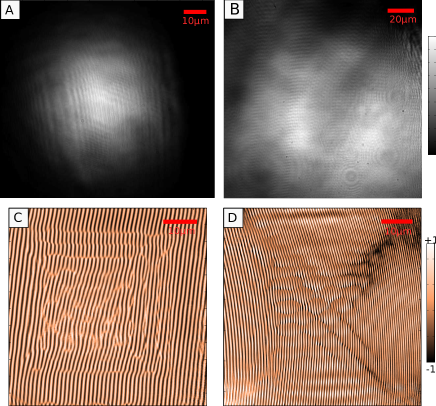
We detail here the phase extraction procedure. The signal coming from the microcavity (with amplitude and phase ) is sent into one arm of a Mach-Zehnder interferometer, while a reference beam (with amplitude and phase ) is sent into the other arm of the interferometer. The intensity of the reference beam (figure 6 panels A and B) is adjusted for each set of data in order to maximize the contrast of the interference pattern (), and the interference pattern is collected on a CCD camera (figure 6 panels C and D). The detected intensity is therefore proportional to where we assumed a perfect coherence between the two components and where is the phase modulation induced by the geometry of the interferometer (angle between arms and lenses). In order to extract the phase diagram we perform a numerical Fourier transform of the interferogram and isolate the off-axis component corresponding to the term . Then, we perform the inverse Fourier transform from which the phase (and the amplitude ) can be extracted by removing the geometrical term that can be measured separately.
Appendix C Theoretical Model
A standard way to model the dynamics of resonantly-driven polaritons in a planar microcavity is to use a Gross-Pitaevskii (GP) equation for coupled cavity and exciton fields ( and ) generalized to include the effects of the resonant pumping and decay ():
| (2) |
where the single particle polariton Hamiltonian is given by
| (3) |
and
| (4) |
is the cavity dispersion, with the photon mass and the bare electron mass. For the simulations we have assumed a flat exciton dispersion relation . The parameters , and are the Rabi frequency and the excitonic and photonic decay rates respectively and have been fixed to values close to experimental ones: meV, meV, and meV. In this model polaritons are injected into the cavity by a coherent and monochromatic laser field, with pump intensity and a Gaussian spatial profile with width of 50 m : . Here, in contrast to others cases fraser_2009 , we simulate the polariton system with a simplified two-fields model discarding the role of the excitonic reservoir since our setup is based on the use of a continuous-wave laser with a linewidth orders of magnitudes smaller than the Rabi splitting and therefore the injection of a reservoir of excitons is strongly suppressed. Part of the laser beam profile is set to zero in order to reproduce the effect of the gold-mask. To simulate the effect of not-perfectly reflecting edges of the mask, the pump intensity is set to decay exponentially from the border of the mask toward the centre. The exciton-exciton interaction strength is set to one by rescaling both the cavity and excitonic fields and the pump intensities. Our theoretical results come from the numerical solution of the GP equation over a two-dimensional grid (of points) in a box with sides of m2 using a fifth-order adaptive-step Runge-Kutta algorithm. All the analysed quantities are taken when the system has reached a steady state condition after a transient period of 200 ps.
Acknowledgements.
We would like to thank C. Tejedor for the use of the computational facilities of the Universidad Autonoma de Madrid, L. Martiradonna for the confocal mask, R. Houdré for the sample and Iacopo Carusotto for useful discussions. This work has been partially funded by the Quandyde project of the ANR France, by the POLATOM ESF Research Network Program and by the CLERMONT4 Network Progam. FMM acknowledges financial support from the programs Ramon y Cajal and Intelbiomat (ESF) and MHS from the EPSRC (grant EP/I028900/1). A. B. is member of Institut Universitaire de France (IUF).References
- (1) L. Onsager, “Statistical hydrodynamics,” Il Nuovo Cimento, vol. 6, pp. 279–287, Mar. 1949.
- (2) R. Feynman, “vol. 1 of progress in low temperature physics,” in vol. 1 of Progress in Low Temperature Physics, pp. 17–53, North-Holland, Amsterdam, 1955.
- (3) J. F. Nye and M. V. Berry, “Dislocations in wave trains,” Proceedings of the Royal Society of London. A. Mathematical and Physical Sciences, vol. 336, pp. 165–190, Jan. 1974.
- (4) A. S. Desyatnikov, Y. S. Kivshar, and L. Torner, “Optical vortices and vortex solitons,” in Progress in Optics (E. Wolf, ed.), vol. 47, pp. 291–391, Elsevier, Amsterdam, 2005.
- (5) U. Essmann and H. Träuble, “The direct observation of individual flux lines in type II superconductors,” Physics Letters A, vol. 24, pp. 526–527, May 1967.
- (6) E. J. Yarmchuk, M. J. V. Gordon, and R. E. Packard, “Observation of stationary vortex arrays in rotating superfluid helium,” Physical Review Letters, vol. 43, pp. 214–217, July 1979.
- (7) J. Scheuer and M. Orenstein, “Optical vortices crystals: Spontaneous generation in nonlinear semiconductor microcavities,” Science, vol. 285, pp. 230–233, Sept. 1999.
- (8) K. W. Madison, F. Chevy, W. Wohlleben, and J. Dalibard, “Vortex formation in a stirred bose-einstein condensate,” Physical Review Letters, vol. 84, pp. 806–809, Jan. 2000.
- (9) J. Denschlag, J. E. Simsarian, D. L. Feder, C. W. Clark, L. A. Collins, J. Cubizolles, L. Deng, E. W. Hagley, K. Helmerson, W. P. Reinhardt, S. L. Rolston, B. I. Schneider, and W. D. Phillips, “Generating solitons by phase engineering of a bose-einstein condensate,” Science, vol. 287, pp. 97–101, July 2000.
- (10) L. Khaykovich, F. Schreck, G. Ferrari, T. Bourdel, J. Cubizolles, L. D. Carr, Y. Castin, and C. Salomon, “Formation of a matter-wave bright soliton,” Science, vol. 296, pp. 1290–1293, May 2002.
- (11) A. Abrikosov, “On the magnetic properties of superconductors of the second group,” Soviet Physics Jetp-Ussr, vol. 5, no. 6, pp. 1174–1183, 1957. WOS:A1957WN04300022.
- (12) H. Deng, H. Haug, and Y. Yamamoto, “Exciton-polariton bose-einstein condensation,” Reviews of Modern Physics, vol. 82, pp. 1489–1537, May 2010.
- (13) I. Carusotto and C. Ciuti, “Quantum fluids of light,” Reviews of Modern Physics, vol. 85, pp. 299–366, Feb. 2013.
- (14) F. Dalfovo, S. Giorgini, L. P. Pitaevskii, and S. Stringari, “Theory of bose-einstein condensation in trapped gases,” Rev. Mod. Phys., vol. 71, no. 3, p. 463, 1999.
- (15) S. Burger, F. S. Cataliotti, C. Fort, F. Minardi, M. Inguscio, M. L. Chiofalo, and M. P. Tosi, “Superfluid and dissipative dynamics of a bose-einstein condensate in a periodic optical potential,” Physical Review Letters, vol. 86, pp. 4447–4450, May 2001.
- (16) J. Kasprzak, M. Richard, S. Kundermann, A. Baas, P. Jeambrun, J. M. J. Keeling, F. M. Marchetti, M. H. Szymanska, R. André, J. L. Staehli, V. Savona, P. B. Littlewood, B. Deveaud, and L. S. Dang, “Bose-Einstein condensation of exciton polaritons,” Nature, vol. 443, pp. 409–414, Sept. 2006.
- (17) I. Carusotto and C. Ciuti, “Probing microcavity polariton superfluidity through resonant rayleigh scattering,” Phys. Rev. Lett., vol. 93, no. 16, p. 166401, 2004.
- (18) M. Wouters and I. Carusotto, “Superfluidity and critical velocities in nonequilibrium bose-einstein condensates,” Phys. Rev. Lett., vol. 105, no. 2, p. 020602, 2010.
- (19) E. Cancellieri, F. M. Marchetti, M. H. Szymanska, and C. Tejedor, “Superflow of resonantly driven polaritons against a defect,” Phys. Rev. B, vol. 82, p. 224512, 2010.
- (20) E. Cancellieri, F. M. Marchetti, M. H. Szymanska, D. Sanvitto, and C. Tejedor, “Frictionless flow in a binary polariton superfluid,” Physical Review Letters, vol. 108, p. 065301, Feb. 2012.
- (21) A. Amo, D. Sanvitto, F. P. Laussy, D. Ballarini, E. d. Valle, M. D. Martin, A. Lemaitre, J. Bloch, D. N. Krizhanovskii, M. S. Skolnick, C. Tejedor, and L. Vina, “Collective fluid dynamics of a polariton condensate in a semiconductor microcavity,” Nature, vol. 457, pp. 291–295, Jan. 2009.
- (22) A. Amo, J. Lefrère, S. Pigeon, C. Adrados, C. Ciuti, I. Carusotto, R. Houdre, E. Giacobino, and A. Bramati, “Superfluidity of polaritons in semiconductor microcavities,” Nature Physics, vol. 5, no. 11, pp. 805–810, 2009.
- (23) D. Sanvitto, F. M. Marchetti, M. H. Szymanska, G. Tosi, M. Baudisch, F. P. Laussy, D. N. Krizhanovskii, M. S. Skolnick, L. Marrucci, A. Lemaitre, J. Bloch, C. Tejedor, and L. Vina, “Persistent currents and quantized vortices in a polariton superfluid,” Nature Physics, vol. 6, no. 7, pp. 527–533, 2010.
- (24) K. G. Lagoudakis, M. Wouters, M. Richard, A. Baas, I. Carusotto, R. André, L. S. Dang, and B. Deveaud-Plédran, “Quantized vortices in an exciton-polariton condensate,” Nature Physics, vol. 4, pp. 706–710, Sept. 2008.
- (25) K. G. Lagoudakis, T. Ostatnický, A. V. Kavokin, Y. G. Rubo, R. André, and B. Deveaud-Plédran, “Observation of half-quantum vortices in an exciton-polariton condensate,” Science, vol. 326, pp. 974–976, Nov. 2009. PMID: 19965506.
- (26) H. Flayac, I. A. Shelykh, D. D. Solnyshkov, and G. Malpuech, “Topological stability of the half-vortices in spinor exciton-polariton condensates,” Physical Review B, vol. 81, p. 045318, Jan. 2010.
- (27) G. Roumpos, M. D. Fraser, A. Löffler, S. Höfling, A. Forchel, and Y. Yamamoto, “Single vortex-antivortex pair in an exciton-polariton condensate,” Nature Physics, vol. 7, pp. 129–133, Feb. 2011.
- (28) G. Nardin, G. Grosso, Y. Léger, B. Piȩtka, F. Morier-Genoud, and B. Deveaud-Plédran, “Hydrodynamic nucleation of quantized vortex pairs in a polariton quantum fluid,” Nature Physics, vol. 7, pp. 635–641, Aug. 2011.
- (29) G. Tosi, F. M. Marchetti, D. Sanvitto, C. Anton, M. H. Szymanska, A. Berceanu, C. Tejedor, L. Marrucci, A. Lemaitre, J. Bloch, and L. Vina, “Onset and dynamics of vortex-antivortex pairs in polariton optical parametric oscillator superfluids,” Physical Review Letters, vol. 107, p. 036401, July 2011.
- (30) A. Amo, S. Pigeon, D. Sanvitto, V. G. Sala, R. Hivet, I. Carusotto, F. Pisanello, G. Leménager, R. Houdre, E. Giacobino, C. Ciuti, and A. Bramati, “Polariton superfluids reveal quantum hydrodynamic solitons,” Science, vol. 332, pp. 1167–1170, Mar. 2011.
- (31) R. Hivet, H. Flayac, D. D. Solnyshkov, D. Tanese, T. Boulier, D. Andreoli, E. Giacobino, J. Bloch, A. Bramati, G. Malpuech, and A. Amo, “Half-solitons in a polariton quantum fluid behave like magnetic monopoles,” Nature Physics, vol. 8, no. 10, pp. 724–728, 2012.
- (32) A. V. Gorbach, R. Hartley, and D. V. Skryabin, “Vortex lattices in coherently pumped polariton microcavities,” Physical Review Letters, vol. 104, p. 213903, May 2010.
- (33) J. Keeling and N. G. Berloff, “Spontaneous rotating vortex lattices in a pumped decaying condensate,” Physical Review Letters, vol. 100, p. 250401, June 2008.
- (34) T. C. H. Liew, Y. G. Rubo, and A. V. Kavokin, “Generation and dynamics of vortex lattices in coherent exciton-polariton fields,” Physical Review Letters, vol. 101, p. 187401, Oct. 2008.
- (35) K. Kusudo, N. Y. Kim, A. Loeffler, S. Hoefling, A. Forchel, and Y. Yamamoto, “Stochastic formation of polariton condensates in two degenerate orbital states,” arXiv:1211.3833, Nov. 2012.
- (36) F. Manni, T. C. H. Liew, K. G. Lagoudakis, C. Ouellet-Plamondon, R. André, V. Savona, and B. Deveaud, “Spontaneous self-ordered states of vortex-antivortex pairs in a polariton condensate,” Phys. Rev. B, vol. 88, p. 201303, Nov 2013.
- (37) S. Pigeon, I. Carusotto, and C. Ciuti, “Hydrodynamic nucleation of vortices and solitons in a resonantly excited polariton superfluid,” Physical Review B, vol. 83, p. 144513, Apr. 2011.
- (38) G. Tosi, G. Christmann, N. G. Berloff, P. Tsotsis, T. Gao, Z. Hatzopoulos, P. G. Savvidis, and J. J. Baumberg, “Geometrically locked vortex lattices in semiconductor quantum fluids,” Nature Communications, vol. 3, p. 1243, Dec. 2012.
- (39) P. Cristofolini, A. Dreismann, G. Christmann, G. Franchetti, N. G. Berloff, P. Tsotsis, Z. Hatzopoulos, P. G. Savvidis, and J. J. Baumberg, “Optical superfluid phase transitions and trapping of polariton condensates,” Physical Review Letters, vol. 110, p. 186403, May 2013.
- (40) R. Houdre, C. Weisbuch, R. P. Stanley, U. Oesterle, and M. Ilegems, “Coherence effects in light scattering of two-dimensional photonic disordered systems: Elastic scattering of cavity polaritons,” Phys. Rev. B, vol. 61, p. R13333, 2000.
- (41) C. Adrados, T. C. H. Liew, A. Amo, M. D. Martin, D. Sanvitto, C. Anton, E. Giacobino, A. Kavokin, A. Bramati, and L. Vina, “Motion of spin polariton bullets in semiconductor microcavities,” Physical Review Letters, vol. 107, p. 146402, Sept. 2011.
- (42) D. Sanvitto, S. Pigeon, A. Amo, D. Ballarini, M. D. Giorgi, I. Carusotto, R. Hivet, F. Pisanello, V. G. Sala, P. S. S. Guimaraes, R. Houdre, E. Giacobino, C. Ciuti, A. Bramati, and G. Gigli, “All-optical control of the quantum flow of a polariton condensate,” Nature Photonics, vol. 5, no. 10, pp. 610–614, 2011.
- (43) M. Vladimirova, S. Cronenberger, D. Scalbert, K. V. Kavokin, A. Miard, A. Lemaitre, J. Bloch, D. Solnyshkov, G. Malpuech, and A. V. Kavokin, “Polariton-polariton interaction constants in microcavities,” Physical Review B, vol. 82, p. 075301, Aug. 2010.
- (44) E. Wertz, L. Ferrier, D. D. Solnyshkov, P. Senellart, D. Bajoni, A. Miard, A. Lemaitre, G. Malpuech, and J. Bloch, “Spontaneous formation of a polariton condensate in a planar GaAs microcavity,” Appl. Phys. Lett., vol. 95, no. 5, p. 051108, 2009.
- (45) A. Baas, J. P. Karr, H. Eleuch, and E. Giacobino, “Optical bistability in semiconductor microcavities,” Physical Review A, vol. 69, p. 023809, Feb. 2004.
- (46) J. Masajada and B. Dubik, “Optical vortex generation by three plane wave interference,” Optics Communications, vol. 198, pp. 21–27, Oct. 2001.
- (47) M. Wouters, I. Carusotto, and C. Ciuti, “Spatial and spectral shape of inhomogeneous nonequilibrium exciton-polariton condensates,” Physical Review B, vol. 77, p. 115340, Mar. 2008.
- (48) C. Ciuti and I. Carusotto, “Quantum fluid effects and parametric instabilities in microcavities,” physica status solidi (b), vol. 242, no. 11, pp. 2224–2245, 2005.
- (49) L. D. Landau and E. M. Lifshitz, “chapter 6 : Superfluidity,” in Statistical Physics part 1 (2nd edition), Course of Theoretical Physics, Pergamon Press, Oxford, 1986.
- (50) M. D. Fraser, G. Roumpos, and Y. Yamamoto, “Vortex-antivortex pair dynamics in an exciton-polariton condensate,” New Journal of Physics, vol. 11, p. 113048, 2009.