Using a two-electron spin qubit to detect electrons flying above the Fermi sea
Abstract
We investigate experimentally the capacitive coupling between a two-electron spin qubit and flying electrons propagating in quantum Hall edge channels. We demonstrate that the qubit is an ultrasensitive and fast charge detector with the potential to allow single shot detection of a single flying electron. This work opens the route towards quantum electron optics at the single electron level above the Fermi sea.
pacs:
03.65.-w, 73.21.La, 73.22.fDuring the last two decades, an important effort has been devoted to the control of nanocircuits at the single electron level. It is now possible to isolate a single electron in a trap tarucha , to displace it deterministically hermelin ; mcneil ; thalineau and to manipulate it quantum mechanically koppens ; petta ; hayashi ; foletti ; brunner . An important requirement for these achievements is to have sensitive enough detectors to probe the presence of a single electron. Up to now, single electron detection is only possible while the electron is trapped within a quantum dot. For example, in an AlGaAs heterostructure two dimensional electron gas (2DEG), it is indeed possible to freeze for a sufficiently long time the electron in the quantum dot and detect it with a conventional on-chip electrometer field . For quantum experiments using flying electrons ji ; roulleau ; michi ; bocquillon ; glattli , this task is much more difficult: indeed the time of interaction between the detector and the flying electron usually does not exceed 1 ns and is fixed by the speed of the electron, the size of the on-chip electrometer and the width of the electronic wavepacket. This time is 2 orders of magnitude faster than the time needed to detect a single electron with the best on-chip charge detector demonstrated so far in a 2DEG barthel . This represents an important limitation for the investigation of quantum correlations in experiments with flying electrons.
To overcome this limitation, quantum systems have been identified as extremely sensitive systems to external perturbations and potentially good detectors gleyzes . They have been used for example to detect a single phonon excitation of a nanomechanical system oconnel . In a 2DEG, two quantum systems have been recently proposed to detect a propagating electron: a double quantum dot charge qubit and a Mach-Zender interferometer neder .
Here, we propose and demonstrate experimentally the potential of a two-electron spin qubit as an ultrasensitive charge detector by coupling it to individual electrons, propagating in the edge states of the Quantum Hall regime. The Singlet-Triplet () qubit in a double dot with two electrons is a quantum system where the two-electron antiparallel spin states can be manipulated on fast timescales by changing the energy detuning between the two dots. Moreover, the charge sensitivity of the qubit is tunable with and can be completely eliminated petta . In this charge insensitive configuration, the quantum information stored in the qubit can be preserved for a time longer than a few hundreds of microseconds bluhm . These properties allow interacting strongly for a very short time with a single electron, storing the resulting change in the population of the two-level system for a time sufficiently long and read-out the state of the qubit in a single shot with fast charge detection. In this way, single shot read out of flying electrons passing by the qubit could be performed.
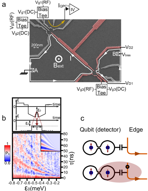
We study a sample made of two Ti-Au multigate systems defined on top of a AlGaAs-GaAs heterostructure 2DEG separated by a 3 long gate (see Fig. 1(a), details on the sample can be found in the Supplemental materials). By applying a perpendicular magnetic field of 0.73 T, the electronic system enters the quantum Hall regime with a filling factor and edge channels run along the gates. The gates on the upper part of the sample can be polarized with negative voltages in order to define the qubit (see Fig 1(b) and supplemental materials). The electric field generated by the single electron propagating in the edge state will slightly modify the electrostatic environment of the double dot (see Fig. 1(c)). It will therefore change the qubit energy splitting during the time of interaction and the frequency of the coherent oscillations between the antiparallel spin states. This results in a population change of the two-level system that can be stored for several tens of microseconds and then be measured by spin-to-charge conversion. In our experiment, we use two different ways to inject electrons into the edge state: either by a QPC or a fast tunable quantum dot (see Fig. 1(a) and supplemental materials).
The sensitivity of the detector to charge fluctuations can be evaluated from the -dependence of the coherent oscillations presented in Fig. 1(b). With a fit valid for meV, we obtain with neV, eV and eV. For a fixed detuning variation , the relative change in is independent of and equal to eV-1. Moreover the typical detector response timescale is set by the dynamics of the qubit. Therefore the more rapid the coherent oscillations are, the faster the detector responds. The most sensitive working point of the detector is then where the slope of the coherent exchange oscillations as a function of the interaction time is maximum. Knowing the shift detuning resulting from the coupling between a single flying electron and the detector permits evaluating the expected detector response for one electron.
To demonstrate experimentally the potential of such a detection method and evaluate the strength of , a flow of electrons is injected into the edge state closest to the gates in a controllable manner by a QPC (see supplemental materials). Within the Landauer-Büttiker formalism buttiker , the potential of the last edge state is fixed by the bias potential applied to the contact B. When is changed, we observe a variation of which results in faster (slower) oscillations when a negative (positive) bias is applied (see Fig. 2(a) and 2(b)). Indeed, the electric field induced by the closest edge state potential adds to the one generated by the gates and results in a change of . In this low-exchange-coupling regime, a eV shift in corresponds to a nA current flowing in the edge states (1 nA/eV), meaning that roughly an electron passes by every 0.2 ns. Such a detuning shift caused by the passage of a single electron corresponds to a change of the detector population of .
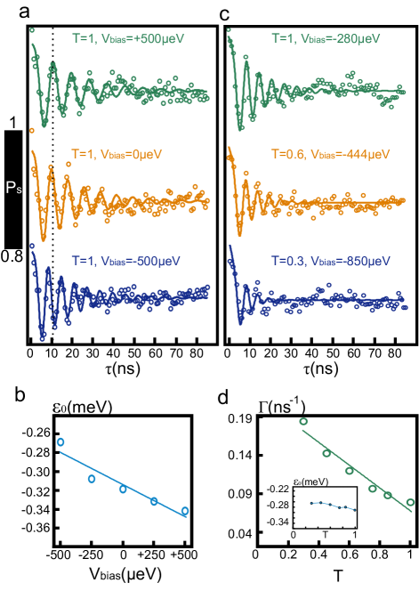
By changing the transparency of the injector QPC barrier, we observe that the detector is sensitive not only to the average current in the channel but also to the current shot noise and therefore to electron granularity. For this purpose, we vary both and such that the current in the edge state is kept constant (as shown in Fig. 2(c)). As expected, remains nearly unchanged as we change the working point (, ) (see inset Fig. 2(d)): the average number of electrons per second seen by the detector does not change. In addition, we observe a linear decrease of the decoherence rate (see Fig. 2(d)). In the case where the coupling between the detector and the electrons is small in comparison with the typical time scale of the detector, the Gaussian approximation is applicable and the Bloch-Redfield theory predicts that the decoherence rate is directly proportional to the spectral density of current noise ithier and equal to . In the situation of high bias relative to the probed frequency, the noise is expected to be frequency independent and the shot noise formula applies: . In keeping the current constant, is linear in as the observed linear dependence of decoherence rate with . The coupling extracted from the fit of the decoherence rate (see Fig. 2(d)) is an order of magnitude bigger than the one extracted by the exponentional fit of (see Fig. 1(c)) and the calibrated . Nevertheless, the data presented in Fig. 2(b) are taken at a position closer to the crossing between the (1,1) and (0,2) charge states and deviations from the exponential fit of the exchange coupling have been observed and result in higher sensitivity of the qubit to noise detuning dial . Therefore, the behaviour of the coherent oscillations is in good agreement with the current shot noise theory of a single transmitted channel through a QPC martin which allows us to assert that our detector is sensitive to individual flying electrons.
The time-response of the detector is set by the quantum dynamics of the qubit and therefore nanosecond time-resolved detection is possible. To demonstrate this experimentally, we need to excite the edge state and arm the qubit-detector at nanosecond timescales. For this purpose, we formed a quantum dot in the lower right part of the sample to inject an electron by triggering with a fast emission voltage pulse feve . The width of the electron wave packet is set by the tunnel barrier separating the quantum dot from the edge state and is estimated to be between 0.1-1 ns (see supplemental material). In this way, we change the edge potential at nanosecond timescales. To arm the detector only for a nanosecond, we only pulse the detuning for a nanosecond (see Fig. 3(a)). In this case, most of the evolution is happening when the pulse is close to its maximum value and therefore we estimate the relevant interaction time close to 0.5 ns. The resulting population evolution at fixed excitation time as a function of is presented in Fig. 3(b). As expected, we reproduce a part of the coherent evolution. From at meV and the coupling between the detector and a single flying electron, we extract the expected change in the detector population induced by the passage of a single electron to about .
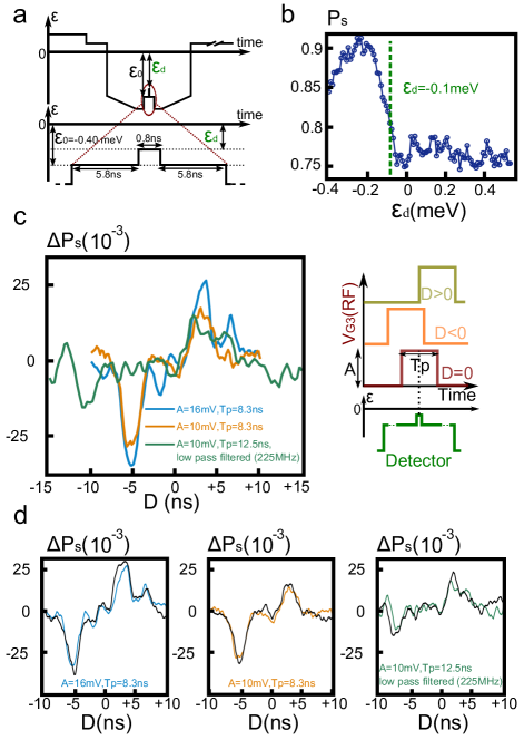
In Fig. 3(c), the evolution of the detector signal or the probability to detect the singlet state is plotted as a function of the delay between the emission and detection pulses with a step size of 0.2 ns. The two pulses are synchronized using the same arbitrary waveform generator. In this curve, one observes two large peaks, one positive for positive delay and one negative for negative delay. They correspond to the falling and rising edges of the emission pulse and are consistent with the emission of an electron and a lack of electron happening at this position (see Fig. 3(c)). Nevertheless, the amplitude of the peaks is larger than the estimated for a single flying electron. Moreover, when the emission pulse amplitude or rise time are reduced, this peak amplitude is diminishing. They are more likely the results of a local change in the electron density due to direct capacitive coupling between the pulsing gate called edge magneto-plasmons EMP ashoori . The excess or the lack of electrons is then provided by the coupling to the bulk at this low magnetic field regime. According to the extracted detector sensitivity, each pulse contains between 5 and 10 electrons.
The protocol described above is reproduced by pulsing the emitted quantum dot between two distinct charge state configurations or within a Coulomb blockade region. In this case, an electron or a lack of an electron is emitted in addition to the EMP only in the first case. Fig. 3(d) presents the comparison between the resulting detection curves. For each curve, one notices a small increase of the peak amplitude that we assign to the emitted electron or lack of an electron. It indeed corresponds to the amplitude expected from the detector-electron coupling. The signal is however small compared to the one induced by the EMP and a clear demonstration will only be possible by eliminating the EMP.
In conclusion, we capacitively coupled a qubit to electrons propagating in a quantum Hall edge state. When a stream of electrons is emitted with a QPC, we demonstrate that the qubit detector is not only sensitive to the average current but also to the current shot noise. In pulsed experiments where a fast tunable quantum dot is used as an emitter, we demonstrated that the two-electron spin qubit can be considered as a sufficiently fast detector with a high sensitivity that allows to detect few propagating electrons. Moreover, we observe that the single electron is accompanied by a cloud of EMP excited during the emission pulse. For future experiments, it would be important to minimize as much as possible these extra excitations.
In order to use such a detection method to detect quantum correlations in quantum optics experiments with flying electrons ji ; roulleau ; bocquillon , one needs first to use lower density samples in order to work at lower filling factor and below 1 T where the qubit is working. Second, the single shot regime of detection needs to be achieved. This last requirement is within experimental reach. Indeed, the gate geometry could be optimized to increase the coupling between the edge channel and the qubit and, more importantly, more complex qubit operations and faster detection schemes could be used in order to increase the fidelity of the qubit operation as demonstrated in shulman .
We acknowledge technical support from the ”Poles” of the Institut Néel as well as Pierre Perrier. We acknowledge the help of S. Hermelin in the device fabrication. Devices were fabricated at ”Plateforme Technologique Amont” of Grenoble, with the financial support of the ”Nanosciences aux limites de la Nanoélectronique” Foundation and CNRS Renatech network. A.D.W. acknowledges expert help from PD Dr. Dirk Reuter and support of the DFG SPP1285 and the BMBF QuaHLRep 01BQ1035. R. T. and T.M. acknowledges financial support from ERC ”QSPINMOTION”.
References
- (1) S. Tarucha et al., Phys. Rev. Lett. 77, 3613 (1996).
- (2) S. Hermelin et al., Nature 477, 7365 (2011).
- (3) R. P. Mc Neil et al., Nature 477, 7368 (2011).
- (4) R. Thalineau et al., Applied Physics Letter 101, 103102 (2012).
- (5) F. H. L. Koppens et al., Nature 442, 766 (2006).
- (6) J.R. Petta et al., Science 309, 2180 (2005).
- (7) T. Hayashi et al., Phys. Rev. Lett. 91, 226804 (2003).
- (8) S. Foletti et al., Nature Phys. 5, 903 (2009).
- (9) R. Brunner et al., Phys. Rev. Lett. 107, 146801 (2011).
- (10) M. Field et al., Phys. Rev. Lett. 70, 1311–1314 (1993).
- (11) Y. Ji et al., Nature 422, 415 (2003).
- (12) P. Roulleau et al., Phys. Rev. Lett. 100, 126802 (2008).
- (13) M. Yamamoto et al., Nature Nano. 7, 247 (2012).
- (14) E. Bocquillon et al., Science 339, 1054 (2013).
- (15) J. Dubois et al., Nature 502, 659 (2013).
- (16) C. Barthel et al., Phys. Rev. Lett. 103, 160503 (2009).
- (17) S. Gleyzes et al., Nature 446, 297 (2007).
- (18) D. O’Connell et al., Nature 464, 697 (2010).
- (19) I. Neder and F. Marquardt, New Journal of Physics 9,112 (2007).
- (20) H. Bluhm et al., Nature Phys. 7, 109-113 (2010).
- (21) M. D. Shulman et al., Science 336, 202 (2012).
- (22) R. Landauer, IBM Journal of Research and Development 1, 223 (1957), M. Büttiker, Phys. Rev. Lett. 57, 1761 (1986).
- (23) G. Ithier et al., Phys. Rev. B 72, 134519 (2005).
- (24) O. Dial et al., Phys. Rev. Lett. 110, 146804 (2013).
- (25) T. Martin and R. Landauer, Phys. Rev. B 45, 1742 (1992).
- (26) G. Feve et al., Science 316, 1169 (2007).
- (27) R. C. Ashoori et al., Phys. Rev. B 45(7), 3894 (1992).