An Institutional Framework for Heterogeneous
Formal Development in UML
Abstract
We present a framework for formal software development with UML. In contrast to previous approaches that equip UML with a formal semantics, we follow an institution based heterogeneous approach. This can express suitable formal semantics of the different UML diagram types directly, without the need to map everything to one specific formalism (let it be first-order logic or graph grammars). We show how different aspects of the formal development process can be coherently formalised, ranging from requirements over design and Hoare-style conditions on code to the implementation itself. The framework can be used to verify consistency of different UML diagrams both horizontally (e.g., consistency among various requirements) as well as vertically (e.g., correctness of design or implementation w.r.t. the requirements).
1 Introduction
Historically, industrial standards on software quality merely mentioned formal methods for the sake of completeness. Nowadays, each new (edition of a) standard brings formal methods more to the fore. Thanks to this trend, current standards elaborate on formal methods and often recommend their use as an important means to establish a design’s correctness and robustness. Recent examples include the 2011 version of the CENELEC standard on Railway applications, the 2011 ISO 26262 automotive standard, or the 2012 Formal Methods Supplement to the DO-178C standard for airborne systems.
In industrial software design, the Unified Modeling Language (UML) is the predominately used development mechanism. In aerospace industry, e.g., the company AEC uses the UML to define the software architecture of aeroplane engine controllers through various levels of abstraction from a layered architecture overview to a detailed class, operation and attribute definition of the software components. This model is then used for code generation. Typically, the software components developed are either reactive in nature or the components are logic-based and/or stateful in nature, where notations such as UML state diagrams are used to define the required behaviour. Similarly, the UML is used in micro-controller development in the automotive sector. An example out of the medical sector is the development of ventricular assist devices, to name just a few uses of UML for the development of critical systems.
The UML is an OMG standard [20], which describes a family of languages. It offers 14 types of diagrams of both structural and behavioural nature. A typical development by AEC easily involves eight different UML diagrams. The OMG specification provides an informal semantics of nine sub-languages in isolation. The languages are mostly linked through a common meta-model, i.e., through abstract syntax only. This situation leads to a gap between standards’ recommendation to apply formal methods, and current industrial practice, which by using the UML lacks the semantic foundations to apply such methods. One common approach to deal with this gap is to define a comprehensive semantics for the UML using a system model, e.g., [2, 3]. However, such an approach is a thorny business, as every detail has to be encoded into one, necessarily quite complex semantics. Furthermore, UML’s widespread adoption in industry is primarily due to its versatility; it lends itself to variations of usage, and different subsets of the UML tend to be used in different ways by different companies, leading to company or domain-specific variations.
In this paper, we outline a competing approach by providing a heterogeneous semantics. In this approach, we express the meaning of a model in a sub-language/diagram directly in an appropriate semantic domain and look for connections given by the abstract syntax of the UML specification or which can be gleaned from its semantic description. This separation between the meaning of the individual diagrams and how they are related allows our approach to adopt to different methodologies, for instance an object-oriented approach or a component-based one.
2 Methodology
Our overall aim is to providing Qualified Formal Methods for dependable software design for critical systems, especially embedded, reactive systems. This will cover requirements, design, code and deployment.
2.1 ATM case study
In order to illustrate our heterogeneous semantics, we present as a running example the design of a traditional automatic teller machine (ATM) connected to a bank. For simplicity, we only describe the handling of entering a card and a PIN with the ATM. After entering the card, one has three trials for entering the correct PIN (which is checked by the bank). After three unsuccessful trials the card is kept.
Requirements.
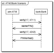
Figure 1 shows a possible interaction between an atm and a bank object, which consists out of four messages: the atm requests the bank to verify if a card and PIN number combination is valid, in the first case the bank requests to reenter the PIN, in the second case the verification is successful.
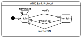
This interaction presumes that the system has atm and a bank objects. This can, e.g., be ensured by a composite structure diagram, see Fig. 5, which — among other things — specifies the objects in the initial system state. In order to communicate with a bank object, we assume the atm object to have a behaviour port called bankCom. This port’s dynamic behaviour is captured with a protocol state machine, see Fig. 2.
Design.
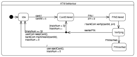
The dynamic behaviour of the atm object is specified by the state machine shown in Fig. 3. The machine consists of five states including Idle, CardEntered, etc. Beginning in the initial Idle state, the user can trigger a state change by entering the card. This has the effect that the parameter c from the card event is assigned to the cardId in the atm object (parameter names are not shown in a state machine diagram). Entering a PIN triggers another transition to PINEntered. Then the ATM requests verification from the bank using its bankCom port. The transition to Verifying uses a completion event: No explicit trigger is declared and the machine autonomously creates such an event whenever a state is completed, i.e., all internal activities of the state are finished (in our example there are no such activities). In case the interaction with the bank results in reenterPIN, and the guard trialsNum < 3 is true, the user can again enter a PIN.
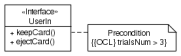
Figure 4 provides structural information in form of an interface diagram for the userCom port of the atm object. An interface is a set of operations that other model elements have to implement. In our case, the interface takes the form of a class diagram. Here, the operation keepCard is enriched with the OCL constraint trialsNum > 3, which refines its semantics: keepCard can only be invoked if the OCL constraints holds.
Code.
The state machine shown in Fig. 3 can be implemented in the programming language C, enriched with pre-/post-conditions written in the ANSI/ISO C Specification Language (ACSL). The below code example shows how the event card is encoded as C function, where the ACSL annotations ensure that the system is in some defined state and that the number of trials to re-enter the PIN is smaller than three.
Deployment.
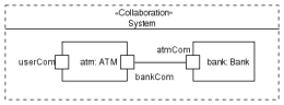
Finally, the composite structure diagram in Fig. 5 shows the initial state of our ATM system, in which an atm object and a bank object collaborate, where the atm has a bankCom port, whilst the bank has an atmCom port.
2.2 From Requirements to Design to Code
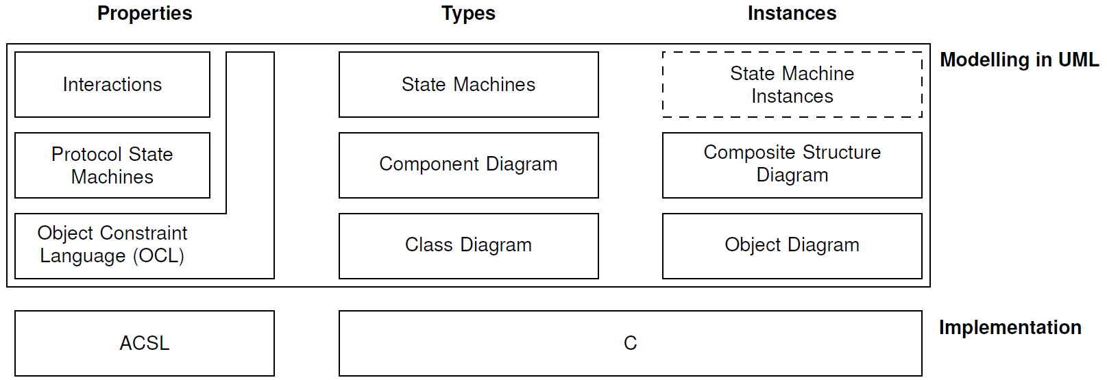
The languages and UML diagram types that we consider are shown in Fig. 6. On the modelling level we use parts of the UML and the Object Constraint Language (OCL). On the implementation level we currently employ the programming language C and ACSL. It is left for future work to also include a proper object-oriented language such as Java together with some specification formalism. In the types view of the modelling level we look at class diagrams for modelling data; component diagrams for modelling components; and state machines for specifying dynamic behaviour. These diagrams can be instantiated in the instance view using composite structure diagrams for showing component configurations; and object diagrams for showing concrete data. Although they are not present in UML 2, we also have added state machine instances (in a dashed box). Requirements on the models can be specified in the properties view using interactions, i.e., sequence diagrams or communication diagrams, for prescribing message exchanges between components and objects; protocol state machines for specifying port behaviour; and the Object Constraint Language for detailing the behaviour of components and objects in terms of invariants and method pre-/post-conditions.
2.3 Consistency and Satisfiability
During a model-driven development, it is desirable to detect inconsistencies at an early stage in order to ease corrections and avoid costly re-engineering at a late stage (e.g. during the implementation phase). While there are some tools providing static inconsistency checks based on UML’s meta-model, only few works consider dynamic checks, and generally only for specific UML diagram types, e.g. [14].
We will now outline a systematic method for the analysis of UML models and their interrelation to code. The analysis of UML models can proceed either horizontally within the requirements or within the design level checking for consistency within the level, or vertically checking for satisfaction between these two levels. A typical horizontal consistency check on the requirements level would ask if the sequential composition of actions in an interaction diagram is justified by an accompanying OCL specification. A typical vertical satisfiability check between the requirements and the design level would ask if the behaviour prescribed in an interaction diagram is realisable by several state machines cooperating according to a composite structure diagram. Code generation transforms a UML logical design to code templates with semantic annotations in the form of pre/post conditions and invariants. If the templates are completed satisfying the semantic annotations, it is guaranteed that the resulting code is a correct model of the logical design and therefore, by the vertical checks, also for the requirements.
3 UML as a Heterogeneous Formal Method, Using Institutions
In this section, we will provide semantic foundations for model based specification and design using a heterogeneous framework based on Goguen’s and Burstall’s theory of institutions [11]. We handle the complexity of giving a coherent semantics to UML by providing several institutions formalising different diagrams of UML, and several institution translations (formalised as so-called institution morphisms and comorphisms) describing their interaction and information flow. The central advantage of this approach over previous approaches to formal semantics for UML (e.g. [14]) is that each UML diagram type can stay “as-is”, without the need of a coding using graph grammars (as in [9]) or some logic (as in [14]). This also keeps full flexibility in the choice of verification mechanisms. The formalisation of UML diagrams as institutions has the additional benefit that a notion of refinement comes for free, see [19, 6].
This systematic coverage in a single semantic based Meta-formalism is unique. We provide semantic links in the form of institution (co-)morphisms, that, on the one hand, provide the basis for correct model transformations and validations, and on the other hand give rise to an integrated semantic view (via the so-called Grothendieck institution [7, 15]) on the identified UML subset as well as the target implementation languages. Institution theory provides an adequate abstraction level for such a semantic integration. The framework is flexible enough to support various development paradigms as well as different resolutions of UML’s semantic variation points. This is the crucial advantage of the proposed approach to the semantics of UML, compared to existing approaches in the literature which map UML to a specific global semantic domain in a fixed way.
3.1 Heterogeneous Formal Semantics of Languages and Diagrams
To carry out this program of institutionalising UML in all detail goes beyond scope and space limits of this paper. We only present some cornerstones and sketch how this can be extended to all diagrams in Fig. 6.
For substantial fragments of several UML diagram types, we have already provided a formalisation as institutions:
- Class diagrams
- Component diagrams
-
form an institution similar to that for class diagrams. The main difference are the connector types, which however are quite similar to associations.
- Object diagrams
-
are essentially reifications of models of class diagrams.
- Composite structure diagrams
-
are similar to object diagrams. The main difference are the connectors, which however are quite similar to the links of object diagrams.
- Interactions
-
in [5], we have sketched an institution for interactions, as well as their interconnection (also with class diagrams) via institution comorphisms.
- OCL
Thus, the central remaining challenge for institutionalisting UML are state machines and protocol state machines. Below, we sketch institutions for these, which are very similar. Only their sentences differ in that protocol state machines have a post condition instead of an action. Post conditions can also speak about messages being sent (using OCL). Formalising both C and ACSL as institutions is future work.
3.2 Institutions and Their (Co)Morphisms
Institutions are an abstract formalisation of the notion of logical system. Informally, institutions provide four different logical notions: sigantures, sentences, models and satisfaction. Signatures provide the vocabulary that may appear in sentences and that is interpreted in models. The satisfaction relation determines whether a given sentence is satisfied in a given model. The exact nature of signatures, sentences and models is left unspecified, which leads to a great flexibility. This is crucial for the possibility to model UML diagrams (which in the first place are not “logics”) as institutions.
An important feature of institutions is the presence of signature morphisms, which cna be seen as mappings between signatures. Sentences can be translated along signature morphisms, and models reduced against signature morphisms. The satisfaction condition states that satisfaction is invariant under change of notation (along a signature morphism).
We briefly recall the formal definition of institutions from [11]. An institution consists of (i) a category of signatures ; (ii) a sentence functor , where is the category of sets; (iii) a contra-variant model functor , where is the category of classes; and (iv) a family of satisfaction relations indexed over , such that the following satisfaction condition holds for every signature morphism in , every sentence and for every -model :
is called the reduct functor (also written ), the translation function (also written ).
It is possible to define standard logical notions like logical consequence, logical theory, satisfiabilty etc. as well as languages for structured specification and refinement in an institution-independent way [21].
For relating institutions in a semantics preserving way, we consider institution morphisms. Given institutions and , an institution morphism consists of (i) a functor ; (ii) a natural transformation ; and (iii) a natural transformation , such that the following satisfaction condition is satisfied for all , , and :
Dually, we consider institution comorphisms. Given institutions and , a simple institution comorphism consists of (i) a functor ; (ii) a natural transformation ; and (iii) a natural transformation , such that the following satisfaction condition is satisfied for all , , and :
The methodological need for these two kinds of mappings between institutions will be explained in Sect. 3.4 below.
3.3 Towards an Institution for UML State Machines
We will now formalise a simplified version of UML state machines as institutions. In particular, we omit hierarchical states. We start with an institution for the environment of a state machine. This environment fixes the conditions which can be used in guards of transitions, the actions for the effects of transitions, and also the messages that can be sent from a state machine. The source of this information typically is a class or a component diagram: The conditions and actions involve the properties available in the classes or components, the messages are derived from the available signals and operations. The sentences of this environment institution form a simple dynamic logic (inspired by OCL) which can express that if a guard holds as pre-condition, when executing an action, a certain set of messages has been sent out, and another guards holds as post-condition. We then build a family of institutions for state machines over this environment institution, which is parameterised in the environment. A state machine adds the events and states that are used. The events comprise the signals and operations that can be accepted by the machine; some of these will, in general, coincide with the messages from the environment. Additionally, the machine may react to completion events, i.e., internal events that are generated when a state of the machine has been entered and which trigger those transitions that do not show an explicit event as their trigger in the diagrammatic representation (we use the states as the names of these events). The initial state as well as the transitions of the machine are represented as sentences in the institution. In a next step, we combine the family of state machine institutions parameterised over the environments into a single institution. Finally, we present a product construction on the combined institution that captures communicating state machines from a composite structure diagram.
Environment institution.
An object of the category of environment signatures is a triple of sets
of guards, actions, and messages; and a morphism of is a triple of functions . The class of environment structures for an environment signature consists of the triples
where is a set of data states, expresses that the state satisfies guard , and that action leads from state to state producing the set of messages . The reduct of an -environment structure along the morphism is given by where and if, and only if . The set of environment sentences for an environment signature comprises the expressions
with , , and , intuitively meaning (like an OCL constraint) that if the pre-condition currently holds, then, after executing , the messages are produced and the post-condition holds. The translation of a sentence along the signature morphism is given by . Finally, the satisfaction relation holds if, and only if, for all , if and , then and . Then the satisfaction condition is shown easily.
Example 1.
Consider the UML component ATM with its properties cardId, pin, and trialsNum, its ports userCom and bankCom, and its outgoing operations ejectCard() and keepCard() to userCom, and verify() and markInvalid() to bankCom. An environment signature for ATM is derived by forming guards, actions, and messages over this information, such that it will contain the guards true and trialsNum == 0, the actions user.ejectCard(); trialsNum = 0 and trialsNum++, as well as the messages user.ejectCard() and bank.markInvalid(cardId). Environment sentence over such an environment signature could be (for )
State machine institution.
The institution of state machines is now built over the environment institution. Let be an environment signature and an environment structure over . An object of the category of state machine signatures over and is given by the pairs
of events and states with ; and a morphism of is a pair of injective functions . The class of state machine structures for a state machine signature over and consists of the pairs
where represents the initial configurations, fixing the initial control state; and with represents a transition relation from a configuration, consisting of an environment state, an event pool, and a control state, to a configuration, emitting a set of messages. The event pool may contain both events declared in the signature (from signals and operations) and completion events (represented by states). The reduct of a state machine structure along the morphism is given by the structure where and if and if . The set of state machine sentences for a state machine signature over and consists of the pairs
where means an initial state and represents the transitions from a state with a triggering event (either a declared event or a completion event), a guard, and an action to another state. The translation of a sentence along the signature morphism is given by . Finally, the satisfaction relation holds if, and only if and
where expresses that is the next event to be processed by the machine according to some selection scheme from the pool (where completion events are prioritized), and adds the events in to the pool . The messages on a transition in the structure are only thosed that are not accepted by the machine itself, i.e., not in . The accepted events in as well as the completion event when entering state are added to the event pool of the target configuration. When no transition is triggered by the current event, the event is discarded (this will happen, in particular, to all superfluously generated completion events). With these definitions, checking the satisfaction condition
for a state machine signature morphism is straightforward.
Example 2.
Consider the state machine of Fig. 3 defining the behaviour of ATM. It works over the environment signature sketched in the previous example, and its signature is with
The state machine can be represented as the following sentence over this signature:
In particular, PINEntered occurs both as a state and as a completion event in the third transition. The junction pseudostate for making the decision whether trialsNum < 2 or trialsNum >= 2 has been resolved by combining the transitions.
Protocol state machine institution.
Protocol state machines differ from behavioural state machines by not mandating a specific behaviour but just monitoring behaviour: They do not show guards and effects, but a pre- and a postcondition for the trigger of a transition. Moreover, protocol state machines do not just discard an event that currently does not fire a transition; it is an error when such an event occurs.
For adapting the state machine institution to protocol state machines we thus change the sentences to
where the two occurrences of represent the pre- and the post-conditions, and represents the messages that have to be sent out in executing the triggering event (protocol state machines typically do not show completion events). The satisfaction relation now requires that when an event is chosen from the event pool the pre-condition of some transition holds in the source configuration, its post-condition holds in the target configuration, and that all messages have been sent out. Instead of the second clause of , discarding an event, a dedicated error state is targeted when no transition is enabled. color=gray,size=]We could claim that there is a co-morphism from the protocol state machine to the environment institution and/or the OCL institution — but this seems to be quite bold.
Flat state machine institution.
We now flatten the institutions for each environment signature and each environment structure over into a single institution 111This is an instance of a general construction, namely the Grothendieck institution [7].222The sharing of guards and actions could also be covered by a push-out construction.