Radiation Emission by Electrons Channeling in Bent Silicon Crystals
Abstract
Results of numerical simulations of electron channeling and emission spectra are reported for straight and uniformly bent silicon crystal. The projectile trajectories are computed using the newly developed module NewPaper_2013 of the MBN Explorer package MBN_ExplorerPaper ; MBN_ExplorerSite . The electron channeling along Si(110) crystallographic planes is studied for the projectile energy 855 MeV.
1 Introduction
The basic effect of the channeling process in a straight crystal is in an anomalously large distance which a charged projectile can penetrate moving along a crystallographic plane (the planar channeling) or an axis (the axial channeling) experiencing collective action of the electrostatic field of the lattice ions Lindhard . The field is repulsive for positively charged projectiles so that they are steered into the inter-atomic region. Negatively charged particles, electrons in particular, move in the close vicinity of ion strings.
The channeling can also occur in a bent crystal provided the bending radius is large enough in comparison with the critical one Tsyganov1976 .
Channeling of a charged particle is accompanied by the channeling radiation ChRad:Kumakhov1976 which is due to channeling oscillations of the particle under the action of an interplanar or an axial field. The radiation intensity depends on the type of the projectile and on its energy as well as on the type of a crystal and a crystallographic plane (axis). The phenomenon of channeling radiation of a charged projectile in a straight crystal is well known (see, for example, Refs. Instrum ; Andersen_ChanRadReview_1983 ; BakEtal1985 ; BakEtal1988 ; BazylevZhevago ; RelCha ; Kumakhov2 ; SaenzUberall1981 ; Uggerhoj1993 ; Uggerhoj_RPM2005 ; Uggerhoj2011 ). Various aspects of radiation formed in crystals bent with the constant curvature radius were discussed in Refs. ArutyunovEtAl_NP_1991 ; Bent_Rad:Arutyunov1 ; Bashmakov1981 ; KaplinVorobev1978 ; SolovyovSchaeferGreiner1996 ; Taratin_Review_1998 ; TaratinVorobiev1988 ; TaratinVorobiev1989 although with various degree of detail.
The motion of a channeling particle in a bent crystal contains two components: the channeling motion and the translation along the centerline of the bent channel. The latter motion gives rise to the synchrotron-type radiation Landau2 ; Jackson . Therefore, the total spectrum of radiation formed by an ultra-relativistic projectile in a bent crystal contains the features of channeling radiation and those of synchrotron radiation. The condition of stable channeling in a bent crystal, , Tsyganov1976 ; BiryukovChesnokovKotovBook implies that the bending radius exceeds greatly the (typical) curvature radius of the channeling oscillations. Therefore, the synchrotron radiation modifies mainly the soft-photon part of the emission spectrum. Study of this part of the spectrum is especially important in connection with the concept of a crystalline undulator KSG1998 ; KSG_review_1999 . By means of crystalline undulator it is feasible to produce monochromatic undulator-like radiation in the hundreds of keV up to the MeV photon energy range. The intensity and characteristic frequencies of the radiation can be varied by changing the type of channeling particles, the beam energy, the crystal type and the parameters of periodic bending (see recent review ChannelingBook2013 for more details).
In recent years, several experiments were carried out to measure the channeling parameters and the characteristics of emitted radiation of sub-GeV light projectiles. These include the attempts made BaranovEtAl_CU_2006 or planned to be made Backe_EtAl_2011a ; Backe_EtAl_2008 to detect the radiation from a positron-based crystalline undulator. More recently, a series of the experiments with straight, bent and periodically bent crystals have been carried out with 195–855 MeV electron beams at the Mainz Microtron (Germany) facility Backe_EtAl_2010 ; Backe_EtAl_2011 ; Backe_EtAl_2013 . The crystalline undulators, used in the experiment, were manufactured in Aarhus University (Denmark) using the molecular beam epitaxy technology to produce strained-layer Si1-xGex superlattices with varying germanium content MikkelsenUggerhoj2000 ; Darmstadt01 . Another set of experiments with diamond crystalline undulators is planned within the E-212 collaboration at the SLAC facility (USA) with 10…20 GeV electron beam SLAC_FACET .
Theoretical support of the ongoing and future experiments as well as accumulation of numerical data on channeling and radiative processes of ultra-relativistic projectiles in crystals of various content and structure must be based on an accurate procedure which allows one to simulate the trajectories corresponding to the channeling and non-channeling regimes. Recently, a universal code to simulate trajectories of various projectiles in an arbitrary scattering medium, either structured (straight, bent and periodically crystals, superlattices, nanotubes etc) or amorphous (solids, liquids) has been developed as a new module NewPaper_2013 of the MBN Explorer package MBN_ExplorerPaper ; MBN_ExplorerSite . To simulate propagation of particles through media the algorithms used in modern molecular dynamics codes were utilized. Verification of the code against available experimental data as well as against predictions of other theoretical models were carried out for electron and positron channeling in straight Si(110) as well as in amorphous Si NewPaper_2013 . In more recent papers BentSilicon_2013 ; Sub_GeV_2013 the simulations were extended to the case of bent and periodically bent Si(110) and Si(111) channels. In the cited papers, critical analysis was carried out of the underlying physical model and the algorithm implemented in the recent code for electron channeling described in Refs. KKSG_simulation_straight . It was shown, that the specific model for electron–atom scattering leads in a noticeable overestimation of the mean scattering angle and, as a result, to the underestimation of the dechanneling length.
In this paper we present new results on electron channeling and emission spectra in straight and uniformly bent silicon crystal. The electron channeling along Si(110) crystallographic planes are studied for the projectile energy = 855 MeV for two lengths of a crystalline sample and for different bending curvatures.
2 Electron Channeling in Si (110)
2.1 Simulation of the Channeling Process with MBN Explorer
To perform 3D simulation of the propagation of an ultra-relativistic projectile through a crystalline medium two additional features were added to the molecular dynamics algorithms used in the MBN Explorer package MBN_ExplorerPaper . The first feature concerns the implementation and integration of the relativistic equations of motion. The second one is the dynamic generation of the crystalline medium. In detail, these features are described in NewPaper_2013 . Below in this section we outline the key points only.
Within the framework of classical mechanics the motion of an ultra-relativistic projectile of the charge and mass in an external electrostatic field is described by the equations:
| (1) |
Here is momentum, is the Lorenz factor, is the projectile energy and is the speed of light. Equations (1) are to be integrated for using the initial values of the coordinates and velocity of the particle at the crystal entrance.
To describe the motion in a scattering medium (a crystal, in particular) it is important to compute accurately and efficiently the electrostatic field due to the medium atoms. In the channeling module of MBN Explorer the field is calculated as , where electrostatic potential is a sum of atomic potentials
| (2) |
where stands for the position vector of the -th atom. The atomic potentials are evaluated within the Molière approximation, see, e.g., Baier .
Formally, the sum in Eq. (2) is carried out over all atoms of the crystal. However, accounting for a rapid decrease of at the distances from the nucleus (here the Thomas-Fermi radius is chosen to estimate the mean atomic radius), one can introduce the cutoff above which the contribution of is negligible. Therefore, for a given observation point the sum can be restricted to the atoms located inside a sphere of the radius . To facilitate the search for such atoms the linked cell algorithm is employed. As a result, the total number of computational operations is reduced considerably.
To simulate the channeling motion along a particular crystallographic plane with Miller indices the following algorithm is used NewPaper_2013 .111Axial channeling can also be simulated. For the sake of clarity, here we refer to the case of planar channeling.
As a first step, a crystalline lattice is generated inside the simulation box of the size . The -axis is oriented along the beam direction and is parallel to the plane, the axis is perpendicular to the plane. To avoid the axial channeling (when not desired) the -axis is chosen to be not collinear with major crystallographic axes. The position vectors of the nodes () within the simulation box are generated in accordance with the type of the Bravais cell of the crystal and using the pre-defined values of the the lattice vectors.
Once the nodes are defined, the position vectors of the atomic nuclei are generated with account for random displacement from the nodal positions due to thermal vibrations. The Cartesian components , , are normally distributed:
| (3) |
Here is the root-mean-square amplitude of thermal vibrations. Its values for various crystals at room temperature can be found in Gemmel .
Integration of equation (1) starts at when the particle “enters” the crystal at . The initial coordinates and are randomly chosen to be lying in the central part of the -plane of the sizes , where is the interplanar spacing of the planes. The initial velocity is predominantly oriented along , i.e. the conditions are implied. The transverse components can be chosen with account for the beam emittance.
To simulate the propagation of a particle through a crystal of finite thickness a new type of boundary conditions, the “dynamic simulation box”, has been implemented in MBN Explorer NewPaper_2013 . This algorithm implies the following.
A projectile moves within the simulation box interacting with the atoms lying inside the cutoff sphere. Once the distance from the projectile to the nearest face becomes a new simulation box of the same size is generated with its geometrical center coinciding (approximately) with the position of the projectile. To avoid spurious change in the force , the positions of the atoms located in the intersection of the old and the new simulation boxes are not changed. In the rest part of the new box the positions of atomic nuclei are generated following the scheme described above.
The motion in the amorphous medium can also be simulated. For doing this it is necessary to avoid incidental alignment of the initial velocity with major crystallographic directions. This regime is useful to calculate the spectral and spectral-angular distribution of the incoherent bremsstrahlung.
To simulate a bent crystal, the coordinates of each lattice node are obtained from the coordinates of the same node in the straight crystal according to the relations , , , where
| (4) |
is the shape of the bent crystallographic plane with bending radius . The approximate equation is valid if .
In a bent crystal, the channeling condition Tsyganov1976 implies that the centrifugal force is smaller than the maximum interplanar force . Thus, the value of the bending parameter
| (5) |
must be much less than one. The case characterizes to the straight crystal. The value corresponds to the critical (minimum) radius at which the potential barrier between the channels disappear. The value can been estimated withing the continuous approximation for the planar potential. For Si(110) one can use GeV/cm at room temperature BiryukovChesnokovKotovBook .
2.2 Numerical Results for MeV Electron Channeling in Si(110)
MBN Explorer was used to simulate the trajectories 855 Mev electrons in straight and bent silicon crystals incident at along the (110) crystallographic planes. The calculations were performed for two values of the crystal length, 25 and 75 m, measured along the beam direction.
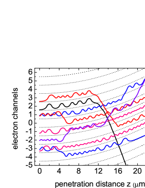
Several selected trajectories, which refer to the crystal bent with radius cm, are presented in Fig. 1. They illustrate a variety of features which characterize the electron motion: the channeling mode, the dechanneling, the over-barrier motion, the rechanneling process, rare events of hard collisions etc. First, let us note that since the dechanneling length of a 855 MeV electron in straight Si(110) is m NewPaper_2013 ; BentSilicon_2013 , it is not surprising that the events of channeling through the whole crystal are quite rare. For the indicated value of the bending radius only % of the incident particles travel through 25 m thick crystal moving in the channeling mode in the same channel where they were captured at the entrance. On the other hand, the events of rechanneling, i.e., capture to the channeling mode of an over-barrier particle, are quite common for electrons KKSG_simulation_straight ; NewPaper_2013 ; BentSilicon_2013 . Even the multiple rechanneling events are not rare. The rechanneling process, as well as the dechanneling one, is due to the random scattering of a projectile from the crystal constituents. In each scattering event the projectile can either increase or decrease its transverse energy . The sequence of the events with can lead to the dechanneling of initially channeled particle. The opposite process, resulting in a noticeable reduction of of the over-barrier particle, can also occur leading to the capture of the particle into the channeling mode, i.e., the rechanneling.
The simulated trajectories were used to estimate the dechanneling length (in the case of the electron channeling) and to calculate spectral distribution of the emitted radiation.
| (cm) | (m) | (m) | (m) | |||
|---|---|---|---|---|---|---|
| 0.0 | 0.66 | 12600 | ||||
| 70 | 0.002 | 0.65 | 11950 | |||
| 25 | 0.006 | 0.64 | 11950 | |||
| 13 | 0.01 | 0.65 | 12000 | |||
| 7 | 0.02 | 0.64 | 12000 | |||
| 2.5 | 0.06 | 0.55 | 12000 | |||
| 1.3 | 0.1 | 0.44 | 12050 | |||
| 0.75 | 0.2 | 0.34 | 4300 | |||
| 0.45 | 0.3 | 0.22 | 4500 |
Although the particles are initially directed along the (110) planes, not all of them become captured into the channeling mode at the crystal entrance. The important parameter to estimate is the acceptance, which is defined as a ratio of the number of particles captures into the channeling mode at the entrance (the accepted particles) to the total number of the simulated trajectories (the incident particles):
| (6) |
To quantify the dechanneling process of the accepted particles the following two penetration depths were introduced in Ref. NewPaper_2013 . The first one, notated below as , is found as a mean value of the primary channeling segments, which started at the entrance and lasted till the dechanneling point somewhere inside the crystal. Generally speaking, this quantity is dependent on the angular distribution of the particles at the entrance. The second penetration depth, , is defined as a mean value of all channeling segments, including those which are due to the rechanneling. In the rechanneling process an electron is captured into the channeling mode having, statistically, an arbitrary value of the incident angle not greater than Lindhard’s critical angle Lindhard . Therefore, mimics the penetration depth of the beam with a non-zero emittance .222This statement implies that crystal thickness is large enough to ensure .
Either one from and provides an estimate of the dechanneling length. The results of calculations of these quantities based on the simulations of 855 MeV electron channeling in straight () and bent () Si(110) are presented in Table 1. In addition to the total channeling length , defined as an average length of all channeling segments per trajectory, was calculated. Also included in the table are the number of simulated trajectories, acceptance and bending parameter . The critical radius in Si(110) for an MeV projectile is cm.
The calculated values of and exceed noticeably the dechanneling lengths estimated for MeV electrons channeled in straight KKSG_simulation_straight and bent Kostyuk_EPJD_2013 Si(110) channels. The discrepancy, being on the level of 30 per cent for the straight channel, becomes more pronounced for reaching 100 per cent for (not indicated in the table). Most probable, the discrepancy is due to a peculiar model used in KKSG_simulation_straight ; Kostyuk_EPJD_2013 to describe electron–atom elastic scattering. The model substitutes the atom with its “snapshot” image: instead of the continuously distributed electron charge the atomic electrons are treated as point-like charges placed at fixed positions around the nucleus. The interaction of an ultra-relativistic projectile with each atomic constituent is treated in terms of the classical Rutherford scattering with zero recoil for the scatterer. In Ref. NewPaper_2013 it was demonstrated, that the “snapshot” model noticeably overestimates the mean scattering angle in a single electron-atom collision. The mean square angle for a single scattering is an important quantity in the multiple-scattering region, where there is a large succession of small-angle deflections symmetrically distributed about the incident direction. In particular, the mean square angle due to soft collisions defines the diffusion coefficient which, in turn, is proportional to the dechanneling length (see, for example, Refs. BiryukovChesnokovKotovBook ; Backe_EtAl_2008 ).
3 Radiation Emitted by Electrons in Si (110)
The simulated trajectories in straight and periodically bent Si(110) channels were used to compute spectral distribution of the emitted radiation. To this end, for each set of simulated trajectories of the total number the spectral distribution emitted within the cone with respect to the incident beam was calculated as follows:
| (7) |
Here, stands for the spectral-angular distribution emitted by a particle which moves along the th trajectory. The sum is carries out over all simulated trajectories, i.e. its takes into account the contribution of the channeling segments of the trajectories as well as of those corresponding to the non-channeling regime.
To calculate one can use a general quasi-classical method developed by Baier and Katkov Baier67 . The details of the formalism, as well as its application to a variety of radiative processes, can be found in Ref. Baier (see also Uggerhoj2011 ). A remarkable feature of this method is that it allows one to combine the classical description of the motion in an external field and the quantum effect of radiative recoil, i.e. the change of the projectile energy due to the photon emission. Its role is governed by the ratio . In the limit a purely classical description of the radiative process can be used (see, e.g., Landau2 ; Jackson ). For quantum corrections must be accounted for. The quasi-classical approach explicitly takes into account the quantum corrections due to the radiative recoil. The method is applicable in the whole range of the emitted photon energies, except for the extreme high-energy tail of the spectrum .
Within the framework of quasi-classical approach the spectral distribution of energy radiated in given direction by an ultra-relativistic particle is given by the the following expression (see Ref. Baier for the details):
| (8) |
where is the fine structure constant, is the charge of a projectile in units of the elementary charge, denote the velocities, and the phase function reads as . The quantities and account for the radiative recoil:
| (9) |
In the classical limit and , so that (8) reduces to the classical formula Landau2 ; Jackson .
Eq. (8) allows us to compute the emission spectrum for each simulated trajectory.
The simulated trajectories were used to compute spectral distribution of the emitted radiation following the algorithm described in Refs. NewPaper_2013 . The calculations were carried out for 25 and 75 m thick straight and bent crystals. The integration over the emission angle in (7) was performed for the aperture = 2.4 mrad which greatly exceeds the natural emission angle mrad. The averaging was carried out over simulated trajectories.
3.1 Emission Spectra for m
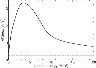
In Fig. 2 the calculated spectral distribution (7) of the channeling radiation in straight Si(110) crystal (solid curve) is compared with the spectral intensity in an amorphous silicon (dashed curve) obtained within the Bethe-Heitler (BH) approximation (see, for example, Ref. Tsai1974 ). It is seen that the intensity of radiation in the oriented crystal greatly exceeds (in the maximum located at MeV there is an order of magnitude excess) that in the amorphous medium. The enhancement is due to the emission by the particles moving along quasi-periodic channeling trajectories, which bear close resemblance with the undulating motion. As a result, constructive interference of the waves emitted from different but similar parts of the trajectory increases the intensity.
Spectral enhancement factor, i.e. the spectral distribution of radiation emitted in the crystalline medium normalized to that in amorphous silicon, calculated for 855 MeV electrons is presented in Fig. 3. Solid curve represents the dependence obtained for straight Si(110), two other curves stand for uniformly bent channel: the broken curve corresponds to cm, the chained one – to cm.
Let us note several specific features of the emission spectra formed in bent channels.
First, the bending gives rise to the synchrotron radiation, since the channeled particle experiences the circular motion in addition to the channeling oscillations. This leads to the increase of the intensity in the photon energy range keV. For these energies the radiation yield from the bent channel exceeds that from the straight channel.
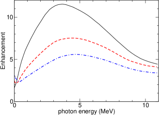
Second, there is a noticeable decrease in the intensity of the channeling radiation with the decrease of the bending radius. The ratio of the maximum value of the spectrum in the bent channel to that in the straight one is for cm and for cm. The statistical uncertainties of these values due to the finite number of the simulated trajectories is on the level of 10 per cent. The decrease of can be explain as follows. In the vicinity of the maximum, the main contribution to the channeling radiation intensity comes from those segments of a trajectory where the particle stays in the same channel experiencing channeling oscillations. The intensity of radiation emitted from either of this segments and integrated over the emission angles is proportional to the segment length and to the square of the undulator parameter associated with the channeling oscillations. The undulator parameter is related to the mean square of the transverse velocity: (see, e.g., Baier ). Then, to estimate the right-hand side of Eq. (7) one can consider the contribution to the sum coming from the primary channeling segments. Hence
| (10) |
For bending radii much larger than the critical radius the factor depends weakly on . Hence, the factor , defined above, can be calculated at the ratio of the products calculated for the bent and the straight channels. Using the data from Table 1 one estimates: and for and 1.3 cm, respectively. These values correlate with the ones quoted above. Thus, the decrease in the acceptance and in the penetration length with is the main reason for lowering the intensity of channeling radiation.
Finally, comparing the curves in Fig. 3 one notices that the position of the maximum shifts to higher photon energies with the growth of the crystal curvature . This feature is specific for the electron channeling (more generally, for channeling of negatively charged projectiles) and is due to strong anharmonicity of the channeling oscillations. As a result, the frequency of the oscillations varies with the amplitude . Typically, smaller vales of correspond to larger frequencies (see, for example, the results of simulations presented in Sub_GeV_2013 ). As the curvature increases, the allowed values of decrease due to the action of the centrifugal force BiryukovChesnokovKotovBook . Hence, on average, the frequency of the channeling increases and so does the frequency of the emitted photons .
The spectra presented in Figs. 2 and 3 are obtained from Eq. (7) by averaging over all simulated trajectories. The main contribution to the radiation enhancement comes from the electrons which stay mostly in the channeling regime. In this context it is of interest to analyze the spectral distribution of radiation produced only by electrons propagating through the whole bent crystal staying in a single channel or in a few different channels (i.e. changing the channels due to the rechanneling effects). Such trajectories, although being quite rare, allow one to visualize the influence of the channeling oscillations as well as of the rechanneling effect on the synchrotron-like part of the spectrum.
To carry out this program we analyzed electron trajectories simulated in m Si(110) crystal bent with the radius cm. Fifteen trajectories (”group 1”) were found corresponding to the motion through the whole crystal staying in the same channel in which the projectile was captured at the entrance. Another twelve trajectories (”group 2”) were comprised of several channeling segments of the total length . Examples of these trajectories (from the both groups) one finds in Fig. 1. The radiation spectra, averaged over each group of electrons, are represented in Fig. 4 by solid curves labeled with ”1” and ”2”. At MeV both curves have the maxima corresponding to the channeling radiation. It is not surprising that the enhancement factor averaged over the specially selected trajectories is much larger than the one averaged over all trajectories, see broken curve in Fig. 3.
The increase of the enhancement factor at small photon energies is associated with the synchrotron radiation. To visualize this we calculated the spectral distribution of radiation due to motion along a arc of a circle of the radius 1.3 cm, i.e. along the bent channel centerline ignoring the channeling oscillations. The result, normalized to the Bethe-Heitler spectrum, is presented in Fig. 4 by the broken line. Within the statistical errors (not indicated) the curves 1 and 2 coincide with the synchrotron spectrum at MeV.
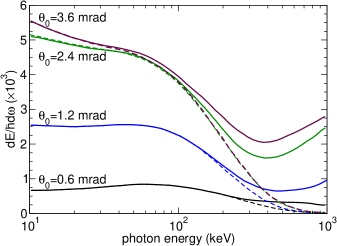
In Ref. Sub_GeV_2013 the influence of the detector aperture on the form of the spectral distribution of the channeling radiation in straight and bent Si(110) channels was explored. In Fig. 5 we present results of the similar analysis of the low-energy part of the spectrum. Full curves correspond to the spectra (7) averaged over the simulated trajectories corresponding to the motion through the whole crystal staying in the same channel (”group 1”). Broken curves represent the distribution of the synchrotron radiation due to the motion along the circle arc. The calculations were performed for = 0.6, 1.2, 2.4 and 3.6 mrad which are integer multiples of the natural emission angle mrad. The latter characterizes the cone (along the instantaneous velocity) which accumulates most of the radiation emitted by an ultra-relativistic projectile.
Two features of the presented dependences can be mentioned.
First, it is seen that the intensity is quite sensitive to the detector aperture. This effect is more pronounced for the lower values of and within the keV photon energy range where most of radiation is emitted via the synchrotron mechanism. For example, a two-fold change in the aperture from to results in a nearly four-fold increase of the intensity at in the lowest-energy part of the spectrum. Such a behaviour can be understood if one compares the quoted values of with the angle of rotation of the bent crystal centerline, mrad. For apertures smaller than the radiation within the cone along the incident velocity will be effectively emitted only from the initial part of the crystal, the length of which can be estimated as . Thus, the raise of the aperture from to mrad results in the two-fold increase of which, in turn, leads to additional augmentation of the emitted intensity. This effects becomes less pronounced for larger apertures, , which collects virtually all radiation emitted within .
Another feature to be mentioned is that the influence of the channeling motion on the emitted spectrum becomes more pronounced over wider range of photon energies with the increase of the aperture. Indeed, the deviation of the total emission spectrum (full curves) from the spectrum of synchrotron radiation (broken curves) starts at keV for mrad but at keV for mrad. To explain this one recalls that channeling motion bears close resemblance with the undulating motion. As a result, constructive interference of the waves emitted from different but similar parts of the trajectory increases the intensity. For each value of the emission angle the coherence effect is most pronounced for the radiation into harmonics. The frequency of the lowest (first) harmonic can be estimated as (see, e.g., Baier ). Anharmonicity of the electron channeling oscillations results in the variation of along the trajectory. Therefore, the radiation will be emitted within some frequency band which will form the main peak in the spectral distribution of the channeling radiation (see Fig. 2). For small apertures, when , the emission of low-energy photons with is strongly suppressed. For larger apertures a big part of energy is radiated into the cone . For the harmonic energy is strongly red-shifted . As a result, the contribution of the channeling radiation to the low-energy part of the spectrum increases with the aperture.
3.2 Emission Spectra for m
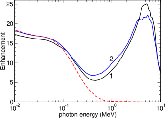
For m thick Si(110) crystal the trajectories were simulated for a wider range of the bending radius (in addition to the values indicated in Table 1 the calculations were performed for cm, see Ref. BentSilicon_2013 ). The results of calculations of the enhancement factor obtained for the aperture mrad are presented in Figs. 6 and 7.
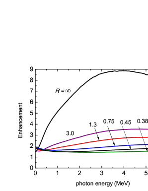
Figure 6 illustrates the modification of the spectral dependence of the enhancement factor in the vicinity of the maximum of channeling radiation. Comparing the presented dependences with those calculated for a shorter crystal, see Fig. 3, one can state that in both cases the profiles of the enhancement factor are similar, and the maximum values of the enhancement factor are close in both cases. In both figures there are two curves calculated for the same values of the bending radius: (straight crystal) and cm. Comparing these one notices that the maximum values are larger (by factors and , respectively) for a shorter crystal. To explain this one can use the following arguments. In a straight crystal, the intensity of channeling radiation is proportional to the total length of the channeling segments, , whereas the intensity of the incoherent bremsstrahlung scales with the crystal length . Hence, the enhancement factor is proportional to . For a m thick crystal m (see Table 1). For m we found m. Hence the ratio of the values calculated for and m straight Si(110) crystals is which correlates with the factor quoted above. Similar arguments can be applied to the case of a bent crystal. The only difference is that the intensity of the background bremsstrahlung radiation integrated over the aperture is proportional to the effective length .
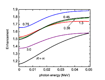
The synchrotron radiation influences the total spectrum in the photon energy range well below the maximum of channeling radiation. Fig. 7 illustrates the behaviour the enhancement factor in the low-energy part of the spectrum.
It is seen from the figure that the enhancement due to the synchrotron radiation is a non-monotonous function of the bending radius. At small curvatures the enhancement increases with . The maximum values are achieved at cm and then the enhancement decreases with the curvature. This feature is due to the finite aperture which for sufficiently small values of introduces the length of the crystal where the radiation detected within the cone is effectively formed, and thus reduces the enhancement.
4 Conclusion
Using a newly developed code NewPaper_2013 , which was implemented as a module in the MBN Explorer package MBN_ExplorerPaper , we have performed numerical simulations of trajectories of ultra-relativistic electrons in oriented straight and bent single Si(110) crystals.
The simulated trajectories were used as the input data for numerical analysis of the intensity of the emitted radiation. In the case of straight crystals the channeling radiation appears atop the incoherent bremsstrahlung background. In a bent channel the spectrum is enriched by the synchrotron radiation due to the circular motion of the projectile along the bent centerline.
The calculation of the spectra as well as the numerical analysis of channeling conditions and properties (acceptance, dechanneling length) have been carried out for the beam of 855 MeV electrons for two lengths of Si crystal. The obtained and presented results are of interest in connection with the ongoing experiments with electron beams at Mainz Microtron Backe_EtAl_2011 .
5 Acknowledgments
We are grateful to Hartmut Backe and Werner Lauth for fruitful and stimulating discussions. The work was supported by the European Commission CUTE-IRSES project (grant GA-2010-269131). The possibility of performing complex computer simulations at the Frankfurt Center for Scientific Computing is gratefully acknowledged.
References
- (1) G.B. Sushko, V.G. Bezchastnov, I.A. Solov’yov, A.V. Korol, W. Greiner, A.V. Solov’yov, J. Comp. Phys. 252, 404-418 (2013)
- (2) I.A. Solov’yov, A.V. Yakubovich, P.V. Nikolaev, I. Volkovets, A.V. Solov’yov, J. Comp. Chem. 33, 2412–2439 (2013)
- (3) http://www.mbnexplorer.com/
- (4) J. Lindhard, K. Dan. Vidensk. Selsk. Mat. Fys. Medd. 34, 1-64 (1965)
- (5) E.N. Tsyganov, Fermilab Preprint TM-682 (Fermilab, Batavia, 1976); Fermilab Preprint TM-684 (Fermilab, Batavia, 1976)
- (6) M.A. Kumakhov, Phys. Lett. 57A, 17-18 (1976)
- (7) Channeling and other crystal effects at relativistic energy, edited by H.H. Andersen, L.E. Rehn, Nucl. Instrum. Methods Phys. Res. B 119 (Topical Issue), 1-315 (1996)
- (8) J.U. Andersen, E. Bonderup, R.H. Pantell, Annu. Rev. Nucl. Part. Sci. 33, 453-504 (1983)
- (9) J. Bak, J.A. Ellison, B. Marsh, F.E. Meyer, O. Pedersen, J.B.B. Petersen, E. Uggerhøj, K. Østergaard, Nucl. Phys. B 254, 491-527 (1985)
- (10) J. Bak, J.A. Ellison, B. Marsh, F.E. Meyer, O. Pedersen, J.B.B. Petersen, E. Uggerhøj, S.P. Møller, H. Sørensen, M. Suffert, Nucl. Phys. B 302, 525–558 (1988)
- (11) V.A. Bazylev, N.K. Zhevago, Sov. Phys. Usp. 25, 565–595 (1982)
- (12) Relativistic Channeling, edited by A. Carrigan, J. Ellison (Plenum, New York, 1987)
- (13) M.A. Kumakhov, F.F. Komarov, Radiation from Charged Particles in Solids (AIP, New York, 1989)
- (14) A.W. Saenz, H. Überall, Nucl. Phys. A372, 90–108 (1981)
- (15) E. Uggerhøj, Radiat. Eff. Defects Solids 25, 3–21 (1993)
- (16) Uggerhøj, U.I. Rev. Mod. Phys. 77, 1131–1171 (2005)
- (17) U.I. Uggerhøj, Doctoral Dissertation, Department of Physics and Astronomy, University of Aarhus, Denmark, 2011, http://www.phys.au.dk/ ulrik/Doct_dis_UIU.pdf
- (18) V.V. Kaplin, S.A. Vorobev, Phys. Lett. 67A, 135–137 (1978)
- (19) Yu.A. Bashmakov, Radiat. Eff. 56, 55–60 (1981)
- (20) A.M. Taratin, S.A. Vorobiev, Nucl. Instrum. Method Phys. Res. B 31, 551–557 (1988)
- (21) A.M. Taratin, S.A. Vorobiev, Nucl. Instrum. Method Phys. Res. B 42, 41–45 (1989)
- (22) V.A. Arutyunov, N.A. Kudryashov, M.N. Strikhanov, V.M. Samsonov, Sov. Phys. Tech. Phys. 36, 1–3 (1991)
- (23) V.A. Arutyunov, N.A. Kudryashov, V.M. Samsonov, M.N. Strikhanov, Nucl. Phys. B 363, 283–300 (1991)
- (24) A.M. Taratin, Phys. Part. Nucl. 29, 437–462 (1998)
- (25) A.V. Solov’yov, A. Schäfer, W. Greiner, Phys. Rev. E 53, 1129–1137 (1996)
- (26) L.D. Landau, E.M. Lifshitz, Course of Theoretical Physics, vol.2: The Classical Theory of Fields (Pergamon Press, Oxford, 1971)
- (27) J.D. Jackson, Classical Electrodynamics (Wiley, Hoboken, New Jersey, USA, 1999)
- (28) V.M. Biryukov, Yu.A. Chesnokov, V.I. Kotov, Crystal Channeling and its Application at High-Energy Accelerators (Springer-Verlag, Berlin, Heidelberg, 1996)
- (29) A.V. Korol, A.V. Solov’yov, W. Greiner, J. Phys. G Nucl. Part. Phys. 24, L45-L53 (1998)
- (30) A.V. Korol, A.V. Solov’yov, W. Greiner, Int. J. Mod. Phys. E 8, 49–100 (1999)
- (31) A.V. Korol, A.V. Solov’yov, W. Greiner, Channeling and Radiation in Periodically Bent Crystals (Springer-Verlag, Berlin, Heidelberg, 2013)
- (32) V.T. Baranov, S. Bellucci, V.M. Biryukov et al, Nucl. Instrum. Method Phys. Res. B252, 32-35 (2006)
- (33) H. Backe, D. Krambrich, W. Lauth, B. Buonomo, S.B. Dabagov, G. Mazzitelli, L. Quintieri, J.L. Hansen, U.K.I. Uggerhøj, B. Azadegan, A. Dizdar, W. Wagner, Nuovo Cimento C 34, 175-180 (2011)
- (34) H. Backe, P. Kunz, W. Lauth, A. Rueda, Nucl. Instrum. Method Phys. Res. B 266, 3835–3851 (2008)
- (35) H. Backe, D. Krambrich, W. Lauth, J.L. Hansen, U.K.I. Uggerhøj, Nuovo Cimento C 34, 157–165 (2011)
- (36) H. Backe, W. Lauth, P. Kunz, A. Rueda, J. Esberg, K. Kirsebom, J.L. Hansen, U.K.I. Uggerhøj, in Proceedings of the 51st Workshop Charged and Neutral Particles Channeling Phenomena Channeling 2008, Erice, Italy, Oct 2008 edited by S.B. Dabagov, L. Palumbo, A. Zichichi, (World Scientific, Singapore/Hackensack 2010), p. 281–290
- (37) H. Backe, D. Krambrich, W. Lauth, K.K. Andersen, J.L. Hansen and U.I. Uggerhoj Journal of Phys.: Conf. Series 438, 012017 (2013)
- (38) U. Mikkelsen, E. Uggerhøj, Nucl. Instrum. Method Phys. Res. B 160, 435–439 (2000)
- (39) W. Krause, A.V. Korol, A.V. Solov’yov, W. Greiner, Nucl. Instrum. Method Phys. Res. A 483, 455–460 (2002)
- (40) https://portal.slac.stanford.edu/sites/ard_public/facet /research/Pages/CurrentResearch.aspx
- (41) G.B. Sushko, V.G. Bezchastnov, A.V. Korol, W. Greiner, A.V. Solov’yov, R.G. Polozkov, V.K. Ivanov, J. Phys.: Conf. Ser. 438, 012019 (2013)
- (42) G.B. Sushko, A.V. Korol, W. Greiner, A.V. Solov’yov, J. Phys.: Conf. Ser. 438, 012018 (2013)
- (43) A. Kostyuk, A.V. Korol, A.V. Solov’yov, W. Greiner, J. Phys. B At. Mol. Opt. Phys. 44, 075208 (2011)
- (44) V.N. Baier, V.M. Katkov, V.M. Strakhovenko, Electromagnetic Processes at High Energies in Oriented Single Crystals (World Scientific, Singapore 1998)
- (45) D.S. Gemmell, Rev. Mod. Phys. 46, 129–227 (1974)
- (46) A. Kostyuk, Eur. Phys. J. D 67, 108 (2013)
- (47) V.N. Baier, V.M. Katkov, Zh. Eksp. Teor. Fiz. 53, 1478–1491 (1967) (English translation: Sov. Phys. – JETP 26, 854–860 (1968))
- (48) Y-S. Yung-Su Tsai, Rev. Mod. Phys. 46, 815–851 (1974)