Transmittance of a subwavelength aperture flanked by a finite groove array
placed near the focus of a conventional lens
Abstract
One-dimensional light harvesting structures illuminated by a conventional lens are studied in this paper. Our theoretical study shows that high transmission efficiencies are obtained when the structure is placed near the focal plane of the lens. The considered structure is a finite slit-groove array (SGA) with a given number of grooves that are symmetrically distributed with respect to a central slit. The SGA is nano-patterned on an opaque metallic film. It is found that a total transmittance of 80 % is achieved even for a single slit when (i) Fabry-Perot like modes are excited inside the slit and (ii) the effective cross section of the aperture becomes of the order of the full width at half maximum of the incident beam. A further enhancement of 8 % is produced by the groove array. The optimal geometry for the groove array consists of a moderate number of grooves () at either side of the slit, separated by a distance of half the incident wavelength . Grooves should be deeper (with depth ) than those typically reported for plane wave illumination in order to increase their individual scattering cross section.
pacs:
73.20.Mf, 78.67.-n, 41.20.JbI Introduction
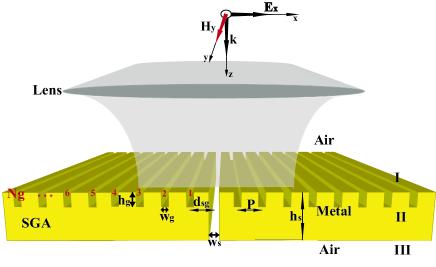
Nanostructured metal films have important applications in sensing and photodetection due to their ability to collect and manipulate light at the nanoscale Thio et al. (2002); Ditlbacher et al. (2002); Ozbay (2006); García-Vidal et al. (2010). For instance, the high local density of states achieved inside a single hole can boost the fluorescence of molecules localized in the reduced volume of the hole Rigneault et al. (2005); Wenger et al. (2008). A single aperture drilled on an opaque metal film can be surrounded by periodic structures, like in the slit-groove array (SGA) shown in Fig. 1, to efficiently harvest light and subsequently squeeze it through the aperture. The surface corrugation acts like an antenna that couples the incident light into surface modes, which are responsible for squeezing the EM energy into the aperture García-Vidal et al. (2010). The light harvesting process can be made more efficient by increasing the size of the system, provided that it does not exceed the propagation length of the surface modes. As a consequence of the light harvesting process, the power radiated to the farfield can be one or two orders of magnitude larger than the power impinging on the aperture Thio et al. (2001); Lezec et al. (2002); Hibbins et al. (2002); García-Vidal et al. (2003); Akarca-Biyikli et al. (2004); Thomas and Hughes (2004); Janssen et al. (2007); Villate-Guío et al. (2012). The metal can also be sculpted on the exit surface to modify the re-emission pattern emerging from the aperture, leading to the beaming phenomenon Lezec et al. (2002); Martín-Moreno et al. (2003). Phase compensation mechanisms produced by the outer corrugation allow the design of novel kind of lenses Fang et al. (2005); Liu et al. (2007); Smolyaninov et al. (2007); Ma and Liu (2010); Lu and Liu (2012). The quasi-two dimensional nature of all such structures paves the way to its integration into optoelectronic devices with levels of miniaturization and operational speeds that could be never achieved with standard electronics Collin et al. (2003); Ishi et al. (2005); Yu et al. (2006); Laux et al. (2008); Dunbar et al. (2009); Stanley (2012).
A key feature of the optical response of a subwavelength single slit is that its effective cross section () is larger than the aperture size () García-Vidal et al. (2010), which means that the aperture transmits more light than the one impinging directly on it. Even an infinitesimal narrow slit at resonance in a perfect electric conductor (PEC) film has a large Harrington and Auckland (1980), which is of the order of the wavelength of the incident radiation.
It is usually assumed in theoretical calculations that the system is illuminated by a plane wave (PW), in accordance with the broad wave front used in typical experimental conditions. In this paper we analyze the case that the PW front is focused with help of a conventional lens. Thanks to its macroscopic dimensions, the lens collects an amount of energy several orders of magnitude larger than the one impinging directly on the aperture and focuses such energy in a spot with size of the order of the wavelength. When the size of the focus and the effective cross section of the aperture are of the same order, a large total transmittance () is expected for the new illumination conditions. However, to the best of our knowledge, this way of illuminating the system has not been examined previously.
The first goal of this paper is to show the enhancement of when a subwavelength aperture is located at the focal plane of a lens. Furthermore, the density of EM energy near a subwavelength aperture provided by the lens is so high that one should wonder if a further enhancement of is still possible. Therefore, the second goal of this paper is to show that a groove array can increase the total amount of light transmitted through the aperture, even in the case that only a small fraction of the groove array is illuminated by the central spot of the lens. Moreover, the sensitivity to the position of the SGA with respect to the focus of the lens is studied. We also provide ideal geometries for achieving high transmission intensities by optimizing the system shown in Fig. 1 under the new illumination conditions.
II Theoretical framework
Figure 1 describes the geometry of the system under study: a SGA illuminated by a cylindrical lens with focal distance . We assume that a -polarized plane wave of wavelength and electric field , parallel to the axis, impinges perpendicularly on a thin cylindrical lens fixed at , see Fig. 1. The fields of the lens are computed adapting the general method presented in Ref. Novotny and Hecht (2006) to the case of a cylindrical lens. This method consists in two main steps: (i) the fields near the optical lens are formulated by the rules of geometrical optics within the paraxial approximation Goodman (2004) and (ii) the lens fields are rigorously propagated to an arbitrary plane at the far-field by the means of the angular spectrum representation Novotny and Hecht (2006). In this way, the non-vanishing components of the EM fields parallel to the metal plane can be written as
| (1) | |||||
where , is the wave number of the incident wave, is the admittance of the propagating fields, and . The perpendicular component of the electric field, , can be derived from Maxwell’s equations. As we are computing the fields in the far-field of the lens, the above integrals are limited to propagating states . The fields are normalized to render a unity total power behind the lens,
It is straightforward to compute the intensity of the -component of the electric field at the focal plane (),
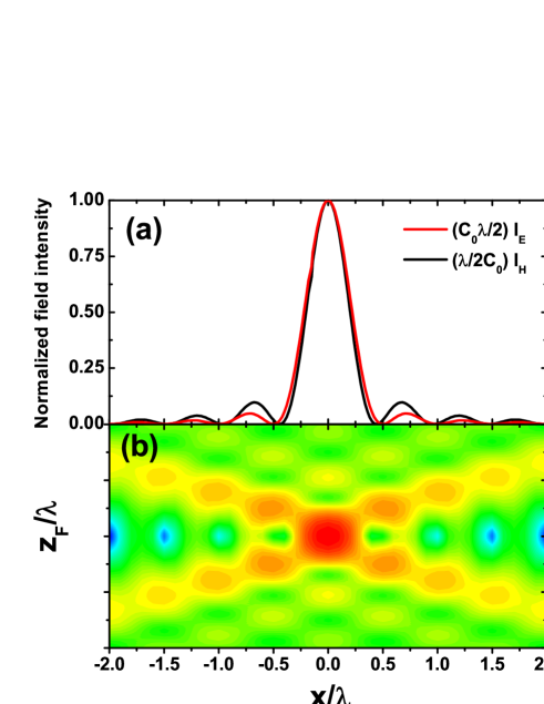
where the function . This quantity has an absolute maximum equal to at , secondary maxima at , and vanishes at the points , where is an integer different from zero. The width of the main peak, defined as the distance between the two first minima, is equal to . The normalized intensity at the focal plane, , is represented in Fig. 2(a).
The intensity of at the focus is . It is 56 % larger than . at other points of the focal plane has a more cumbersome expression that must be evaluated numerically. In contrast with PW illumination, and are no longer proportional after traversing the lens, although their normalized intensities show similar features, see Fig. 2(a). It is worth to notice, however, that the minima of are slightly shifted to .
Fig. 2(b) shows the intensity of the -component of the magnetic field (in a logarithmic scale) in a region near the focus. The position relative to the focal plane is labeled as . Out of focus, the main peak is broader and has an intensity lower than at the focal point, although the minima at show now a non-zero intensity.
The optical response of the system is computed in the framework of the coupled mode method (CMM) García-Vidal et al. (2010), which is briefly reviewed here for the sake of completeness. The CMM is based on a convenient representation of the EM fields in each region (waveguide modes and plane waves are used inside the defects and in the space surrounding the metal film, respectively).
The metal is treated as a PEC. This approximation captures the main trends of the response of a metal at optical frequencies, is a good approximation in the infrared part of the spectrum, and provides practically exact results for the THz regime García-Vidal et al. (2010); Villate-Guío et al. (2012). A generalization of the results for the case of a real metal is straightforward de León-Pérez et al. (2008) and does not change the main conclusions at which we arrive in the paper.
For a subwavelength aperture, convergence is rapidly achieved with a small number of waveguide modes, with the fundamental-mode approximation already showing an excellent agreement with fully converged results López-Tejeira et al. (2008). Therefore, only the fundamental propagating eigenmode of a planar waveguide is considered for slit and grooves, i.e. the electric field inside the indentation is a linear combination of , with and for the slit and the identical grooves, respectively.
After matching the fields at the interfaces, the matching equations can be expressed as a function of the set , which gives the amplitude of the waveguide modes right at the indentation openings: at the output side of the slit and at the input side of slit () and grooves (, , , ). After some straightforward algebra, we end up with the following set of equations for the unknowns García-Vidal et al. (2003):
| (2) |
The function takes into account the bouncing back and forth of the electromagnetic fields inside the defects. represents the coupling between the fields at the two sides of the slit. is the projection onto wavefields and of the green function , being the Hankel function of the first kind García-Vidal et al. (2010). The term in Eq. (2) can be viewed as the reillumination of indentation by the EM field coming from indentation , while is a self-interaction term.
Only the independent term is a function of the field provided by the lens. It gives the direct illumination over defect , centered at the position . is proportional to the overlap of the waveguide mode and the incident EM field, and reads
where . For a very narrow aperture () located at the focal plane, the illumination is proportional to the magnetic field, . At the focus, it simplifies to
| (3) |
Finally, the total transmittance is defined as the ratio of the energy power radiated to the far-field and the total incident power . can be cast in a simple analytical form García-Vidal et al. (2010)
| (4) |
where is the complex conjugate of . The effective cross section of a slit of width is defined as
| (5) |
where is power incident directly on the slit. For the particular case of infinitesimal slit at the focus, it is straightforward to compute the incident power, ; therefore
| (6) |
III Single Slit
In this section we study the optical response of a single slit of width drilled in a PEC film with thickness . The spectral locations of its characteristic transmission peaks are associated with the resonant condition
| (7) |
see Ref. García-Vidal et al. (2010). It gives rise to Fabry-Perot (FP) like modes, which are independent of the way the system is illuminated. We consider first the extreme subwavelength regime for the slit, . In this limiting case, FP modes occur when the metal thickness is an integer multiple of half the wavelength, García-Vidal et al. (2003). As mentioned above, an infinitesimally narrow slit has a large () effective cross section when it is at resonance. This expression was first reported in Ref. Harrington and Auckland (1980) and later re-derived in the framework of the CMM García-Vidal et al. (2010) by taking the limit in Eq. (2).
PW illumination has been assumed in those previous calculations. However, when the incident light is focused by the lens on the infinitesimal aperture, a closed-form expression can be derived for the total transmittance. We start from the general expression for the total transmittance at resonance
derived in Ref. García-Vidal et al. (2010) for the extreme subwavelength regime. It was obtained using the resonant condition (7) in Eq. (4) and taking the limit in the expression for . Assuming that the infinitesimal slit is at the focal point of the lens () and using Eq. (3) for , we find that
Such large value of , which is independent of both and for a very narrow aperture, is the main result of this paper. We recall that, in contrast with this 80% of efficiency, the total transmittance for a PW impinging directly on metal surface is vanishing small due to the infinite extension of its wave front. In practice, the PW transmittance should be normalized to the power incident on a finite area, like the area of the aperture García-Vidal et al. (2010).
The enhancement of can be explained by the large effective cross section of the slit, which is easily obtained after replacing in Eq. (6),
| (8) |
It approaches the full width at half maximum (FWHM) of the intensity of the incident field, which is equal to FWHM in Fig. 2(a). Such small increment of 25 % with respect to is enough to allow that a 80 % of the focused light can be transmitted through the aperture.
All previous analytical results have been derived for a very narrow subwavelength aperture with . We study now a finite subwavelength slit with a typical experimental width, . For , FP-like modes at fixed are excited in thinner metal films, Takakura (2001). So we get a resonant thickness of for and .
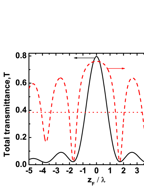
Fig. 3 shows both and as a function of for such slit. At the focal point, we have that and . Such values are slightly larger than (but in excellent agreement with) those obtained for an infinitesimal aperture. The difference is on the second decimal place. Notice that for the finite slit under PW illumination is slightly smaller than for an infinitesimally narrow slit. We find . This value is represented with a red-dotted horizontal line in Fig. 3.
As a function of , shows a main peak at the focal plane of the lens () and secondary peaks of lower intensity when the slit is out of focus. This behavior can be explained by the non-monotonous dependence of the magnetic field incident on the slit. Extreme values of both and occur at the same , c.f. Figs. 2(b) and 3(a). The oscillation of around the constant value for PW illumination can be explained in a similar way.
IV Slit-groove array
We study now the total transmittance of a SGA near the focal plane of the lens. We assume that all grooves are identical, with depth , width , period , and distance from the first groove to the central slit. As in Fig. 3, we consider a metal film with thickness and a slit of width centered at the principal axis of the lens.
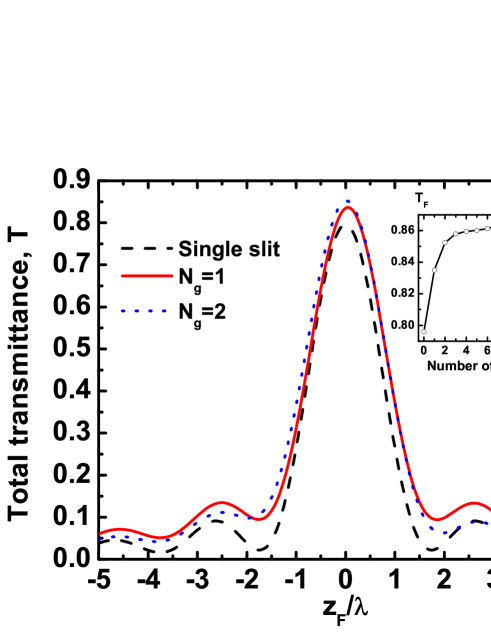
Fig. 4 shows as a function of , near the focal region, for a SGA with (black-dashed line), 1 (red-solid line), and 2 (blue-dotted line) grooves at either side of the central slit. The inset shows the transmittance at the focus () as a function of the number of grooves .
The response of the system has been optimized for providing a high transmission intensity when it is placed at . In the optimization process, we can follow design rules similar to those developed in Ref. Villate-Guío et al. (2012) for PW illumination. Thus, the largest transmittance is obtained when the Fabry-Perot mode of the slit (discussed in the previous section) is located at the same spectral position than the mode excited in the groove array García-Vidal et al. (2003). The mode in the array is a function of the groove geometry, its optimal periodicity guarantees that the light re-emitted by the grooves reaches in phase the other grooves and the central slit. The interaction between the slit and the groove array can be further controlled by modifying .
The main difference we find with respect to the optimal response for PW illumination is that groove cavity modes are not excited when the grooves are illuminated by the lens. Cavity modes for a groove with an infinitesimal width () are obtained for a groove depth equal to , where is an integer García-Vidal et al. (2003). For a finite width, the first order groove cavity mode appears for Villate-Guío et al. (2012); when tends to zero, the ideal approaches from below. However, in the presence of the lens, the first order mode for a finite width is found for , so the groove cavity mode is not excited. Moreover, when tends to zero, the ideal approaches from above. Grooves need to be deeper than in the case of PW illumination in order to increase their scattering cross section. In this way, the groove compensate the reduction of the intensity of the incident light out of focus, see Fig. 2(a). On the other hand, we find that, for an optimal reillumination of the central slit, the distance between neighboring grooves should be of the order of (see the discussion below). A set of geometrical parameters that satisfies all such requirements are given in the caption of Fig. 4.
We observe in Fig. 4 that the intensity of the main peak for the SGA is larger than for a single slit. Moreover, increases with the number of grooves. An enhancement of 8 % with respect to the single slit is found. However, is saturated for a moderate number of grooves; practically not further enhancement is found for grooves. The intensity of the secondary peaks decreases with for . However, the main peak shows an intensity that is still equal to at . Its FWHM= is practically independent of when grooves.
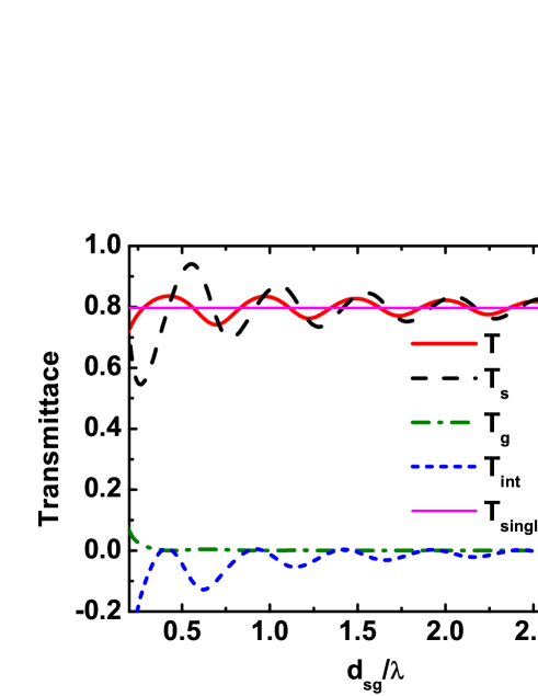
In order to gain physical inside, we make a careful analysis of the transmittance of the SGA with . For this simple case (only two identical grooves are interacting with the central slit), closed-form expressions for the amplitudes of electric field at the input and output sides of the slit, and , respectively, can be easily found by solving the system of Eqs. (2). Replacing both and in Eq. 4, the total transmittance can be written as
| (9) |
where is the transmittance when only the central slit is illuminated (), is obtained when only the grooves are illuminated (), and is an interference term.
Fig. 5 shows at , as well as its constituents terms, as a function of for a SGA with . We find that the slit receives most of the light directly from the lens, while only a small fraction is coming from the grooves (). In fact, decays very fast with , being practically negligible for . The oscillation of is related to the conditions of interference for the reillumination process. A similar behavior has been already reported in Refs. Hibbins et al. (2002); Sönnichsen et al. (2000); Schouten et al. (2005); Lalanne et al. (2005); Alarverdyan et al. (2007); Pacifici et al. (2008); Häfele et al. (2012). The oscillation of has a similar origin. is in antiphase with , leading to a total transmittance that oscillates around the value obtained for a single slit. As a result of the interference between slit and grooves, we find that the ideal positions of the grooves are those located near the minima of the incident field, , see Fig. 2.

Finally, it is worth to stress that a SGA optimized for PW illumination renders a poor response at the focal plane of the lens. Figure 6 illustrates this behavior for a SGA with 6 grooves at each side of the slit. Optimal geometric parameters are given in the figure caption. Grooves optimized for PW illumination have and are shallower than those previously optimized at the focal plane of the lens, c.f. the geometries reported in Figs. 6 and 4.
In order to characterize the response of the SGA when it is placed off focus, we define the ratio . It is equal to when the SGA optimized for PW illumination is illuminated by a PW (in this case is normalized to the power incident on the size of the system). Figure 6 shows for the same system but near the focus of the lens and compares this curve with the constant value . Notice that both the numerator and the denominator of vary now with .
We observe that near the focal region, having a deep minimum at , see inset to Fig. 6. Looking back at the field impinging on the SGA, see Fig. 2, we find that when the SGA is near the focus most of the grooves are outside the hot spot of the lens, so the light collected by them is not enough to achieve the same efficiency than for a SGA illuminated with a PW. Moreover, at the focus, i.e. the SGA optimized to operate under PW illumination, when placed at the focus of a lens, is less efficient than a single slit under the same illumination. Oscillations in (see inset) are due to the non-uniform illumination provided by the lens.
By moving the SGA out of focus, the incident light reaches more grooves and therefore starts to raise. reaches its maximum value when the whole SGA is illuminated by the lens. Notice, however, that at such large relative distance is rather small due to the reduction of the power directly incident on the slit. Far away from the focus, the hot spot is so broad that it behaves like a plane wave and tends to .
V Conclusions
We have studied the optical response of a slit-groove array illuminated by a conventional cylindrical lens. The lens enlarges the effective cross section of the central slit by focusing the incident radiation on its opening. An effective cross-section 25 % larger than for plane-wave illumination together with the confinement of the incident field leads to a total transmittance at the focus % for the single slit. An optimal groove array further enhances in 8 %. The transmittance decreases with the distance relative to the focal plane ; however, at a distance to the focus , is still equal to . Moreover, we have found that a slit-groove array optimized far away from the focus (i.e. for PW illumination) renders a low efficiency when it is at the focal plane of a lens.
The ideal geometry of the slit allows that the well known Fabry-Perot like modes are excited inside it. Grooves should be deeper (with depth ) than those typically reported for PW illumination in order to increase their scattering cross section. A moderate number of grooves () is needed for achieving high intensities. The ideal distance between grooves is close to for PW illumination. However, grooves should be separated by a distance of at the focal plane of the lens.
We hope that the present work could motivate further experimental and theoretical studies of the interaction of a SGA with both conventional lenses and metalenses, as well as future applications in the design of optical and infrared detectors.
Acknowledgements.
The authors gratefully acknowledge financial support by European Projects EC FP7-ICT PLAISIR Project Ref. 247991 and the Spanish Ministry of Science and Innovation project MAT2011-28581-C02-02.References
- Thio et al. (2002) T. Thio, H. J. Lezec, T. W. Ebbesen, K. M. Pellegrin, G. D. Lewen, A. Nahata, and R. A. Linke, Nanotechnology 13, 429 (2002).
- Ditlbacher et al. (2002) H. Ditlbacher, J. R. Krenn, G. Schider, A. Leitner, and F. R. Aussenegg, Appl. Phys. Lett. 81, 1762 (2002).
- Ozbay (2006) E. Ozbay, Science 311, 189 (2006).
- García-Vidal et al. (2010) F. J. García-Vidal, L. Martín-Moreno, T. W. Ebbesen, and L. Kuipers, Rev. Mod. Phys. 82, 729 (2010).
- Rigneault et al. (2005) H. Rigneault, J. Capoulade, J. Dintinger, J. Wenger, N. Bonod, E. Popov, T. W. Ebbesen, and P. F. Lenne, Phys. Rev. Lett. 95, 117401 (2005).
- Wenger et al. (2008) J. Wenger, D. Gérard, J. Dintinger, O. Mahboub, N. Bonod, E. Popov, T. W. Ebbesen, and H. Rigneault, Opt. Express 16, 3008 (2008).
- Thio et al. (2001) T. Thio, K. M. Pellegrin, R. A. Linke, H. J. Lezec, and T. W. Ebbesen, Optics Letters 26, 1972 (2001).
- Lezec et al. (2002) H. J. Lezec, A. Degiron, E. Devaux, R. A. Linke, L. Martín-Moreno, F. J. García-Vidal, and T. Ebessen, Science , 820 (2002).
- Hibbins et al. (2002) A. P. Hibbins, J. R. Sambles, and C. R. Lawrence, Appl. Phys. Lett. 81, 4661 (2002).
- García-Vidal et al. (2003) F. J. García-Vidal, H. J. Lezec, T. W. Ebbesen, and L. Martín-Moreno, Phys. Rev. Lett. 90, 213901 (2003).
- Akarca-Biyikli et al. (2004) S. Akarca-Biyikli, I. Bulu, and E. Ozbay, Appl. Phys. Lett. 85, 1098 (2004).
- Thomas and Hughes (2004) D. Thomas and H. Hughes, Solid State Communications 129, 519 (2004).
- Janssen et al. (2007) O. T. A. Janssen, H. P. Urbach, and G. W. tHooft, Phys. Rev. Lett. 99, 043902 (2007).
- Villate-Guío et al. (2012) F. Villate-Guío, F. López-Tejeira, F. J. García-Vidal, L. Martín-Moreno, and F. de León-Pérez, Opt. Express 20, 25441 (2012).
- Martín-Moreno et al. (2003) L. Martín-Moreno, F. J. García-Vidal, H. J. Lezec, A. Degiron, and T. W. Ebbesen, Phys. Rev. Lett. 90, 167401 (2003).
- Fang et al. (2005) N. Fang, H. Lee, C. Sun, and X. Zhang, Surf. Sci. 308, 534 (2005).
- Liu et al. (2007) Z. Liu, H. Lee, Y. Xiong, C. Sun, and X. Zhang, Science 315, 1686 (2007).
- Smolyaninov et al. (2007) I. Smolyaninov, Y.-J. Hung, and C. Davis, Science 315, 1699 (2007).
- Ma and Liu (2010) C. Ma and Z. Liu, Appl. Phys. Lett. 96, 183103 (2010).
- Lu and Liu (2012) D. Lu and Z. Liu, Nat. Commun. 3, 1205 (2012).
- Collin et al. (2003) S. Collin, F. Pardo, and J.-L. Pelouard, Applied Physics Letters 83, 1521 (2003).
- Ishi et al. (2005) T. Ishi, J. Fujikata, K. Makita, T. Baba, and K. Ohashi, Japanese Journal of Applied Physics 44, L364 (2005).
- Yu et al. (2006) Z. Yu, G. Veronis, S. Fan, and M. B. L., Appl. Phys. Lett. 89 (2006), 10.1063/1.2360896.
- Laux et al. (2008) E. Laux, C. Genet, T. Skauli, and T. W. Ebbesen, Nature Photonics 2, 161 (2008).
- Dunbar et al. (2009) L. A. Dunbar, M. Guillaumée, F. de León-Pérez, C. Santschi, E. Grenet, R. Eckert, F. López-Tejeira, F. J. García-Vidal, L. Martín-Moreno, and R. P. Stanley, Appl. Phys. Lett. 95, 011113 (2009).
- Stanley (2012) R. Stanley, Nature Photonics 6, 409 (2012).
- Harrington and Auckland (1980) R. F. Harrington and D. T. Auckland, Antennas Propag. IEEE Trans. AP-28, 616 (1980).
- Novotny and Hecht (2006) L. Novotny and B. Hecht, Principles of Nano-optics (Cambridge University Press, New York, 2006).
- Goodman (2004) J. W. Goodman, Introduction to Fourier Optics, edited by Roberts and Company (Roberts and Company, 2004).
- de León-Pérez et al. (2008) F. de León-Pérez, G. Brucoli, F. J. García-Vidal, and L. Martín-Moreno, New J. Phys. 10, 105017 (2008).
- López-Tejeira et al. (2008) F. López-Tejeira, S. G. Rodrigo, L. Martín-Moreno, F. J. García-Vidal, E. Devaux, J. Dintinger, T. W. Ebbesen, J. R. Krenn, I. P. Radko, S. I. Bozhevolnyi, M. U. González, J. C. Weeber, and A. Dereux, New J. Phys. 10, 033035 (2008).
- Takakura (2001) Y. Takakura, Phys. Rev. Lett. 86, 5601 (2001).
- Sönnichsen et al. (2000) C. Sönnichsen, A. C. Duch, G. Steininger, M. Koch, G. von Plessen, and J. Feldmann, Appl. Phys. Lett. 76, 140 (2000).
- Schouten et al. (2005) H. F. Schouten, N. Kuzmin, G. Dubois, T. D. Visser, G. Gbur, P. F. A. Alkemade, H. Blok, G. W. tHooft, D. Lenstra, and E. R. Eliel, Phys. Rev. Lett. 94, 053901 (2005).
- Lalanne et al. (2005) P. Lalanne, J. P. Hugonin, and J. C. Rodier, Phys. Rev. Lett. 95, 263902 (2005).
- Alarverdyan et al. (2007) Y. Alarverdyan, B. Sepúlveda, L. Eurenius, E. Olsson, and M. Käll, Nature Physics 3, 884 (2007).
- Pacifici et al. (2008) D. Pacifici, H. J. Lezec, L. A. Sweatlock, R. J. Walters, and H. A. Atwater, Opt. Express 16, 9222 (2008).
- Häfele et al. (2012) V. Häfele, F. de León-Pérez, A. Hohenau, L. Martín-Moreno, H. Plank, J. R. Krenn, and A. Leitner, Appl. Phys. Lett. 101, 201102 (2012).