Reactive Kinematic Navigation among Moving and Deforming Obstacles with Global Proofs
Abstract
We present a method for guidance of a Dubins-like vehicle with saturated control towards a target in a steady simply connected maze-like environment. The vehicle always has access to to the target relative bearing angle (even if the target is behind the obstacle or is far from the vehicle) and the distance to the nearest point of the maze if it is within the given sensor range. The proposed control law is composed by biologically inspired reflex-level rules. Mathematically rigorous analysis of this law is provided; its convergence and performance are confirmed by computer simulations and experiments with real robots.
1 Introduction
The capability to successfully operate in dynamic and a priori unknown environments is an ubiquitous key requirement to mobile robots. Various scenarios gave rise to a plenty of relevant algorithms under various sets of assumptions, with the focus being on collision avoidance. However despite extensive research, this issue still represents a real challenge in many cases, often because of numerous uncertainties inherent in the scenario and deficiencies in a priory knowledge.
With focus on the planning horizon, available rich variety of algorithms can be classified into global and local planners [14]. Global planners (GP) generate a complete trajectory based on a comprehensive model of the scene, which is built from a priori and sensory data [16]. For dynamic scenes, this approach is exemplified by several techniques (surveyed in e.g., [15, 13]), including state-time space [4, 8, 24], velocity obstacles [6, 15], and nonholonomic planners [23]. Many GP’s can be accompanied with firm guarantees of not only collision avoidance but also achieving a global objective. However GP’s are computationally expensive and hardly suit real-time implementation; NP-hardness, the mathematical seal for intractability, was established for even the simplest problems of dynamic motion planning [1]. A partial cure was offered in the form of randomized path planning architectures [12, 10]. At the same time, all GP’s are hardly troubled by data incompleteness and unpredictability of the dynamic scene, up to failure in generation of an entire plan.
Local planners (LP) iteratively re-compute only a short-horizon path on the basis of sensory data about a nearest fraction of the environment. This reduces the calculation time and dependence on a priory knowledge. Many of the related techniques, such as the dynamic window [27, 7], the curvature velocity [28], and the lane curvature [21] approaches in fact treat the obstacles as static. On the other side, approaches like velocity obstacles [6], collision cones [2], or inevitable collision states [9, 22] assume known and predictable obstacle velocity. However real-world scenarios may involve obstacles whose predictability ranges from full to none [17]. An intermediate approach assumes predictability with uncertainty and involves a model-based estimation of the region that may be occupied by an obstacle in the future and that typically expands as time progresses [15, 32].
In hardly predictable environments, guarantees provided for LP’s up to now are typically confined to collision avoidance, whereas achieving the global objective remains an open issue. Moreover with the exception of [32], safety typically concerns only for a nearest future, whereas its propagation until the very end of the experiment is not guaranteed.
Previous work has shown navigation schemes based on rigorously proven feedback control laws have several advantages over alternatives [30, 31, 25, 26, 11, 18, 19]. This work adopts this design process, however it is applied to a new problem specification.
The body of the paper is organized as follows. Section 2 describes the system, problem setup, and the proposed navigation strategy. Assumptions and controller tuning are discussed in Section 3. Section 5 presents the main results. Section 7 is devoted to simulations and experiments with real robots, whereas Section 8 offers brief conclusions. The proofs are given in Appendices A, B.
The following notations are adopted in the paper.
— the boundary of the moving obstacle ;
— the standard Euclidian inner product in
;
— the standard Euclidian norm in .
2 Problem Setup
We consider a planar point-wise robot traveling in a two-dimensional workspace. The robot is controlled by the time-varying linear velocity whose magnitude does not exceed a given constant . The robot’s position is given by its abscissa and ordinate in the world frame. The objective is to move towards the azimuth given by the unit vector . However pure following the azimuth is impossible since the scene is cluttered with untraversable obstacles , and the robot should always be in the obstacle-free part of the plane .
The obstacles may undergo general motions, including rotations and deformations. We require that any obstacle is bounded by a smooth Jordan curve. Thus we ignore possible inner holes in obstacles on the ground that they cannot affect the robot’s navigation. The obstacles keep their identities: they do not split into parts, do not merge together, and do not collide with each other.
Remark 1
To take the size of the robot into account, a standard hint is to treat the obstacle as if it is enlarged and bounded by a proper equidistant curve. This automatically smoothes the outer cusps of the obstacle if they do exist. The inner cusps can be smoothed via approximation to meet the boundary smoothness requirement.
The robot has a panoramic view on the environment, which view is shadowed by the obstacles. Specifically we assume a reference frame attached to the robot. For any polar angle in this frame, the robot has access to the distance to the nearest obstacle in the direction given by (see Fig. 1(a)): the point with the relative polar coordinates belongs and does not belong to an obstacle if and , respectively. If there is no obstacle in the examined direction, . The desired direction of motion is also accessed via its relative polar angle .
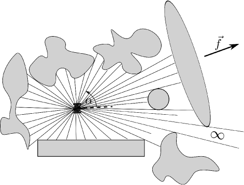
The robot is able to classify enroute obstacles into several disjoint classes , for example, into ‘definitely static’ and ‘probably moving’or into ‘low speed’ and ‘high speed’ obstacles, etc. This setup covers both the case of no classification capacity , where the robot is enforced to treat all obstacles in a common way, and the opposite case where every class contains only one obstacle, which means capability to recognize the obstacles.
By using these data, the robot should move along the given azimuth. Unlike many papers in the area, we do not assume that the obstacles obey a known law of motion. They may move arbitrarily with bounded speeds. The only assumption is that the robot is faster than the obstacles, whose necessity will be justified by Lemma 4.1.
We do not provide specifications of the robot-fixed frame or its evolution over time since these details does not matter in both proposed control law and its analysis.
3 The navigation algorithm
In what follows, we treat angle as a cyclic variable associated with the point on the unit circle.
At time , the scene is given by the function of the polar angle . This function and the angle of are converted into control via the following steps.
-
•
Computation of facets. The discontinuity points of are determined.***Since the obstacles have no inner holes where the robot might appear, such points do exist. They partition the circle into maximal arcs on which is continuous. If somewhere on such arc, it is equal to on the entire arc; these arcs are dismissed. Every of the remaining arcs can be assigned to a visible facet of an obstacle.
-
•
Enlargement of the facets. To bypass moving obstacles, the angular image of any facet is enlarged so that the closer the facet, the more it is extended. To this end, a continuous decaying function of the distance
(1) is pre-specified for any class of obstacles. For any facet , the distance to it and the class of the concerned obstacle are determined. The extended facet is given by its range and extended profile
(2) (3) where is the point of nearest to .†††The ranges may overlap.
-
•
Generation of the control. There may be two cases.
-
–
If desired direction is not obstructed by extended facets , the robot is driven in this direction
-
–
The desired direction is obstructed. An obstructing facet with the minimal value of is chosen. The end-points of all extended facets for which are gathered in the set . Among the points and of that are counter-clockwise and clockwise closest to , respectively, we pick the minimizer of the discrepancy ‡‡‡ in the case of equal discrepancies and put
(4)
-
–
Though can be chosen constant, decaying functions allow the robot not to take overly precautionary measures against faraway obstacles. A reasonable modification results from putting (4) in use only under the extra condition: the distance to the nearest obstacle is less than a pre-specified threshold . This modification will be addressed in ???
The proposed law does not estimate the velocity of the obstacle and does not attempt to predict its future positions. This is partly motivated by relevant troubles, up to infeasibility, possible low accuracy and essential extra computational burden. These problems are drastically enhanced if obstacles undergo general motions, including deformations, since then the velocity and future position are often characterized by infinitely many parameters. Another reason is that the objective of this research is to put a landmark that can be reached without the aid of estimation or prediction.
Since the proposed navigation law is discontinuous, the closed-loop solutions are meant in the Filippov’s sense [5]. Given the initial state, such solution exists and does not blow up in a finite time since the controls are bounded. Its uniqueness is a more delicate problem. So we shall address all ‘Filippov’s’solutions with only one exception. In the situation of repulsive discontinuity surface (the vector field points away from the surface on both sides), solutions that slide over the surface are dismissed. The theoretical reason is that they are unstable and so inviable in the face of unavoidable small disturbances. The practical reason is that we tacitly assume sampled-data control by a digital device, which picks at random one of two control options on the above discontinuity surface and does not alter it during the sampling time . This causes immediate escape from the surface and gives rise to no sliding solutions as , which is the limit case that is caught by the model at hand.
4 Collision avoidance
The obstacles may not only arbitrarily move but also twist, skew, wriggle, or be otherwise deformed. We assume that all these are performed smoothly. To formally describe this, we use the Lagrangian formalism [29] by introducing a reference configuration of the th obstacle and the configuration map that transforms into the current configuration .
Assumption 1
The reference configuration of any obstacle is compact and bounded by a smooth Jordan curve. The configuration map is defined on an open neighborhood of and is smooth and one-to-one, the determinant of its Jacobian matrix is everywhere nonzero.
Let stands for the velocity of the point , and be the Frenet frame of at , respectively. (The set is to the left to the tangent , the normal is directed inwards .) Finally, and are the tangential and normal components of the vector .
We start with conditions necessary for the robot to be capable of collision avoidance. The following definition tacitly assumes scenarios where the avoidance maneuver may start in an arbitrarily tight proximity of the obstacle.
Definition 1
The robot is capable of avoiding collisions with the obstacle if for any initial time and state of the robot , there exists an admissible velocity profile under which the robot does not collide with this obstacle for .
Let stand for the negative part of .
Lemma 4.1
Suppose that the robot is capable of avoiding collisions with the obstacle . Then at any time , the negative part of the normal velocity (i.e., that responsible for the outward direction) of any boundary point does not exceed the robot’s maximal speed :
| (5) |
The proofs of the claims stated in this section are given in Appendix A. By the following theorem, putting in place of makes the necessary condition (5) sufficient, and under this sufficient and ‘almost necessary’ condition, collision avoidance is ensured by the proposed control law.
Theorem 4.1
Suppose that the negative part of the normal speed of any boundary point of any obstacle is less than the robot’s maximal speed , and this relationship does not degenerate as time goes to :
| (6) |
Then the proposed control law keeps the robot in the obstacle-free part of the scene if are chosen so that
| (7) |
5 Achieving of the main control objective
In the general setting with non-convex obstacles, this objective encompasses solving of dynamic mazes. Even for static mazes, this constitutes a challenging and separate research topic, whereas deforming mazes lie in the uncharted territory. To reduce the challenge to a reasonable level, we restrict ourselves to the case where the obstacles are treated (maybe via approximation) as convex compact bodies. They still may undergo translations, rotations, and deformations. We show that the robot with ‘collision avoidance’capacity (6), (7) achieves the control objective if spacing between the obstacles or the robot’s speed is large enough. Specifically, the necessary spacing depends on the sizes of the obstacles and the speed excess ratios so that the smaller the size or the larger the ratio, the smaller the spacing. In particular, the spacing requirement annihilates as .
5.1 Counterexample
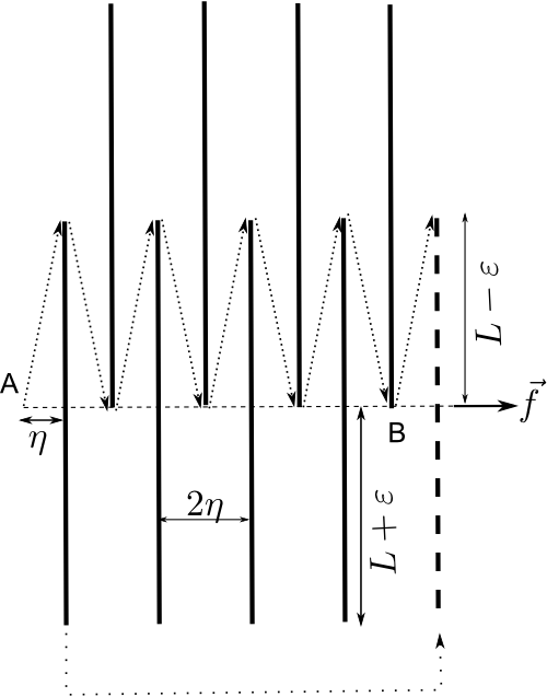
To start with, we show that spacing and size are really important. Let the robot face straight line segments of length perpendicular to ; see Fig. 1(b), where . They are separated by the space and slowly drift in the direction of with the speed . The odd segments are vertically aligned, the even segments are shifted upwards by , where . Initially the robot is in the location . The upper dotted line illustrates the path of the robot driven by the proposed control law.
To reach point B, the robot spends no less than time units. For this time, B moves a distance and reaches a location to the left of if . So for any speed excess ratio , there exist so tight spacing and large obstacle size that the overall drift of the robot is contrary to the desired direction. What is worse, that time is enough for the first segment to arrive at the dashed position over the lower dotted path if , which can ensured for any by picking and . So if every segment performs such rearrangement just after the robot bypasses it, the overall drift of the robot contrary to will be never terminated.
Thus apart from the speed ratio, criteria for achieving of the control objective should somehow impose requirements on the obstacles sizes and spacing between them.
5.2 Main Results
To flesh out this, we introduce geometric objects, called hats. Being the parts of the plane that should be free from the obstacles, they characterize the required inter-obstacle spacing. These objects depend on an angle , which will depend on the speed ratio in the results to follow.
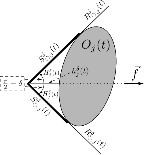
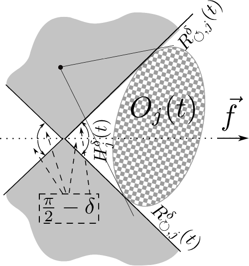
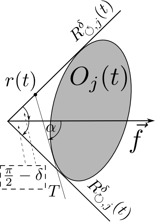
Consider the angle made of two rays that are obtained from the ray spanned by via the counter clockwise and clockwise rotation, respectively, though the angle . Let us translate this angle into the unique position in the plane where its both rays and are tangential to the boundary of ; see Fig. 2(a). The -hat of the th obstacle at time is the part of the plane bounded by
-
1)
the segment of between the vertex of and the furthest point of ;
-
2)
the segment of between the vertex of and the furthest point of ;
-
3)
the least part of the boundary that connects these segments and is closer to the angle vertex.
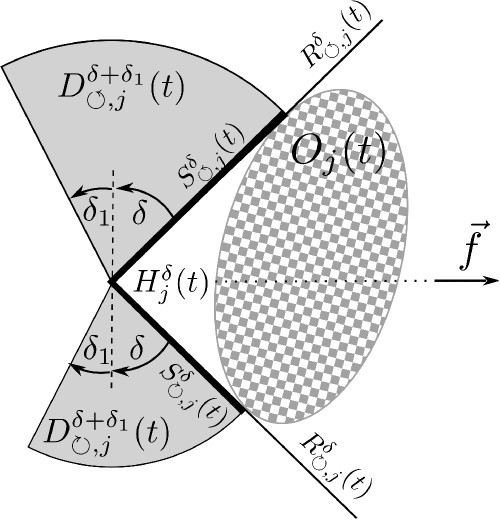
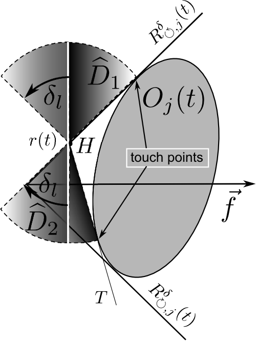
The height of this hat is the distance from the vertex of to the obstacle. The -extended -hat is the union of with the following two sets (see Fig. 2(b)):
-
•
the sector swept by the segment when counter-clockwise rotating through the angle ;
-
•
the sector swept by the segment when clockwise rotating through the angle .
Theorem 5.1
Suppose that the ‘two-sided’extension of (6)
| (8) |
holds, the obstacles are always convex and do not collide with each other, and for ,
-
a)
the -extended -hat of any obstacle of class is always disjoint with the obstacles of class and
-
b)
for and any , the location of the robot does not lie in the -hat of any obstacle of class .
Moreover let a) and b) be true for a larger value of :
| (9) |
Then the proposed controller drives the robot through the obstacle-free part of the environment. Moreover, it can be tuned so that the robot always drifts in the right direction
| (10) |
Specifically, this is true if in (1) is chosen so that
| (11) |
The proof of this theorem is given in Appendix B.
Remark 2
i) If b) is true for , it also holds for satisfying (9) by d) in Observation B.1. So the concerned assumption of Theorem 5.1 is always valid and is stated only to introduce in (11).
ii) Theorem 5.1 assumes undefined end of the experiment and so extends the conclusion on all the future. It remains true if time is confined to a finite interval in the assumptions and conclusion. Then it suffices to check a) only for since this implies a) with a larger , like in i).
iii) Function satisfying (11) does exist. For example given an estimate of the hat height , it suffices to pick , put for , and extend on as a continuous decaying function. Another option is a constant , which does not need estimation of the hat height.
iv) A guideline given by (11) is to pick close to , which may be used if estimation of is troublesome.
v) As , all hats degenerate into parts of the obstacle boundary. Then a) and b) come to disjointness of the obstacles and , whereas (11) come to .
6 Illustrations of the main results for special scenarios.
These scenarios involve obstacles of special shapes. For each scenario, we start with explicit computation of the concerned hats and related specifications of Theorem 5.1. In some cases, these hats appear to be rather complex. So we finish with easier comprehensible corollaries that result from replacement of the hats with their upper estimates by simple shapes.
6.1 Disk-shaped obstacles
In robotics research, obstacles are often represented by disks. Let the th obstacle be the disk of the constant radius with the center whose velocity is . The ‘collision avoidance’ condition (6) is equivalent to (8) and shapes into
| (12) |
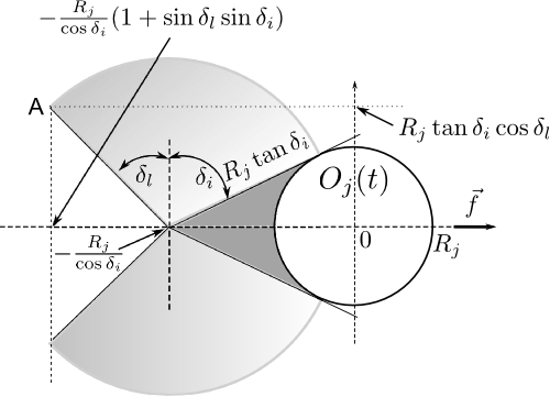
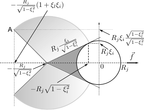
Elementary geometrical considerations show that the -hat of the th obstacle is the set shadowed in dark in Fig. 3(a). The -extended -hat is obtained via union of the hat with two slightly shadowed disk sectors. In the basic case where , Fig. 3(a) shapes into Fig. 3(b), where .
By bringing the pieces together, we arrive at the following.
Proposition 6.1
If (12) and (7) are true, the robot is driven through the obstacle-free part of the environment. Suppose also that for any obstacle , its extended hat from Fig. 3(b) is always disjoint with the obstacles of class , and the robot is initially outside its hat from Fig. 3(b). Moreover let these claims be true for the hats from Fig. 3(a) with some . Then the robot always drifts in the right direction, i.e., (10) is true, if are chosen so that
| (13) |
In (13), can be replaced by any its known upper bound. If this bound is not available, can be picked constant.
Now we apply Proposition 6.1 to more special scenarios and, by sacrificing a part of its content, provide convergence criteria in terms of distances instead of hats.
A scene cluttered with irregularly and unpredictably moving disk-shaped obstacles with a common velocity bound . Let be a time-invariant lower estimate of the spacing between the th and th obstacles. Since -hat is contained by the disk passing through its vertex (see Lemma B.1 below) and the extended hat is contained by the disk centered at the origin and passing through point A in Fig. 3(b), we arrive at the following claim.
Claim 1
The proposed controller guarantees no collisions with the obstacles and constant drift in the right direction if
| (14) |
and the ‘parameter’ of the controller is chosen so that
| (15) |
Here , may be arbitrarily small and is picked so that (14) remains true with replaced by .
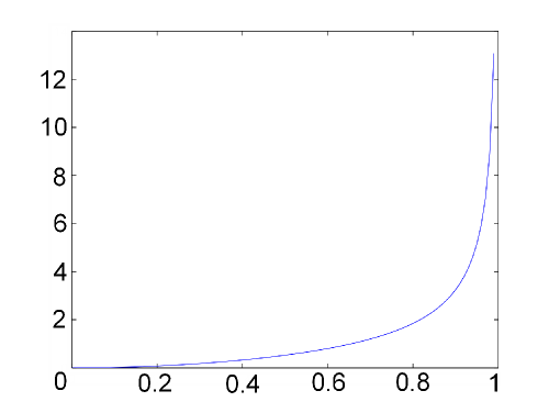
0 1/8 1/7 1/6 0 3% 4% 6% 1/4 1/3 1/2 12% 22% 52% 124%
It follows that if the robot is four times faster than the obstacles, the spacing between them should exceed nearly negligible 6% of the obstacle diametersize. If the robot is twice faster, this percentage increases to the quarter of the size. By Fig. 5, the requirements to the initial location of the robot are even more liberal.
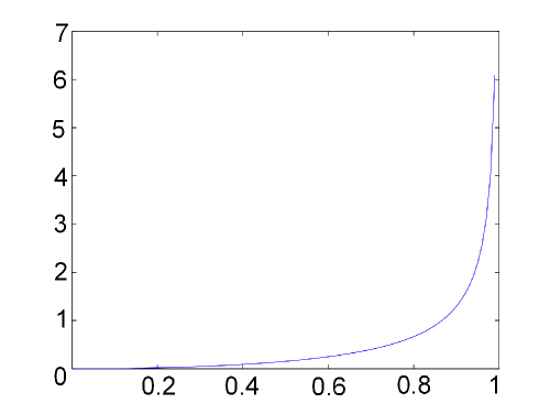
0 1/8 1/7 1/6 0 0.8% 1% 1.4% 1/4 1/3 1/2 3% 6% 15% 41%
Motion along a corridor obstructed with irregularly and unpredictably moving disk-shaped obstacles with a common velocity bound ; see Fig. 6(a).
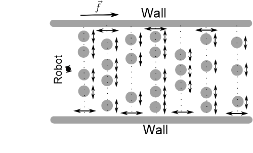

For simplicity only, we assume obstacles with a common radius . They are partitioned in groups so that the disk centers are always ‘vertically’(in Fig. 6(a)) aligned within any group. A group may be ‘horizontally’displaced but its ‘horizontal’projection does not leave a steady interval, disjoint with the intervals of other groups. The walls of corridor are cigar-shaped obstacles (rectangles smoothly concatenated with two end-disks of proper radii) parallel to . The obstacles move without collisions. Initially the robot is inside the ‘rectangular’part of the corridor, to the left of all intervals, and in touch with no obstacle. The velocity ratio , which guarantees collision avoidance by Theorem 4.1.
Starting with the case of one group, we are interested in the velocity ratio for which
p) the robot driven by the properly tuned controller does pass the corridor in the right direction, no matter how small the minimal ‘vertical’spacing between the obstacles is.
Since the hats of the walls lie to the left of their rectangular parts, a) and b) in Theorem 5.1 are fulfilled for walls. For the disks, a) is true if the extended hat from Fig. 3(b) lies in the horizontal strip spanned by the disk. This holds iff , i.e., the robot should be 41% faster than the obstacles. Then p) holds provided that initially the robot is at a distance from the leftmost interval. This extends on many groups if the distance between the th and th intervals exceeds for any i. We remark that controller tuning depends only on and : it suffices that , where is chosen so that .
6.2 Thin cigar-shaped obstacles
Cigar is the body obtained by smooth concatenation of a rectangle with two end-disks of proper radii; see Fig. 7(a).
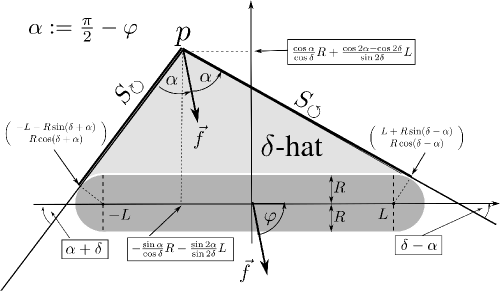

Let stand for the angle from the desired direction to the cigar centerline. If or , the -hat and extended hat of the cigar are identical to those of the respective end-disk; see Figs. 7(b) and 3. For , the -hat can be found via elementary geometrical considerations and is shown in Fig. 7(a) in lighter dark. The -extended -hat is obtained by adding the disk sectors swept by the segments and from Fig. 7(a) when rotating counter clockwise and clockwise, respectively, around the hat’s vertex through the angle . If , the picture is symmetric.
To simplify formulas, we confine ourselves to asymptotic analysis as and consider thin cigars with , called segments. The subsequent characterization of segment hats is true with as high precision as desired and the final claims are valid if is small enough. Transition to ‘non-asymptotic’exact claims results from elementary substitution of the true hats in place of their asymptotic counterparts.
For , the hats of the segment are depicted in Fig. 8 and obtained via elementary geometrical considerations; the extended hat is composed of the hat and two slightly shadowed disk sectors.
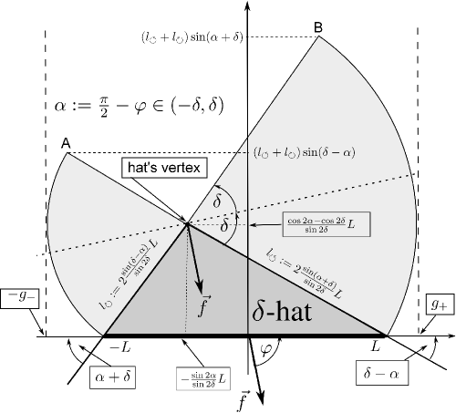
For , the picture is symmetric. For the other , the hats are empty.
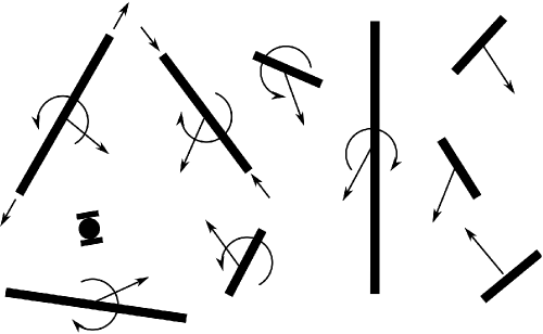
Now we consider a scene cluttered with moving disjoint segments; see Fig. 9(a). The th of them has time-varying half-length and rotates with the angular velocity ; the velocity of its center is . For the sake of brevity, we assume common bounds for the parameters of all segments:
and consider controller with only one class: .
Proposition 6.2
Let the robot be faster than the obstacles:
| (16) |
If the ‘parameter’ of the controller is chosen so that , no collision with the obstacles occurs. Suppose also that the -extended -hat of any segment (see Fig. 8) is always disjoint with the other segments, and the robot is initially outside their -hats. Moreover let these be true for some . Then the controller can be tuned so that the robot always drifts in the right direction, i.e., (10) is true. For this to hold, it suffices to pick so that
| (17) |
Now we apply this proposition to more special scenarios and, by sacrificing a part of its content, provide convergence criteria in terms that are simpler than hats.
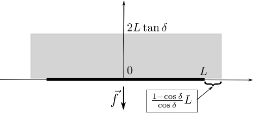
Steady-size segments irregularly and unpredictably moving so that they remain perpendicular to the desired direction . The directions of their velocities and so the paths of the centers are not anyhow restricted. In this case, and (16) shapes into . It is easy to see that the -extended -hat is contained in the rectangle from Fig. 9(b), where and for . Let the spacing between any two obstacles be always no less than a constant in the direction of and no less than in the perpendicular direction. Then we arrive at the following.
Claim 2
The proposed controller guarantees obstacle avoidance and constant drift in the right direction (10) if there is enough space between the obstacles , the initial distance from the robot to any of them is no less than , and is chosen so that Here may be arbitrarily small and is picked so that .
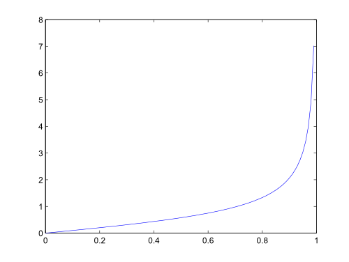
0 1/8 1/7 1/6 0 13% 14% 17% 1/4 1/3 1/2 26% 35% 58% 100%
The function is illustrated in Fig. 10. For example, if the robot is at least eight times faster than the obstacles, spacing between them in the direction of should exceed only 13% of the obstacle length for the controller to succeed. If the robot is twice faster, this percentage increases to 58% of the length. As follows from Fig. 11, the requirements to spacing in the perpendicular direction are much more liberal.
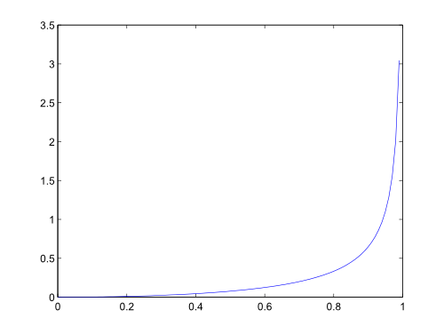
0 1/8 1/7 1/6 0 0.4% 0.5% 0.7% 1/4 1/3 1/2 1.5% 3% 8% 20%
It is instructive to compare the last claims with the counterexample from subsect. 5.1.
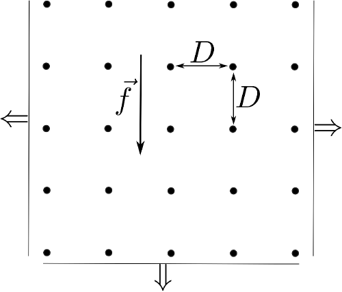

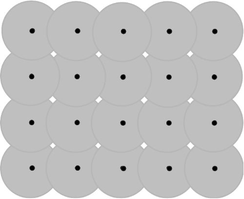
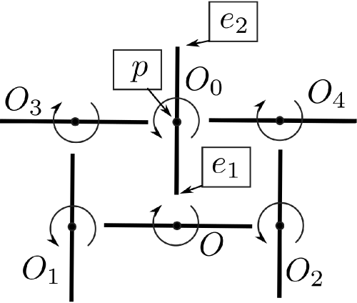
Navigation in the field of rotating segments. We consider an infinite Cartesian -grid in the plane; see Fig. 12(a). It is not limited along the abscissa axis and in the negative direction of the ordinate axis, which is identical to the desired direction . At the same time, the grid has the ‘upper’row.
Every vertex of the grid is a pivot point for a segment with length ; see Fig. 12(b). The segments rotate about their centers with the common angular speed in the directions and from initial orientations shown in Fig. 12(b). Such motion of the ensemble is possible if the segments at the ends of the cell’s diagonal do not collide, which is equivalent to . To make the things interesting, the focus is on the case where the paths of the segments overlap , with the path being the disk swept by the segment. So the ‘path-free’part of the plane is composed of infinitely many compact disconnected areas, shown in Fig. 13(a) in white. Hence motion through this part with constant drift in the direction of is not feasible. Initially the robot is in touch with no segment and above the upper row of the grid.
We assume that the robot is able to overtake any obstacle point . Then by Theorem 4.1, the proposed controller ensures collision avoidance if .
Claim 3
The proof of this claim is given in Appendix C.
If , (18) and , i.e., the robot should be faster than the obstacles for the constant drift in the right direction.
The right-hand side of the first inequality from (18) treated as a function of is illustrated in Fig. 14.
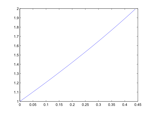
0 1/8 1/7 function 1 26% 30% 1/6 1/4 1/3 function 35% 53% 73%
Since (excess ), that inequality is fulfilled for robots that are at least times faster than the obstacles. For them, the controller ensures constant drift in the right direction irrespective of how small the white cells in Fig. 13(a) are. For slower robots, the ratio should exceed the minimum as is shown in Fig. 14(b).
7 Simulations
For the velocity controlled vehicle, the control was updated at a period of , and 40 rays in Fig. 1(a) were used to detect obstacles. Their edges were associated with the difference in two sequentially detected distances. Following a given azimuth was modeled as reaching a faraway target point. The function in (2) was common for all obstacles and specified as a continuous piecewise linear function, whose fractures are shown in Table 1
| (m) | 0 | 0.5 | 1.0 | 1.5 | 2.0 | 2.5 | 3.0 | 100.0 |
|---|---|---|---|---|---|---|---|---|
| (rad) | 1.52 | 1.27 | 1.21 | 0.43 | 0.2 | 0.02 | 0.01 | 0.003 |
They result from optimization by a genetic algorithm (MATLAB 2013a, Optimization Toolbox v6.3), minimizing the time of target reaching while respecting the safety margin to the obstacles in the scenario from Fig. 16.
In the simulation from Fig. 16, the robot efficiently converges to the target in a complex scene with many translating and rotating obstacles. In the simulation from Fig. 17, the mission was troubled by vehicle dynamics and noise. Unicycle dynamics were used with the turning rate limit of . A random Gaussian disturbance with the standard deviation of was added to the control input. These entailed no problems for the method, displaying a promising potential to cope with noise and dynamic constraints.
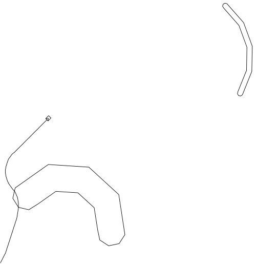
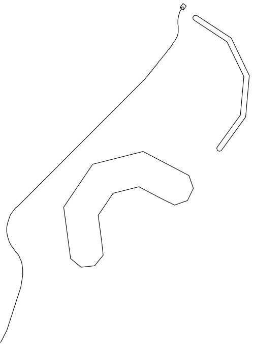
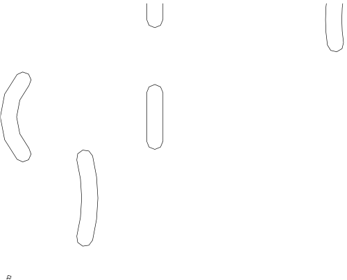
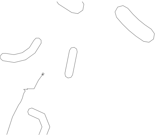
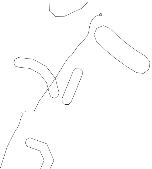
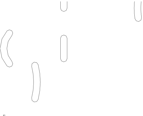
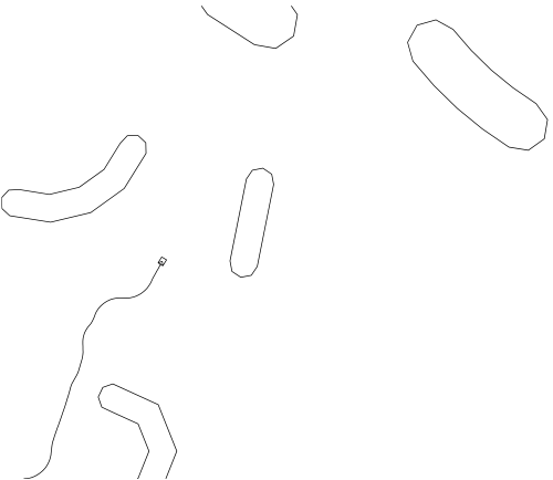
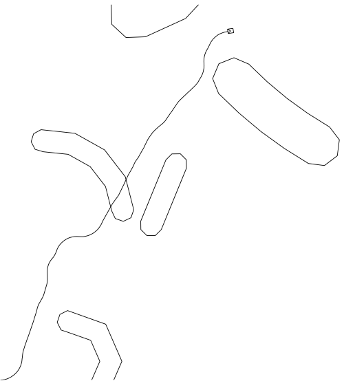
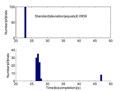
In the scenario from Fig. 16, the proposed control law (PCL) was compared with the popular Velocity Obstacle method (VOM). The latter was given advantage over PCL by access to the obstacle full velocity and knowledge of its future movement within the next . VOM also took into account the desired offset from the obstacle and a weighted cost to compromise progression to the target and separation from obstacles. These parameters were optimized, like for PCL. A Gaussian noise with the standard deviation of was added to the heading direction. The performance measure was the time taken to reach the target. By Fig. 18, PCL on average outperforms VOM: VOM took a longer (occasionally, a much longer) path around the obstacles.
8 Summary
In this paper, a method for guidance of a Dubins-like vehicle towards a target in an environment with moving obstacles is considered. The vehicle is provided with the relative bearing angle of the target, and the distance to the nearest point of the obstacle set if it is within the given sensor range. The proposed control law is composed by biologically inspired reflex-level rules. Mathematically rigorous analysis of this law is provided; its convergence and performance are confirmed by computer simulations.
References
- [1] J. Canny. The Complexity of Robot Motion Planning. MIT Press, Cambridge, MA, 1988.
- [2] A. Chakravarthy and D. Ghose. Obstacle avoidance in a dynamic environment: a collision cone approach. IEEE Transactions on Systems, Man, and Cybernetics, 28(5):562–574, 1998.
- [3] F.H. Clarke. Optimization and Nonsmooth Analysis. Wiley, NY, 1983.
- [4] M. Erdmann and T. Lozano-Perez. On multiple moving objects. Algorithmica, 2(4):477 –521, 1987.
- [5] A.F. Filippov. Differential Equations with Discontinuous Righthand Sides. Kluwer Academic Publishers, Dordrecht, the Netherlands, 1988.
- [6] P. Fiorini and Z. Shiller. Motion planning in dynamic environments using velocity obstacles. International Journal of Robotics Research, 17(7):760–772, July 1998.
- [7] D. Fox, W. Burgard, and S. Thrun. The dynamic window approach to collision avoidance. IEEE Robotics and Automation Magazine, 4:23 – 33, 1997.
- [8] T. Fraichard. Trajectory planning in a dynamic workspace: a state-time space approach. Adv. Robotics, 13(1):75–94, 1999.
- [9] T. Fraichard and H. Asama. Inevitable collision states. a step towards safer robots? In IEEE International Conference on Intelligent Robots and Systems, pages 388 – 393, 2003.
- [10] E. Frazzoli, M. Dahleh, and E. Feron. Real-time motion planning for agile autonomous vehicles. Journal of Guidance, Control, and Dynamics, 25(1):116 –129, 2002.
- [11] M. Hoy, A. S. Matveev, and A. V. Savkin. Collision free cooperative navigation of multiple wheeled robots in unknown cluttered environments. Robotics and Autonomous Systems, 60(10):1253–1266, 2012.
- [12] D. Hsu, R. Kindel, J.-C. Latombe, and S. Rock. Randomized kinodynamic motion planning with moving obstacles. The International Journal of Robotics Research, 21(3):233–255, 2002.
- [13] R. Kulić and Z. Vukić. Methodology of concept control synthesis to avoid unmoving and moving obstacles. J. Intell. Robot Syst., 45:267 –294, 2006.
- [14] L. Lapierre, R. Zapata, and P. Lepinay. Combined path-following and obstacle avoidance control of a wheeled robot. The International Journal of Robotics Research, 26(4):361–375, 2007.
- [15] F. Large, C. Lauger, and Z. Shiller. Navigation among moving obstacles using the NLVO: Principles and applications to intelligent vehicles. Autonomous Robots, 19:159 –171, 2005.
- [16] J.C. Latombe. Robot Motion Planning. Kluwer Academic Publishers, London, 1991.
- [17] S. LaValle. Planning Algorithms. Cambridge University Press, Cambridge, NY, 2006.
- [18] A.S. Matveev, M.C. Hoy, and A.V. Savkin. A method for reactive navigation of nonholonomic under-actuated robots in maze-like environments. Automatica, 49(5):1268–1274, 2013.
- [19] A.S. Matveev, H. Teimoori, and A.V. Savkin. A method for guidance and control of an autonomous vehicle in problems of border patrolling and obstacle avoidance. Automatica, 47:515–524, 2011.
- [20] A.S. Matveev, C. Wang, and A.V Savkin. Real-time navigation of mobile robots in problems of border patrolling and avoiding collisions with moving and deforming obstacles. Robotics and Autonomous Systems, 60(6):769–788, 2012.
- [21] Y.K. Nak and R. Simmons. The lane-curvature method for local obstacle avoidance. In IEEE International Conference on Robotics and Automation, pages 1615 – 1621, November 1998.
- [22] E. Owen and L. Montano. A robocentric motion planner for dynamic environments using the velocity space. In IEEE International Conference on Intelligent Robots and Systems, pages 2833 – 2838, 2006.
- [23] Zh. Qu, J. Wang, and C.E. Plaisted. A new analytical solution to mobile robot trajectory generation in the presence of moving obstacles. IEEE Transactions on Robotics, 20(6):978–993, 2004.
- [24] J. Reif and M. Sharir. Motion planning in the presence of moving obstacles. J. ACM, 41:764 –790, 1994.
- [25] A. V. Savkin and M. Hoy. Reactive and the shortest path navigation of a wheeled mobile robot in cluttered environments. Robotica, 31(2):323–330, 2013.
- [26] A. V. Savkin and C. Wang. A simple biologically inspired algorithm for collision-free navigation of a unicycle-like robot in dynamic environments with moving obstacles. Robotica, 31(6):993–1001, 2013.
- [27] M. Seder, K. Macek, and I. Petrovic. An integrated approach to realtime mobile robot control in partially known indoor environments. In 31st Annual Conference of the IEEE Industrial Electronics Society, pages 1785 – 1790, November 2005.
- [28] R. Simmons. The curvature-velocity method for local obstacle avoidance. In IEEE International Conference on Robotics and Automation, pages 3375 – 3382, November 1996.
- [29] J. A. M. Spencer. Continuum Mechanics. Dover Publications, NY, 2004.
- [30] H. Teimoori and A. V. Savkin. A biologically inspired method for robot navigation in a cluttered environment. Robotica, 28(5):637–648, 2010.
- [31] H. Teimoori and A. V. Savkin. Equiangular navigation and guidance of a wheeled mobile robot based on range-only measurements. Robotics and Autonomous Systems, 58(2):203–215, February 2010.
- [32] A. Wu and J.P. How. Guaranteed infinite horizon avoidance of unpredictable, dynamically constrained obstacles. Autonomous Robots, 32:227 –242, 2012.
Appendix A Proofs of Lemma 4.1 and Theorem 4.1
PROOF OF LEMMA 4.1. Suppose to the contrary that for some and . By continuity, there exist and such that
Let the robot start at time on the outer normal , where is so small that and . By Definition 1, there exists an admissible velocity profile under which
| (19) |
Let be the point of closest to . By Lemma A.1 [20] for and ,
At the same time according to (A.1) in [20],
This and (19) yield , though can be chosen as close to as desired. This contradiction proves the lemma.
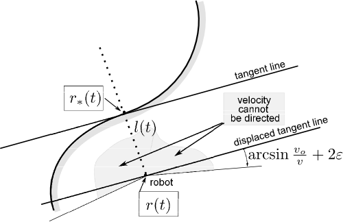
PROOF OF THEOREM 4.1. Suppose the contrary: . Since is open in , its leftmost connected component has the form , where for some . Let be the point of closest to for , and . For , we introduce (see Fig. 19(a)) the point that is counter-clockwise/clockwise ahead of and separated by along the boundary , the polar angle of in the robot’s frame and the angle from to , the angle from to , the angle from to , and the angle from to .
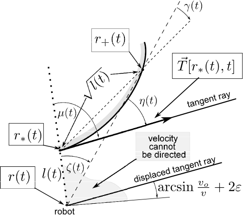
Here and as since the vector is tangent and as . Thus . By (7), there exist such that , where . Now we focus on so close to that and , which implies in (2).
The robot’s view in the directions is obstructed by . Hence is covered by the range of the extended facet . The respective part of cannot be shadowed by other obstacles for . Indeed as , the locus of ‘shadowing’points collapses into a part of and so the distance from the locus to the other obstacles is lower limited by a non-zero value since the obstacles do not collide. Hence for the polar angle of the robot’s velocity , we have . By replacing in the foregoing, we see that .
Overall, is not directed to the shadowed sector from Fig. 19(b), i.e., the angle subtended by the velocity and the unit inner normal is no less than . So the related normal component of
At the same time according to (A.1) in [20],
in violation of and as . The contradiction obtained completes the proof.
Appendix B Proof of Theorem 5.1
We start with a deeper insight into the -hats of convex bodies, where . We fix and , focus on , assume the polar angle of to be zero, and add the adjective free to signal that the facet is calculated in the absence of the other obstacles.
Let be a natural parametric representation of the boundary , where is the arc length and is to the left as ascends, and be the unit normal to directed inwards . The ray is the locus of points from which the uppue/lower edge of the free visible facet of is given by . By the Frenet-Serrat equations , where the signed curvature since is convex. Hence as ascends, the ray (nonstrictly) displaces to the left with respect to its current position observed from the ray origin. By the same argument, rotates counter-clockwise, and makes one full turn as runs the entire perimeter of . As a result, we arrive at the following.
Observation B.1
a) Let and be values of for which
the polar angle of equals and , respectively. The locus of points whose view in the direction of is obstructed by
the free -facet of is bounded by ,
, and the respective part of
(see Fig. 20(a)).
b) Let be the largest/smallest value of for
which , respectively. The -hat
of is bounded by ,
, and the least part of that
connects these rays and excludes from the hat.
c) if .
d) as , and the ends of
the segments from Fig. 2 converge
to the respective ends of
uniformly over .
Corollary 1
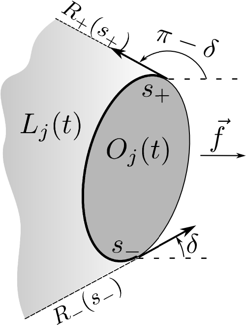
The interiors of the sectors shadowed in Fig. 20(b) do not contain points for which the obstacle edges have equal angular discrepancy with respect to .
This holds by c) in Observation B.1 since such points are vertices of hats. Exactly at these points the control law is discontinuous at time if the effect of the other obstacles can be neglected.
Lemma B.1
The maximal distance from a point of the hat to equals the height of the hat.
Proof: Since is convex, so is the distance function . Hence its maximum over the triangle spanned by the vertex of the angle and the points from 1) and 2) on page 5.2 is attained a vertex , which is . It remains to note that this maximum equals that over the hat.
The ray evidently moves without rotation. Its normal velocity is that with respect to itself; with the positive direction being to the left when observing from the ray origin.
Lemma B.2
Putting , we have for
Proof: Let and be the natural parametric representation of the reference configuration boundary . We put , etc. There are such that . Let be the positively oriented unit vector normal to . The line
contains and so . By Corollary 2 in [3, Sect. 2.8] combined with Definition 2.3.4 and Proposition 2.1.2 [3], the one-sided derivatives on the right do exist and
where ranges over all probability measures on . So this are equal to of the integrand
where (a) holds since . This completes the proof. The case is considered likewise.
Now we start to examine the robot driven by the proposed control law. The -facet of the obstacle is given by (2) and (3), where is replaced by everywhere.
Lemma B.3
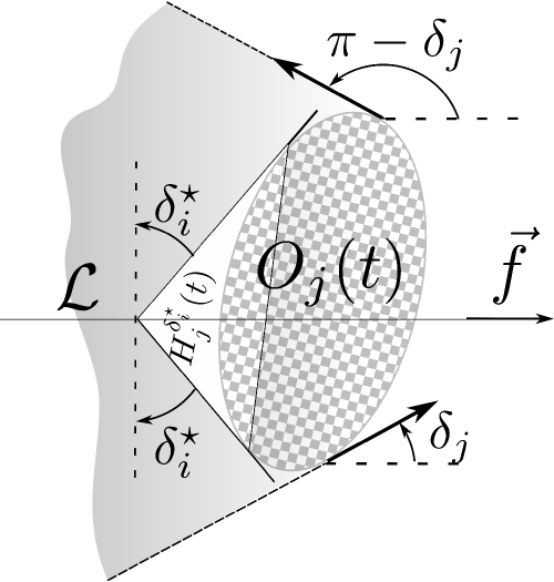
a) If the robot is on , the normal component of its relative velocity with respect to each of the rays is no less than , where . b) If the robot is on , the above normal component does not exceed .
Proof: We focus on (a), (b) is proved likewise. Since and is convex, obstructs the view in the direction of , lies in the angle subtended by and the tangent ray from Fig. 20(c), and its free facet has the form . So , whereas since does not exceed radian. By (1), (2) (11) and Lemma B.1, the range of the free extended facet does not cover the circle since its angular span thanks to . So by (11), the robot’s absolute velocity has the polar angle unless a sector from Fig. 21(a) is partly shadowed by an extended facet of another obstacle . Now we show that this does not hold.
Suppose the contrary. Then obstacle (of class ) contains a point whose rotation through an angle about goes through and ends on . The locus of such points lies in the union of the domain from Fig. 21(b) and two larger sectors and that are obtained from and , respectively, by extra rotation of the radius through angle . However by (11), this union is a subset of the -extended -hat of . Thus intersects this hat, in violation of a) in Theorem 5.1. Hence has the polar angle indeed.
So subtends the angle with the ray and the angle with . So the normal components of are and , where and so no less than in both cases. It remains to note that both rays are translated at the speed by (8) and Lemma B.2.
Corollary 2
The robot is always outside the -hats of all obstacles of class .
PROOF OF THEOREM 5.1: If at time the ray emitted from the robot in the direction of hits no extended facet, the robot’s velocity and so (10) does hold with . Suppose that hits an extended facet; let be the index of the first of them and be defined from (2). By Corollary 2, the robot is not in the -hat of the th obstacle. So in view of a) in Observation B.1, the robot is located in the shadowed domain from Fig. 21(c).
Let the robot is above the line from Fig. 21(c). Let be the polar angle of the upper edge of the free facet of . Then , where is the upper end of the extended facet. Since due to (11), its deviation from the angle of does not exceed . So were the robot’s velocity directed to that upper end, the angle between and would be acute . That direction can be dismissed by either the lower edge of the same obstacle or by another obstacle. However this may result only in decrease of . Thus in any case, and so
i.e., (10) does hold with . The case where the robot is below is considered likewise.
Appendix C Proof of Claim 3
Since the right-hand side of the second inequality from (18) estimates the height of the -hat from above by Fig. 8, the robot is initially outside the -hats of all horizontal segments. The same is true for the vertical segments since their hats are empty.
It remains to check that the extended hat of any obstacle is always disjoint with the other obstacles. In doing so, it suffices to examine only five neighbors of (see Fig. 13(b)) for since otherwise the hat is empty.
The -extended -hat is disjoint with if in Fig. 8, the ends of lie above the lines spanned by the segments of the lengths and . Analytically this means that
Here are the coordinates of in the local frame of (see Fig. 8). Via elementary triginometrical identities, these inequalities are shaped into
This is true by (18) since does not exceed .
We focus on , is considered likewise. The pivot of has the coordinates ; the unit vector normal to is . So the line spanned by is given by . The -extended -hat from Fig. 8 is disjoint with if the distance from the vertex of the -hat from Fig. 8 to exceeds the radius of the left shadowed disk segment. With regard to the coordinates of given in Fig. 8, this means that for all ,
By elementary calculus, and so , which shapes the condition into
The difference between the expression on the right and the right-hand side of the first inequality from (18) equals
Thus is disjoint with the -extended -hat if (18) holds.
We focus on . Since is always parallel to , it suffices to show that the relative ordinate of its pivot exceeds those of A and B in Fig. 8:
for all . Only can be examined since for them, keeps the inequality true. Then it shapes into
Since the left-and right-hand sides descend and ascend, respectively, as grows, the condition is equivalent to
The numerator of the second ratio decays on the interval ; its value at the right end by and elementary estimation. So this ratio is positive. Thus the inequality holds by (18) and is disjoint with the -extended -hat of . For , the conclusion is the same.