Topological Phases in the Single-Layer FeSe
A distinct electronic structure was observed in the single-layer FeSe which shows surprising high temperature superconductivity over 65k. Here we demonstrate that the electronic structure can be explained by the strain effect due to substrates. More importantly, we find that this electronic structure can be tuned into robust topological phases from a topologically trivial metallic phase by the spin-orbital interaction and couplings to substrates. The topological phase is robust against any perturbations that preserve the time-reversal symmetry. Our studies suggest that topological phases and topologically related properties such as Majorana Fermions can be realized in iron-based high Tc superconductors.
The single-layer (SL) FeSe filmWang2012-fese ; Liu2012-fese ; He2013-fese ; Tan2013-fese ; Peng2014-fese ; Zhang2014-fese ; Lee2014-fese that is epitaxially grown on SrTiO3(001) surface exhibits several remarkable unique features compared with the bulk FeSeHsu2008-fese ; Yeh2008-fese and other Fe-based superconductorsJohnston2010-review ; Dagotto2013-review . In the bulk FeSe, the superconducting transition temperature, 8KHsu2008-fese , and the electronic structure is characterized by the presence of both hole pockets around point and electron pockets around M point in the first Brillouin zone[BZ]Subedi2008-dft ; Richard2011-review . In the SL FeSe, exceeding 65K was observedWang2012-fese . Furthermore, there are only electron pockets around M point and the hole pockets at point are absentLiu2012-fese ; He2013-fese ; Tan2013-fese . The ARPES experimentsLiu2012-fese ; He2013-fese have shown that the electronic structure of the SL FeSe cannot be obtained through the directly rigid band shifting because a new band gap below Fermi surface is developed at M point. The origin of the novel electronic structure and its relation to the high in the SL FeSe remain as open issues.
Here we first discuss the origin of the novel band structure as a result of the lattice mismatch between the FeSe and substrate SrTiO3. We demonstrate that the lattice distortion can induce a phase transition around M point from a gapless phase to a gaped phase and simultaneously suppress the hole-like band at point.
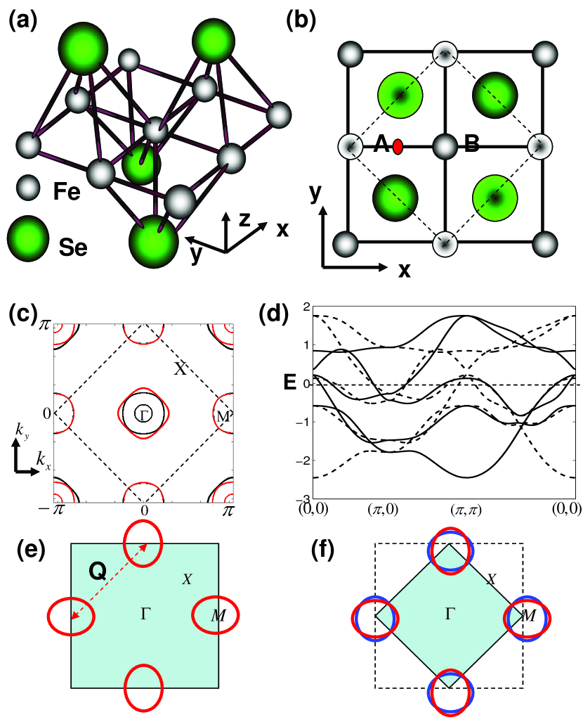
It is known that the electronic structure in the bulk FeSe is rather two-dimensional and is determined by the single FeSe tri-layer structure as shown in Fig. 1(a) and (b) in which the unit cell includes two Fe labeled as and and two Se. The band structure calculations from the density functional theory show that only the five 3d orbitals of Fe play the significant roles near Fermi surfacesSubedi2008-dft . A general effective d-orbitals model for the band structure in the real space can be written as
| (1) |
Here, label two different Fe A and B. labels spin. label five d orbitals: (, , , , ). label lattice sites. is the corresponding hopping parameters. is the on-site energy of d orbital. creates an spin- electron in th orbital of Fe at site . In the momentum space, the Hamiltonian can be written as
| (2) |
Here, is defined in the BZ of one Fe unit cell, and with . . has been widely utilized to describe the electronic structure of all kinds of iron-based superconductorsKuroki2008-prl ; Graser2009-njp . The difference between the one Fe unit cell and two Fe unit cell pictures can be found in section I of supplementary materials.
The Fermi surface and band structure along high-symmetry lines are shown in Fig. 1(c) and (d). In Fig. 1(c), there are three hole pockets around the point and the two electron pockets around point. We have specified that the black pockets in Fig.1(c) are from while the red pockets from . In Fig. 1(d), the solid or dashed lines denote the bands from or .
In Fig. 1, there is no gap openning in the band structure at M point. To gain the insight of the gap openning observed experimentally in the SL FeSe, we analyze the symmetry characters of the bands. As shown in Fig. 1, there are four bands along -M direction near Fermi surfaces. Each and contribute two bands. The bands contributed from and have opposite parityHu2013-odd ; Hu2012-s4 . The two bands from belong to and representationsCvetkovic2013-band , which is the reason why the two bands can cross each other without showing the sign of hybridization. However, the two bands from belong to the same representationsCvetkovic2013-band . If these two bands across each other, the hybridization must take place. We notice that these two bands are attributed to the and orbitals respectively near M point. Moreover, the symmetry characters of the bands do not depend on the inter-orbital couplings because the couplings between two different d-orbitals at high symmetry points, such as and , vanish. Therefore, we can adjust the relative energy difference between and at M points to create an crossing between the two bands. such an crossing can result in a gap openning at M point because of the hybridization.
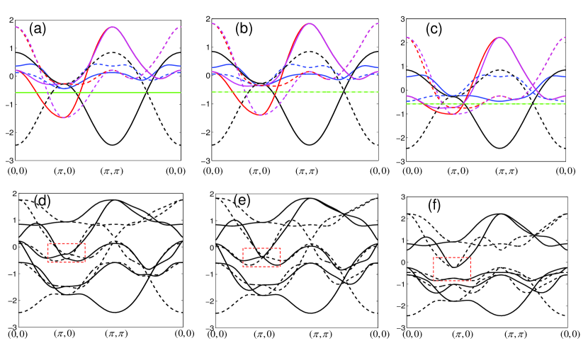
To confirm above symmetric analysis, we present an evolution of the band structure by manipulating hopping parameters in Fig.2. The bulk band structures are shown in Fig.2 (a) and (d). Note that we set all inter-orbital hoppings zero in Fig.2 (a) in order to clearly distinguish the five -orbital bands. In Fig. 2 (a), the red-dashed band and the blue-dashed band has no cross along (0,0)-() line. In Fig. 2 (d), there is no band gap opening around M point, i.e., ()( see the red rectangle region in Fig. 2(d)). When we adjust the values of some hopping parameters (See the caption of Fig. 2), the red-dashed band is pushed down and the blue-dashed band is pushed up. The critical case is shown in Fig. 2 (b), the two bands meet each other at point. Then, the continued push leads to the cross between red-dashed and blue-dashed bands at some point between (0,0) and () (See Fig. 2 (c)). Turning on the inter-orbital hoppings, we obtain a new band structure shown in Fig. 2 (f). Compared with the bulk bands in Fig. 2(d), the bands in Fig. 2(f) present some new feature, such as (1) the hole pockets around point are pushed down the fermi energy with only electron pockets around point surviving. (2) the band top of hole pockets nearly has same energy as the band bottom of electron pockets. (3) there is a band gap opened at point (See the red rectangle region Fig. 2 (f)). These features of band structure shown in Fig. 2 (f) are comparable to the ARPES observationsLiu2012-fese ; He2013-fese .
From Fig. 2, we can find that the evolution of band structure from bulk FeSe to a SL FeSe is strongly sensitive to the change of a single hopping parameter , i.e., the amplitude of intra- hopping along directions. Namely, the nearest-neighbor intra-orbital hoppings for and changes from the strong anisotropy in the bulk FeSe to near isotropy in the SL FeSe. (See the Fig.7 in supplementary materials). We argue that this is the essential reason to drive the electronic structure of the SL FeSe. The SL FeSe film is epitaxially grown on SrTiO3(001) surface. Consequently, the lattice constant for the SL FeSe film should match the lattice constant for SrTiO3, i.e., 3.905Å. Compared with the bulk FeSe with lattice constant 3.76ÅHsu2008-fese , the apparent lattice mismatch between FeSe and SrTiO3 should exert a strong tensile strain on the FeSe film, and drive the lattice distortion for the FeSe filmTan2013-fese ; Peng2014-fese . The lattice distortion naturally induces the changes of hopping. The influence of lattice distortion to the hopping parameters is discussed in details in the section II of supplementary materials.
After obtaining the new band structure, we can ask whether the new band gap at point (See the red rectangle region Fig. 2 (f)) is topologically trivial or nontrivial when the spin-orbital coupling (SOC) is considered? As the orbitals are significant near Fermi surface, we can write SOC within the subset. Up to the next nearest neighbor, the general SOC Hamiltonian in momentum space can be written as
| (3) | ||||
| (4) | ||||
| (5) |
Here, for spin or . . . The index in the indicate the onsite, nearest neighbor, and next nearest neighbor SOC respectively. describes the SOC between and orbitals. This term does not flip spin and also conserves momentum with respect to the 1-Fe unit cell. describes the SOC between and . This term flips spin and does not conserve momentum with respect to the 1-Fe unit cell. Therefore, essentially break the non-symmorphic lattice symmetry in the SL FeSe, namely, an one-unit translation along the Fe-Fe direction followed by a mirror reflection with respect to the layerLee2008-iron . In the presence of , the 2-Fe unit cell can not be reduction to the 1-Fe unit cell.
The is not the only term that breaks the reduction to the 1-Fe unit cell. If we consider the effect of a substrate, the space inversion symmetry is naturally broken for the SL FeSe. Such a parity breaking can also result in a term that only preserves the 2-Fe unit cellHu2013-odd ,
| (6) |
Here, measures this parity breaking effect. Likewise, we only focus on three orbitals. If we take a constant , the term describes a staggered potential in the iron square lattice.
The full Hamiltonian for the electronic structure of the SL FeSe with a substrate is a combination of , and , namely,
| (7) |
The last two terms in only preserve the translational symmetry with respect to the 2-Fe unit cell.
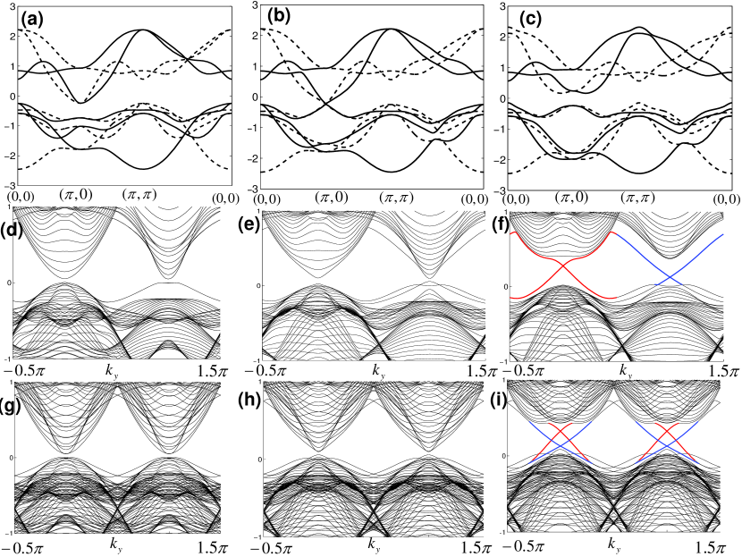
We first concentrate on the effect of which preserves the 1-Fe unit cell. Namely, we ignore both and . The glancing features can be spied through the numerical results of the band structure of the Hamiltonian . The results are shown in Fig. 3. In Fig. 3 (a)-(c), it is explicitly shown that the band gap undergoes a closing and reopening process at point when and are tuned from zero to some finite values. Such a phenomena is a strong indication of a topological phase transitionKane2005-qsh ; Bernevig2006-ti . Fig. 3 (d)-(i) provide a clear proof of the occurrence of the topological phase transition. The spectra in Fig. 3(d)-(f) and Fig.3 (g)-(i) are plotted within the 1-Fe unit cell and the 2-Fe unit cell respectively. The latter can be obtained through folding the 1-Fe unit cell picture with the folding wave vector . It is clear that the signature of the topological phase, gapless edge states, emerges after the band gap reopens.
We can also construct an effective Hamiltonian to describe the topological transition. The detailed derivation is presented in the section III of supplementary materials. Here, we only briefly summarize the result. We define the new basis for and orbitals according to the eigenstates of azimuthal quantum number and magnetic quantum number i.e. , . Around each point, the band structure can be spanned by with and is described by the effective Hamiltonian,
| (8) |
where,
| (9) |
is a matrix. The matrices are defined as , where the Pauli matrices and span the orbital and spin subspaces. . The non-zero elements are and , in which and .
The above effective Hamiltonian has the same form as those for HgTe quantum wellsBernevig2006-ti . At each point, the band gap of Eq. (9) is measured by a Dirac mass . When the overcomes the trivial band gap measured by , namely, the mass changes its sign from positive to negative, a trivial to nontrivial topological phase transition takes place.
We notice that there are even number (two) nontrivial Dirac cone structures in the Hamiltonian as shown in Fig. 3. This is because that the Hamiltonian preserves the full non-symmorphic lattice symmetry so that the band structure decouples into two independent parts in the view of the 2-Fe unit cell. In the 2-Fe unit cell BZ, there is a nontrivial Dirac cone structure at the BZ zone corner for each part. If we understand this in the 1-Fe unit cell picture, a nontrivial Dirac cone structure exists at each point of the 1-Fe BZ. As each Dirac cone structure results in a pair of edge states in a time reversal invariant topological phaseKane2005-qsh ; Bernevig2006-ti , there are two pairs of edge states in this topological phases as shown in Fig. 3. With even pairs of edge states, the topological phase essentially is unstable. One can imagine that if any perturbations that break non-symmorphic lattice symmetry may lead to a coupling between two pairs of edge states to open a gap on edge states. Therefore, we call this topological phase as the weak topological phaseFu2007-prb .
As we mentioned earlier, in the general Hamiltonian (Eq.7) for the SL FeSe with a substrate, both and break the non-symmorhpic lattice symmetry. Therefore, we have to answer how these two terms affect the weak topological phase. First, we ask the effect of . Indeed, the spin-flip term in causes the couplings between the two Dirac cones to create a gap on the edge states. If we assume that the SOC parameter is small, the gap opened on the edge states is given by . Therefore, in principle, the term in Eq. (5) can be considered as a controlling parameter of the gap. The situation is very similar to a topological crystalline insulatorFu2011-tci ; Hseih2012-ti and the topological phase in a system with a non-symmorphic lattice symmetryLiu2013-ns .
However, if we turn on , the situation is drastically different. Rather than destroying the topological phase, we find amazingly that can stabilize the topological phase and drives the system to a strong topological phase. To understand it, we consider the effective Hamiltonian in Eq.8 describing the weak topological phase. If we add , for , the spectrum becomes where we have set effective long-range for simplicity. We can find that the effect of is to change the Dirac masses at the two M points. The changes, , are different for the Dirac cones at the two different points. Therefore, can create a band inversion only in one Dirac cone but not the other, a case for a strong topological phase with odd number of non-trivial Dirac cones. Thus, the strong topological phase is robust against any non-time-reverse-symmetry broken couplings, including the , as long as the coupling does not close the bulk energy gap.
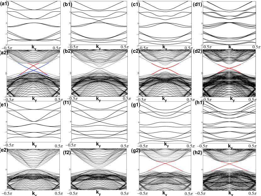
The numerical proof of the above analysis is plotted in Fig. 4 in which the edge spectra in Fig. 4(d2) and (h2) clearly indicate a strong topological phase. More specifically, we discuss the strong topological phases in two cases: (1) and (2) . In the first case, when , one of non-trivial Dirac cones undergoes another gap-close-and-reopen process, and becomes trivial one with positive mass . At each point, only one non-trivial Dirac cone survives. The band evolution for this process is shown in Fig. 4(a1)-(d2). In the second case, when , one of trivial Dirac cones undergoes a gap-close-and-reopen process, and becomes a non-trivial one with negative mass . At each point, only one non-trivial Dirac cone emerges. The band evolution for this process is shown in Fig. 4(e1)-(h2). In the first case, one needs relatively large SOC and the parity broken coupling to overcome the trivial band gap and eliminate one non-trivial Dirac cone. In the second case, we can see that a finite value can create a region of a strong topological phase and can dramatically reduce the critical SOC that is necessary for a topological phase.
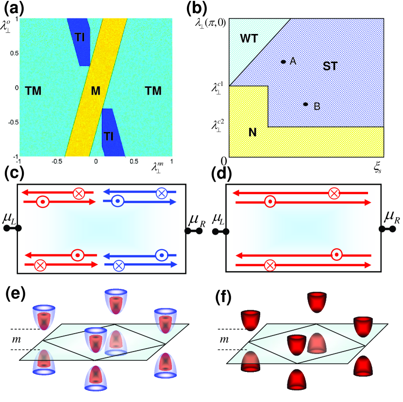
The phase diagrams for the topological transition are plotted in Fig. 5. In Fig. 5 (a), we plot the phase diagram for the case of the weak topological phase with respect to the parameters, and . Here, the topological metal phase means the hole-like band top at point is higher than the electron-like band bottom around point so that we cannot tune the system into a full insulating phase, but there is a gap at point to protect the topological phase. In the topological insulating phase, the edge states propagate along the edges of the materials with opposite speed for different spin components. The pictures of the edge states and the Dirac cones is schematically shown in Fig. 5 (c) and (e) respectively. In Fig 5.(b) we plot the phase digram for case with respect to the parameter in and . The A and B points correspond to the cases shown in Fig. 4. (c1) and (g1). The transport picture for the edge states is shown in Fig. 5 (d), which matches the single nontrivial Dirac cone structure shown in Fig. 5(f).
According to the aforementioned discussion, we see that the topological phase is associated to three key parameters: the trivial band gap, the intrinsic spin-orbital coupling strength at M points and the parity broken coupling induced by the substrates. In the FeSe, the bare spin-orbital coupling strength of Fe atoms is around 80Tiago2006-so , which can cause a bare energy splitting 100 around point. Considering the renormalization effect (about 4 in FeSe), the real splitting of the band caused by the SOC would be around 25mev. Although we may replace Fe by heavier atoms such as Ru to further increase the SOC strength, the strength of SOC, more or less, is a fixed quantity in the FeSe. However, the trivial band gap and parity-broken coupling at M point can be engineered. With different substrates, the in-plane lattice constant can be tuned from 3.67 to 4, which has been recently demonstrated in FeSe/STO/KTOPeng2014-prl and FeSe/BTOPeng2014-fese structures. There are a zoo of substrates to play for this interacial engineeringPeng2014-fese . In the supplement, we have shown the qualitative relationship between the gap and lattice parameters. An accurate quantitative prediction of the trivial band gap on different substrates are beyond the capability of any current numerical methods. Nevertheless, as we know that in one limit, the large band gap (about 50mev measured by ARPESPeng2014-fese ) is created in the SL FeSe with STO and BTO substrates, and in the other limit, it vanishes in the bulk FeSe, we can be sure that the interracial engineering technique can create a tunable gap in a SL FeSe. Furthermore, the parity-broken coupling can be larger when the interaction to a substrate is stronger. is tunable with large flexibility. Hence, realizing the topological phase in the SL FeSe is very promising.
It is also possible to further extend above analysis to the bulk materials. According to our above discussions, the difference of the electronic structures between the SL FeSe and the bulk FeSe mainly originates from the lattice distortion induced by the substrate, and the ratio between the height of Se to the Fe plane and the length of Fe-Fe bond uniquely measures this difference. When the ratio declines less than the threshold value, a band gap is opened around point. Experimentally, this ratio can be tuned through applying internal or external pressure to the materials. Therefore, we suggest that this topological transition may be realized in the bulk materials of iron-based superconductors if the intensity of SOC is comparable with the band gap around M point.
We also want to emphasize a great advantage to realize the topological phase in iron-based superconductors. Unlike the conventional hybridized system proposed to realize topological superconductorsQi2011-review and Majorana FermionFu2008-ts ; Lutchyn2010-mf in which the superconductivity is induced through the proximity effect of conventional s-wave superconductor with the low , the iron-based materials present high- superconductivity themselves, especially, the SL FeSe shows superconductivity at very high temperature. Hence, a significant importance of this study is to provide a realistic possibility to realize the stable Majorana Fermions at high temperature.
In conclusion, we show that the single layer FeSe present distinct and abundant structures compared with the bulk FeSe through the interaction with the substrates. We predict that there exists strong topological phase in the SL FeSe. It is conceivable that many important physics and applications can emerge when nontrivial topology meets the high- superconductivity.
The work is supported by the Ministry of Science and Technology of China 973 program(2012CB821400) and NSFC.
References
- (1)
- (2) Wang, Q. Y. et al. Interface-induced high-temperature superconductivity in single unit-cell fese films on srtio3. Chin. Phys. Lett. 29 (2012).
- (3) Liu, D. F. et al. Electronic origin of high-temperature superconductivity in single-layer fese superconductor. Nature Comm. 3 (2012).
- (4) He, S. L. et al. Phase diagram and electronic indication of high-temperature superconductivity at 65 k in single-layer fese films. Nature Materials 12, 605–610 (2013).
- (5) Tan, S. Y. et al. Interface-induced superconductivity and strain-dependent spin density waves in fese/srtio3 thin films. Nature Materials 12, 634–640 (2013).
- (6) Peng, R. et al. Critical role of substrate in the high temperature superconductivity of single layer fese on nb:batio3. arXiv:1402.1357 (2014).
- (7) Zhang, W. H. et al. Direct observation of high-temperature superconductivity in one-unit-cell fese films. Chin. Phys. Lett. 31 (2014).
- (8) Lee, J. J. et al. Evidence for pairing enhancement in single unit cell fese on srtio3 due to cross-interfacial electron-phonon coupling. arXiv:1312.2633 (2014).
- (9) Hsu, F. C. et al. Superconductivity in the pbo-type structure alpha-fese. PNAS 105, 14262–14264 (2008).
- (10) Yeh, K. W. et al. Tellurium substitution effect on superconductivity of the alpha-phase iron selenide. Epl 84 (2008).
- (11) Johnston, D. C. The puzzle of high temperature superconductivity in layered iron pnictides and chalcogenides. Adv. Phys. 59, 803–1061 (2010).
- (12) Dagotto, E. Colloquium: The unexpected properties of alkali metal iron selenide superconductors. Rev. Mod. Phys. 85, 849–867 (2013).
- (13) Subedi, A., Zhang, L., Singh, D. J. & Du, M. H. Density functional study of fes, fese, and fete: Electronic structure, magnetism, phonons, and superconductivity. Phy. Rev. B 78, 134514–134514 (2008).
- (14) Richard, P., Sato, T., Nakayama, K., Takahashi, T. & Ding, H. Fe-based superconductors: an angle-resolved photoemission spectroscopy perspective. Rep. Prog. Phys. 74 (2011).
- (15) Kuroki, K. et al. Unconventional pairing originating from the disconnected fermi surfaces of superconducting . Phys. Rev. Lett. 101, 087004–087004 (2008).
- (16) Graser, S., Maier, T. A., Hirschfeld, P. J. & Scalapino, D. J. Near-degeneracy of several pairing channels in multiorbital models for the fe pnictides. New J. Phys. 11, 5016–5016 (2009).
- (17) Hu, J. Iron-based superconductors as odd parity superconductors. Phys. Rev. X 3, 031004 (2013).
- (18) Hu, J. & Hao, N. S4 symmetric microscopic model for iron-based superconductors. Phys. Rev X 2, 021009 (2012).
- (19) Cvetkovic, V. & Vafek, O. Space group symmetry, spin-orbit coupling, and the low-energy effective hamiltonian for iron-based superconductors. Phys. Rev. B 88, 134510 (2013).
- (20) Lee, P. A. & Wen, X.-G. Spin-triplet p -wave pairing in a three-orbital model for iron pnictide superconductors. Phys. Rev. B 78, 144517–144517 (2008).
- (21) Kane, C. L. & Mele, E. J. Quantum spin hall effect in graphene. Phys. Rev. Lett. 95 (2005).
- (22) Bernevig, B. A., Hughes, T. L. & Zhang, S.-C. Quantum spin hall effect and topological phase transition in hgte quantum wells. Science 314, 1757 (2006).
- (23) Fu, L. & Kane, C. L. Topological insulators with inversion symmetry. Phys. Rev. B 76, 045302 (2007).
- (24) Fu, L. Topological crystalline insulators. Phys. Rev. Lett. 106, 106802 (2011).
- (25) Hsieh, T. H. et al. Topological crystalline insulators in the snte material class. Nature Comm. 3, 982 (2012).
- (26) Liu, C.-X. & Zhang, R.-X. Topological non-symmorphic crystalline insulators. arXiv:1308.4717 (2013).
- (27) Tiago, M. L., Zhou, Y., Alemany, M. M. G., Saad, Y. & Chelikowsky, J. R. Evolution of magnetism in iron from the atom to the bulk. Phys. Rev. Lett. 97, 147201 (2006).
- (28) Peng, R. et al. Enhanced superconductivity and evidence for novel pairing in single-layer fese on srtio3 thin film under large tensile strain. Phys. Rev. Lett. In press (2014).
- (29) Qi, X. L. & Zhang, S. C. Topological insulators and superconductors. Rev. Mod. Phys. 83 (2011).
- (30) Fu, L. & Kane, C. L. Superconducting proximity effect and majorana fermions at the surface of a topological insulator. Phys. Rev. Lett. 100 (2008).
- (31) Lutchyn, R. M., Sau, J. D. & Sarma, S. D. Majorana fermions and a topological phase transition in semiconductor-superconductor heterostructures. Phys. Rev. Lett. 105, 077001 (2010).