Multiple Scattering and Plasmon Resonance in the Intermediate Regime
Abstract
The collective excitation of the conduction electrons in subwavelength structures gives rise to the Localized Surface Plasmon(LSP). The system consisting of two such LSPs, known as the dimer system,is of fundamental interest and is being actively investigated in the literature. Three regimes have been previously identified and they are the photonic regime, the strong coupling regime and the quantum tunneling regime. In this Letter, we propose a new regime for this intriguing systems, the intermediate regime. In this new regime, the quasistatic approximation, which is widely used to study such LSP systems, fails to capture the main physics: the multiple scattering of the electromagnetic waves between the two LSPs, which significantly modifies the properties of the resonant modes in the system. This intermediate regime provides a new route to explore in plasmonics, where controlling both the excited plasmon modes and the damping rates are of paramount significance.
pacs:
73.20.Mf,03.65.Nk,78.67.BfThe collective excitation of conduction electrons in subwavelength structures is known as the Localized Surface Plasmon(LSP)a1 . Such plasmon modes have been intensively studied using noble metal nanoparticlesa2 ; a3 ; a4 ; a5 . More recently, the possibility of building terahertz metamaterials supporting such LSP modes is explored using graphene microribbonsa6 and microdisksa7 . LSP holds promise for applications in ultrasensitive biosensinga8 , nano-optical tweezersa9 and improved photovoltaic devicesa10 .
LSP arises when a subwavelength metal nanosphere is illuminated by light. This problem can be solved analytically within the quasistatic approximationa1 , where one ignores the phase retardation and solves the problem using electrostatics. Due to its simplicity, the quasistatic approximation has been widely applied to study systems involving LSPs a3 ; a4 ; a5 ; a6 ; b4 and powerful theoretical methods including transformation opticsb2 ; b3 and the hybridization modela5 ; b5 are developed under this approximation. However, by ignoring the phase retardation, one misses many potentially interesting effects arising from multiple scattering. In this Letter, we study such an effect in systems consisting of two weakly interacting LSPs, which is popularly known as the dimer system.
The dimer system is being actively explored in the literature due to its richness of fundamental physics and many potential applications . Three regimes have been identified:
In this Letter, we propose a new regime for this dimer system, the intermediate regime, which arises when . This regime was previously named the weak coupling regime in Ref.b3 and it was argued within the quasistatic approximation that the dimer system in this regime should exhibit the same behavior as individual LSPs, meaning that only a single symmetric mode can be observed. This quasistatic argument would be correct if the two nanoparticles are non-resonant scatters of the incident light. However, the LSPs are by nature resonant scattering modesa1 with scattering cross section scaling as a1 ; a11 . For nanoparticles with D¡20nm, this scattering cross section can be 10000 times larger than their physical sizesa2 . If two such nanoparticles are placed within one wavelength, one can expect multiple scattering to yield new interesting physics in certain regimes. In quantum scattering theory, multiple scattering between two resonant scatters gives rise to the proximity resonancea11 . Due to the distinctive resonant properties of LSPs, multiple scattering displays a different signature in this plasmonic dimer system.
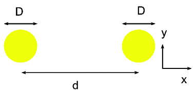
In the following, we first consider the dimer system illuminated by an incoming plane wave polarized in the y direction and propagating in the x direction. For nanoparticles with , the LSPs can be well described by two resonant dipoles, , a1 ; b3 ; d2 , where are the positions of the two nanoparticles. These two dipoles have to satisfy the following self-consistent equations:
| (1) | ||||
, where is the dynamic electric polarizability tensor, is the incoming wave and is the interaction tensor defined asd2 ; a12
| (2) |
and k is the light momentum in free space.
A direct expansion of (1) yields
| (3) | ||||
, from which it is clear that includes contributions from both the incoming wave and all the waves that are scattered by the nanoparticle at and eventually return to . These include all the possible multiple scattering paths between the two nanoparticles.
For our setup, the solutions to (1) can be written as the sum of a symmetric part and an antisymmetric part:
| (4) | ||||
, where and are the diagonal elements corresponding to the y directions, of the polarizability tensor and the interaction tensor respectively.
With this definition, the solutions are given by
| (5) |
As is clear from (4), new resonant modes arise when , corresponding to a symmetric and an antisymmetric mode respectively. The physical origin of these two resonant modes are different from those in the photonic regime and the strong coupling regime. In the photonic regime, an antisymmetric mode could arise if , which corresponds to a phase matching condition. However, the antisymmetric mode in this intermediate regime arises when . In this case, the phase accumulation due to multiple scattering enables the excitation of the antisymmetric mode for subwavelength separation between the two nanoparticles. In the strong coupling regime, the antisymmetric mode arises as a result of the hybridization of the individual dipole modesa5 , which requires the separation d to be smaller than twice of the diameter of the nanoparticlesb3 . This condition corresponds to for a2 and this mode gains strength as this ratio increasesb10 . However, the antisymmetric mode in the intermediate regime can arise for and loses strength as this ratio increases. More importantly, the antisymmetric mode in the strong coupling regime can arise within the quasistatic approximationb3 where phase retardation is completely ignored. However, as we will demonstrate below, the antisymmetric mode in the intermediate regime will completely disappear in the quasistatic limit, which clearly points to a different origin from that in the strong coupling regime.
For nanoparticles supporting LSPs, can be written as
| (6) |
where is the single LSP resonance frequency, is the total damping rate and is the radiative contribution to . This form has the merits of satisfying both the optical theorem and causality in the absence of absorptiona13 ; a14 .
If we define and keep only the leading terms, we find the following simplified expressions for the resonant frequency and damping rate for the antisymmetric mode:
| (7) | ||||
For the symmetric mode, the results are
| (8) | ||||
The above formula implies that, under certain conditions, the damping rate of the antisymmetric mode can increase above the single LSP damping rate , while the damping rate of the symmetric mode can drop below . These conditions are , , which can be easily satisfied by gold nanoparticles as shown below.
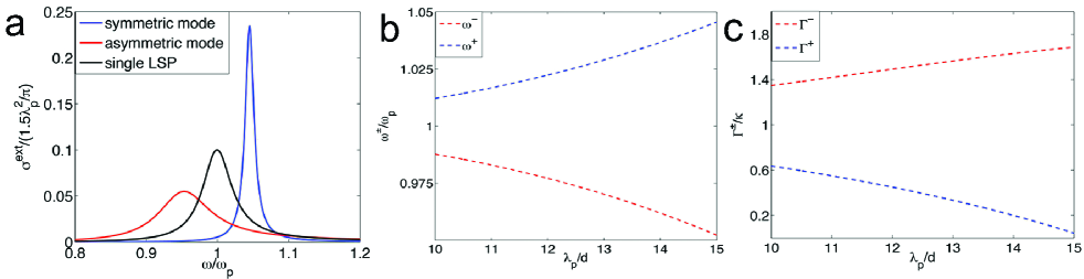
In Fig.2, we plot the extinction cross section for each moded3 , the resonance frequencies and the damping rates as a function of , where is the wavelength of the exciting light at the single LSP frequency. In these calculations, is fixed to be and is assumed to be 20, which are chosen based on a previous experiment on gold nanoparticles with a2 . When , the damping rate of the antisymmetric mode is boosted by a factor of 1.8, while the damping rate of the symmetric mode is reduced by a factor of 5. Combined with a 10 splitting in the resonant frequencies, the two modes can be easily distinguished in an experimental setup. Even though the antisymmetric mode is weaker than the symmetric mode, it is still greatly enhanced by multiple scattering. As one can see from Fig.2a, the resonance peak for the antisymmetric mode is only smaller than the single LSP resonance peak by a factor of about two. Since the single LSP resonance is strong enough to enable single molecule detectiond4 , the antisymmetric mode in this intermediate regime is clearly strong enough to have observable effects.
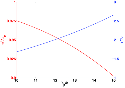
As mentioned above, what distinguishes this antisymmetric mode in the intermediate regime from that in the strong coupling regime is its reliance on the phase retardation in the incident field. If the phase retardation is removed by changing the polarization of the incident light( and ), the antisymmetric mode is completely suppressed and only the symmetric mode can be excited. The resonance frequency and the damping rate for the symmetric mode in this case are found to be
| (9) | ||||
These relations are plotted in Figure 3 using the same parameters as before. In this case, the symmetric mode instead displays enhanced damping.
To summarize, we introduce a new intermediate regime for studying the plasmon dimer system, where multiple scattering has the dominant effect. We show that one can excite the antisymmetric mode by direct light illumination. It was previously believed that this antisymmetric mode,important for plasmon-induced transparencyb7 and three-dimensional plasmon rulersb8 , can’t be excited by the incident light in this ”weak coupling” regime and one has to resort to either electron beamc1 or designed structures with broken symmetryb1 ; b6 ; b7 ; b8 to activate it. More importantly, we show that multiple scattering can lead to significant changes in the damping rates of the plasmon modes in this new regime. The damping rate of the symmetric mode, a highly radiating mode, can be reduced by a factor of five, while the damping rate of the antisymmetric mode, a subradiant mode, is enhanced above the single LSP damping rate. This could be important for many practical applications, such as Surface-Enhanced Raman Scatteringb9 , improved photovoltaic devicesa10 , optical emittersb10 ; b11 and plasmon waveguidesb12 . But most importantly, manipulating plasmon modes and their damping rate are of key importance in the field of plasmonics, and our results provide a new route to explore to this end.
We thank Prof. Federico Capasso for valuable discussions and acknowledge financial support from the U.S. Department of Energy under Grant DE-FG02-08ER46513.
References
- (1) S.A. Maier, Plasmonics: Fundamentals and Applications, Springer: New York,2007.
- (2) C. Sonnichsen, T. Franzl, T. Wilk, G. von Plessen, J. Feldmann, O. Wilson, P. Mulvaney, Phys. Rev. Lett. 88, 077402(2002).
- (3) S. Eustis, M. A. El-Sayed, Chem. Soc. Rev.35, 209(2006).
- (4) N. J. Halas, S. Lal, W. Chang, S. Link, P. Nordlander, Chem. Rev. 111, 3913(2011).
- (5) E. Prodan, C. Radloff, N. J. Halas, P. Nordlander, Science 302, 419(2003).
- (6) L. Ju, B. Geng, J. Horng, C. Girit, M. Martin, Z. Hao, H. A. Bechtel, X. Liang, A. Zettl, Y. R. Shen, F. Wang, Nature Nanotechnology 6, 630(2011).
- (7) H. Yan, X. Li, B. Chandra, G. Tulevski, Y. Wu, M. Freitag, W. Zhu, P. Avouris, F. Xia, Nature Nanotechnology 7, 330(2012).
- (8) A. G. Brolo, Nature Photonics 6, 709 (2012).
- (9) M. L. Juan, M. Righini, R. Quidant, Nature Photonics 1, 641 (2007).
- (10) H. A. Atwater, A. Polman, Nature Materials 9, 205–213 (2010).
- (11) J. Zuloaga, E. Prodan, P. Nordlander, Nano Lett. 9, 887(2009).
- (12) A. Aubry, D. Y. Lei, A. I. Fernandez-Dominguez, Y. Sonnefraud, S. A. Maier, J. B. Pendry, Nano Lett. 10, 2574(2010).
- (13) A. Aubry, D. Y. Lei, S. A. Maier, J. B. Pendry, Phys. Rev. Lett. 105, 233901(2010).
- (14) P. Nordlander, C. Oubre, E. Prodan, K. Li, M. I. Stockman, Nano Lett. 4, 899(2004).
- (15) E. M. Hicks, S. Zou, G. C. Schatz, K. G. Spears, R. P. Van Duyne, L. Gunnarsson, T. Rindzevicius, B. Kasemo, and M. Kall, Nano Lett. 5 1065(2005).
- (16) S. Kim, J. Jin, Y. J. Kim, I. Y. Park, Y. Kim, S. W. Kim, Nature 453, 757(2008).
- (17) S. Thongrattanasiri, F. H. L. Koppens, F. J. Garcia de Abajo, Phys. Rev. Lett. 108, 047401(2012).
- (18) D. V. van Coevorden, R. Sprik, A. Tip, A. Lagendijk, Phys. Rev. Lett. 77, 2412(1996).
- (19) E. J. Heller, Phys. Rev. Lett. 77, 4122(1996).
- (20) K. J. Savage, M. M. Hawkeye, R. Esteban, A. G. Borisov, J. Aizpurua, J. J. Baumberg, Nature 491, 574(2012).
- (21) F. Javier Garcia de Abajo, Rev. Mod. Phys. 79, 1267(2007).
- (22) J. D. Jackson, Classical Electrodynamics, John Wiley Sons: New York, 1998.
- (23) M. Chu, V. Myroshnychenko, C. H. Chen, J. Deng, C. Mou, F. Javier Garcia de Abajo, Nano Lett. 9,399(2009)
- (24) The total extinction cross section for this system is found to be , where and . We can define as the extinction cross section for the symmetric mode and as the extinction cross section for the antisymmetric mode.
- (25) S. Nie and S. R. Emory, Science 275, 1102(1997).
- (26) S. A. Maier, Nature Materials 8, 699(2009).
- (27) P. Nordlander, ACS Nano 3, 488(2009).
- (28) N. Liu, L. Langguth, T. Weiss, J. Kastel, M. Fleischhauer, T. Pfau, H. Giessen, Nature Materials 8, 758(2009).
- (29) N. Liu, M. Hentschel, T. Weiss, A. P. Alivisatos, H. Giessen, Science 332, 1407(2011).
- (30) A. Wokaun, J. P. Gordon, P. F. Liao, Phys. Rev. Lett. 48, 957(1982).
- (31) J. A. Schuller, E. S. Barnard, W. Cai, Y. C. Jun, J. S. White, M. L. Brongersma, Nature Materials 9, 193(2010).
- (32) S. A. Maier, P. G. Kik, H. A. Atwater, S. Meltzer, E. Harel, B. E. Koel, A. A. G. Requicha, Nature Materials 2, 229(2003).