Chromatic Dispersion Compensation Using Filter Bank Based Complex-Valued All-Pass Filter
Abstract
A long-haul transmission of Gb/s without optical chromatic-dispersion (CD) compensation provides a range of benefits regarding cost effectiveness, power budget, and nonlinearity tolerance. The channel memory is largely dominated by CD in this case with an intersymbol-interference spread of more than symbol durations. In this paper, we propose CD equalization technique based on nonmaximally decimated discrete Fourier transform (NMDFT) filter bank (FB) with non-trivial prototype filter and complex-valued infinite impulse response (IIR) all-pass filter per sub-band. The design of the sub-band IIR all-pass filter is based on minimizing the mean square error (MSE) in group delay and phase cost functions in an optimization framework. Necessary conditions are derived and incorporated in a multi-step and multi-band optimization framework to ensure the stability of the resulting IIR filter. It is shown that the complexity of the proposed method grows logarithmically with the channel memory, therefore, larger CD values can be tolerated with our approach.
I Introduction
The performance of fiber optic links in long haul, metro and enterprise networks became limited by chromatic dispersion causing a short optical pulse to broaden as it travels along the fiber leading to intersymbol interference (ISI). To mitigate the effects of dispersion, optical systems include some form of CD compensation either electronically, optically or digitally. Digital equalization is attractive because it is less expensive, flexible and robust to varying channel conditions compared to electronic and optical.
CD has a time-invariant transfer function and only effects the phase of the input signal, i.e., it exhibits an all-pass behavior. In [2], G. Goldfarb and G. Li suggested dispersion compensation (DC) using time domain equalizer (TDE) technique based on infinite impulse response (IIR) all-pass filter. Their methodology requires Hilbert transformer and time reversal operation to design real-coefficients IIR filter separately for real and imaginary part of the transmitted signals. This technique was improved by J. Munir et al. [3] in which an optimization framework was presented to design stable complex-valued IIR all-pass filter. Computational complexity of this scheme is less compared to [2] as it doesn’t require the use of Hilbert transformer. However TDE schemes are not feasible for very long optical link as their complexity increases linearly with the channel memory.
Frequency domain equalizers (FDEs) based on fast Fourier transform (FFT) have become the most appealing scheme for CD compensation due to the low computational complexity for large dispersion and the wide applicability for different fiber distances [5]. In state-of-the-art FDE CD compensation design, the size of the FFT to realize fast linear convolution is governed by the specification of the maximum channel memory length with two-fold oversampling and block overlap [4]. Nevertheless, the overlap-save method can be regarded not just as fast convolution method but also as a FB structure with trivial prototype filters and the equalization is done per sub-band, opening the way for more sophisticated sub-band processing [6]. Based on this observation, we propose CD equalization technique based on NMDFT FB with non-trivial prototype filter and complex-valued IIR all-pass filter per sub-band.
The main contribution of the paper is the presentation of an optimization framework to design stable sub-band complex-valued IIR all-pass filter for CD equalization. Root-raised-cosine (RRC) filter is chosen as a non-trivial prototype filter and optimal filter length and roll-off to achieve certain bit-error-rate (BER) are also investigated. It is shown that the complexity of our approach increases logarithmically with the channel memory. The paper is organized as follows. Section II introduces the channel transfer function for CD. Section III describes the equalizer description based on IIR filtering and its complexity analysis. FB based sub-band equalizer design is presented in Section IV and necessary condition for stability and filter order of individual sub-bands are derived in Section V. Two design criteria presented in an optimization framework [3] are modified in Section VI for sub-band equalizer design. Comlexity analysis of the proposed scheme is derived in Section VII. Simulation results comparing IIR and FB based IIR filtering are presented in Section VIII. Conclusions are given in Section IX.
II Channel Model
The low-pass equivalent model of CD channel of a single mode fiber of length can be written as
| (1) |
where , , and are baseband radial frequency, operating wavelength, fiber dispersion parameter and speed of light, respectively. If we sample the signal by sampling frequency Hz, then the equivalent model in discrete domain can be represented as
| (2) |
where and . It is clear from (2) that the CD channel has an all-pass characteristic, i.e., it only changes the phase of the input signal.
III Equalizer Design
The transfer function of an ideal equalizer to compensate CD channel is obtained by taking the inverse of (2)
| (3) |
Since the CD channel exhibits an all-pass behavior, therefore, the natural choice to equalize it by the cascade of first order IIR all-pass sections of the form
| (4) |
where and are the radius and angle of the pole location in the complex -plane. Each first order section of complex valued IIR all-pass filter can be efficiently realized by four real multiplications as shown in Fig. 1. It was shown in [3] that the required filter order is given as
| (5) |
It can be seen from above relation that the increases linearly with the fiber length which is not feasible to equalize very long optical links. In order to extend this framework to equalize long optical channels, we present FB based complex-valued all-pass equalizer design.
IV Filter Bank based Complex Valued Sub-band All-Pass Equalizer
Fig. 2 and Fig. 3 illustrates the efficient implementation of NMDFT filter bank structure [7] with RRC filter as a non-trivial prototype filter of length where is a positive integer number. The polyphase components of the RRC filter in the analysis filter bank (AFB) and synthesis filter bank (SFB) are and respectively. The basic idea is to divide the incoming signal into frequency bands after filtering and downsampling operation in AFB and design IIR all-pass CD equalizer for every sub-band. The complexity of the overall structure is reduced since each frequency band is operating at a lower rate . The choice of is independent of channel memory which can be advantageous from hardware implementation perspective.
V Complex Valued Sub-band All-Pass Equalizer Design
Transfer function of the sub-band IIR all-pass filter has the form
| (6) |
The design strategy for each sub-band all-pass equalizer will be same as described in [3]. But we consider it important to derive the phase response and group delay as seen by every sub-band. Based on the group delay behavior, we will describe the stability criteria and the optimum number of stages for every sub-band.
V-A Phase Response And Group Delay
Transfer function of the CD channel in the sub-band after filtering and downsampling operation is given by
| (7) |
where , , and . Transfer function of an ideal equalizer to compensate CD channel is obtained by taking the inverse of (7)
| (8) |
Phase response and group delay for the sub-band of an ideal equalizer takes the following form
| (9) |
| (10) |
Negative group delay implies an unstable all-pass filter [9], therefore, constant is added to the ideal group for all the sub-bands to make non-negative desired group delay function, i.e.,
| (11) |
where
| (12) |
Desired phase takes the form
| (13) |
Here is a constant of integration and it will be calculated in the optimization framework.
V-B Filter Order
Filter order for the sub-band is obtained by integrating its desired group delay function (11)
| (14) |
But the integral of the desired group delay is given by
| (15) |
Comparing above two equations yields ,
| (16) |
VI Design Criteria For the Sub-Band All-Pass Filters
We will use the same optimization framework as described in [3] for the design of sub-band filter with the following modifications in the cost functions.
VI-A Phase Transfer Cost Function,
The objective is to design sub-band IIR all-pass equalizer whose phase response matches the desired phase response of (13). Therefore, product of a sub-band all-pass equalizer and the sub-band CD channel has to be ideally
We will define error transfer function as
Weighted MSE in phase transfer can be written as
Therefore, optimization problem takes the form of minimizing the metric
| (17) | ||||
VI-B Group Delay Cost Function,
Weighted MSE for the sub-band in terms of group delay can be written as
| (18) |
Therefore, optimization problem takes the form of minimizing the metric
| (19) |
Fig. 4 depicts the flow chart of FB based IIR all-pass sub-band optimization framework.
VII Complexity Analysis
Complexity of the IIR equalizer in terms of real multiplications is given by
If we implement IIR in the sub-band domain then the complexity reduces by a factor since each sub-band is running at a lower rate. But at the same time, the overall filter order increases by an overlapping factor which is 2 in this case. Therefore, complexity of IIR with the FB is given by
| (20) |
Total complexity of the NMDFT FB (AFB and SFB) [8] and IIR is given as
| (21) |
In (21), the only variable is the number of sub-bands and minimum value of is obtained by setting the derivative of (21) with respect to to zero and solving it to find the optimal value of , i.e.,
| (22) |
Substituting in (21), we will get
| (23) |
which increases logarithmically with .
VIII Simulations
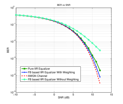
A GBaud QPSK transmission with digital coherent receiver applying two-fold oversampling with GS/s is used to verify our technique for CD equalization. System parameters are nm, ps/nm/km, km, and . Same weighting function is used in the optimization framework since the prototype filters in all the sub-bands have same spectral shape. Fig. 5 shows the BER comparison between FB based sub-band IIR equalization and pure IIR equalization. In the first set of simulation, FB based sub-band equalizer with uniform weighting in each sub-band is used and BER is calculated. It can seen from the figure that it has worse performance compared to pure IIR equalization. In the second set of simulations, FB based sub-band equalizer with squared magnitude RRC weighting function is used. BER simulations are carried out for different cut-off frequencies and roll-off factor. We found out the optimal parameters are and roll-off is for squared magnitude RRC weighting function. Fig. 5 shows the improvement with the weighting function and it slightly outperform the pure IIR equalization.
Complexity of a FB based processing depends on the length of non-trivial prototype filter and it is reflected in the parameter in (21). In our proposed FB structure, the prototype is the RRC filter with fixed cut-off frequency but roll-off is a design parameter. Length of prototype filter should be very large for small roll-off factor and vise versa. All the simulation till this point are reported for roll-off factor of and filter length of . We are interested in reducing the length of prototype filter with very small loss in BER performance. Table I shows the effect of reducing the length for two cases. From these observations, we conclude that the roll-off factor of RRC filter for other values should also be takes as a design parameter in the optimization framework.
| Roll-Off | SNR at BER | |
|---|---|---|
| 0.2 | 256 | 10.1 |
| 128 | 11.2 | |
| 0.9 | 256 | 10.1 |
| 128 | 10.1 | |
| 64 | 10.2 |
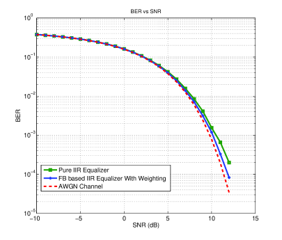
One of the major advantage of our methodology compared to the existing ones is the flexibilty in selecting the number of sub-bands . Based on the simulation setting mentioned earlier, the optimum number of sub-band is according to (22). Fig. 6 shows BER results for and it is almost the same as that of .
IX Conclusions
We presented NMDFT FB based framework with RRC prototype filters in the AFB and SFB to design sub-band IIR all-pass filters for CD compensation. Necessary conditions based on group delay characteristic are derived to select minimum filter order and stability of the resulting sub-band IIR all-pass filters. An optimization scheme presented in [3] is used to find the coefficients of the sub-band IIR all-pass filters. Very long optical links can be compensated by this method as the complexity increases logarithmically with the fiber length. Simulation result show that BER performance of the proposed method with appropriate selection of weighting function in the optimization framework is better compared to pure IIR equalization. Additionally we show that a compromise between complexity and performance can be reached by selecting roll-off factors and filter lengths of the RRC prototype filter. One of the advantage offered by our scheme over FDE is the flexibility in selecting which might be attractive from hardware implementation point of view. It is left as a future work to compare the complexity and performance comparison between FDE equalization and our proposed scheme.
References
- [1] M. G. Taylor, “Coherent detection method using DSP for demodulation of signal and subsequent equalization of propagation impairments,” IEEE Photon. Technol. Lett., vol. 16, no. 2, pp. 674-676, Feb. 2004.
- [2] G. Goldfarb, and G. Li, “Chromatic dispersion compensation using digital IIR filtering with coherent detection,” IEEE Photon. Technol. Lett., vol. 19, no. 13, pp. 969-971, Jul. 2007.
- [3] J. Munir et al., “Chromatic dispersion compensation using complex-valued all-pass filter,” in 22nd European Signal Processing Conference 2014.
- [4] K. Ishihara et al., “Frequency-domain equalisation without guard interval for optical transmission systems,” Electron. Lett., vol. 44, no. 25, pp. 1480-1482, Dec. 2008.
- [5] K. Ishihara et al., “Frequency domain equalization for coherent optical transmission systems,” in OFC/NFOEC 2011.
- [6] I. Slim, et al., “CD equalization with non-maximally decimated DFT filter bank,” in Proc. IPC 2012, Burlingame, CA, Sep. 2012, p. 173.
- [7] I. Slim, et al., “Delayed single-tap frequency-domain chromatic-dispersion compensation,” IEEE Photon. Technol. Lett., vol. 25, no. 2, Jan. 2013.
- [8] T. Karp and N. Fliege, “Modified DFT filter banks with perfect reconstruction,” Circuits and Systems II: Analog and Digital Signal Processing, IEEE Transactions, vol. 46, no.11, pp. 1404-1414, Nov. 1999.
- [9] J.S. Abel, and J.O. Smith, “Robust design Of very high-order allpass dispersion filters,” 9th Int. Conference on Digital Audio Effects (DAFx-06)., Montreal, Sep. 2006.