Optoelectronic down-conversion by four-wave mixing in a highly nonlinear fiber for millimeter-wave and THz phase-locking
Abstract
Optoelectronic down-conversion of a THz optical beatnote to a RF intermediate frequency is performed with a standard Mach-Zehnder modulator followed by a zero dispersion-slope fiber. The two interleaved optical spectra obtained by four-wave mixing are shown to contain more than 75 harmonics enabling to conveniently recover the phase noise of a beatnote at 770 GHz at around 500 MHz. This four-wave mixing down-conversion technique is implemented in a two-frequency solid-state laser in order to directly phase-lock its 168 GHz beatnote to a 10 MHz local oscillator.
[Second University]
Institut de Physique de Rennes, Département d’Optique et Photonique, UMR CNRS-Université de Rennes 1 6251,
Campus de Beaulieu, Rennes cedex 35042, FRANCE
Ultra-high resolution spectroscopy 1, THz metrology 2, or THz radio-astronomy 3, 4 are applications that need ultra-stable continuous-wave (cw) sources. While heterodyning two continuous optical waves in a photo-detector is a well-established approach to generate cw THz signals, stability usually relies on phase-locked loops (PLL) 5, 6, 7, 8. When the heterodyne beat is at THz frequencies, the major issue is to down-convert the THz beat to RF frequencies in order to implement standard PLLs. In this perspective, an important experimental step up was made recently by using a nonlinear electro-optic modulator (EOM) to bridge the gap between widely spaced optical frequencies. The opto-electronic phase locked-loop principle (OEPLL) principle was successfully implemented to stabilize two-frequency laser beat signals at 100 GHz 9, 10, up to 250 GHz 11 in an improved set-up, and also to stabilize microcombs at 140 GHz mode spacing 12. In all cases, the frequency spacing is limited to the number of harmonics that the EOM can generate, typically 10.
Besides, four-wave mixing in optical fibers is an optical nonlinear effect which has been studied extensively for applications such as telecommunication when several optical carriers propagate simultaneously in the fiber 13. In particular, the benefit of using this effect has been shown for the generation of optical frequency combs 14. Indeed, a dispersion management in the fiber allows to generate very wide comb 15. Moreover, the use of a zero-dispersion-slope highly nonlinear fiber offer an important potentiality to generate wide and flat optical frequency combs 16, 17, 18, 19. Thus, One can wonder if this nonlinear effect could be advantageously implemented to achieve an optoelectronic down-conversion from the THz to the RF band for the purpose of detecting an intermediate frequency which give access to the THz phase noise.
In this letter we report on a new solution including a highly non-linear fiber (HNLF) to bridge the wide frequency gap between the THz and GHz domains. Actually, by sending a two-frequency beam into the HNLF, one expects to generate two interleaved frequency combs which should give access to an intermediate frequency signal carrying the THz phase noise.
The principle of the experimental setup is depicted in Fig.1(a). It involves two independent lasers or a single laser providing two optical frequencies, and , whose difference is in the THz range. The two beams are combined and then focused into a polarization-maintaining (PM) fiber. Contrary to our previous work in which a dedicated nonlinear electrooptic modulator (EOM) was required 9, we now use a standard EOM. This EOM is driven at leading to the generation of two sidebands around and . In order to optimize the four-wave mixing (FWM) efficiency in the HNLF, an erbium-doped fiber amplifier (EDFA) follows the EOM. The optical power sent into the 100 m-long HNLF fiber can thus be adjusted from 20 dBm to 28 dBm. Note that the HNLF dispersion slope is chosen close to 0 ps/(nm2.km), which is required to achieve optimal phase matching of the generated frequency combs 16. Finally, we adjust the bias voltage of the modulator, as well as the RF power in order to maximize the efficiency of the frequency comb generation.
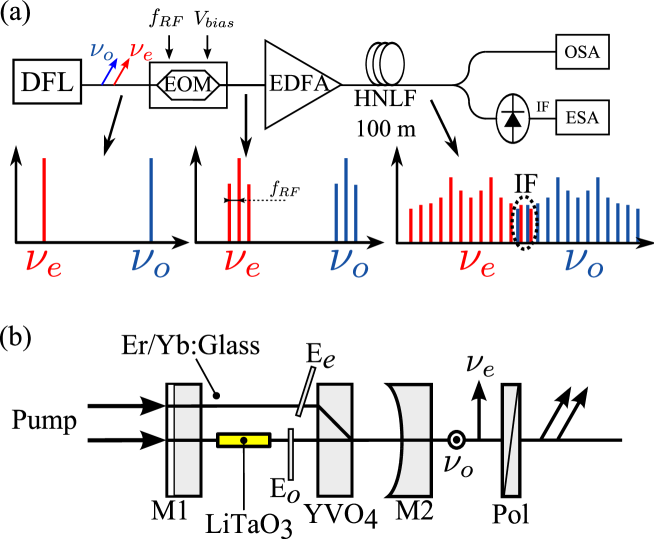
In our experiment, the two optical frequencies are provided by a two-propagation-axis laser schematized in Fig.1(b). The active medium is a 1.5-mm-long phosphate glass doped Er/Yb. The resonator is closed by the input mirror M1 directly coated on the external face of the active medium and by a 5-cm radius of curvature mirror. Due to an anti-reflection coated 10-mm-long YVO4 crystal (cut at 45∘ of its optical axis) inserted into the cavity, two orthogonally polarized eigenmodes (labeled respectively o and e) are separated by 1 mm in the active medium while superimposed at the output coupler. The active medium is pumped at 980 nm using a laser diode. In order to efficiently pump the two eigenmodes, the pump beam is split into two parallel 400-mW 100 m-diameter beams separated by 1 mm. To this aim, a second YVO4 crystal (not shown in the figure) is inserted between the pump focusing lens and the laser input mirror. To ensure single mode oscillation of each eigenpolarization and to adjust independently their wavelengths, we insert two 40 µm-thick silica etalons (Ee and Eo ) coated on both sides for 30 % reflection at 1550 nm. Such a cavity architecture leads to the simultaneous oscillation of two tunable wavelengths which are linearly cross-polarized. By tilting the etalons, we are able to tune independently the two wavelengths over the whole erbium gain bandwidth. It leads to a beatnote adjustable between a few MHz and 2 THz 20, 21. Here we keep Eo perpendicular to the ordinary propagation axis while Ee is tilted to sweep the frequency difference . Furthermore, a LiTaO3 electrooptic crystal is inserted on the ordinary path of the cavity offering a continuous tunability of the beatnote. This laser is consequently turned into a THz voltage controlled oscillator 9. The TEM00 laser output beam is sent through a polarizer oriented at 45∘ in order to make the two modes beating before entering the EOM.
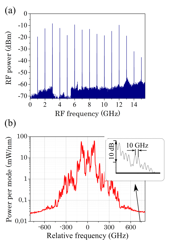
Experimental results are presented in Fig. 2. In order to evaluate the electrical spectrum of the generated combs, we first send through the EOM one optical frequency and we turn to a low frequency (1 GHz). Fig. 2(a) displays the 15 first harmonics of observed with a 16 GHz bandwidth photodiode after propagation along the HNLF. The frequency comb has a quite flat amplitude, which greatly improves previous achievements using a nonlinear EOM or a phase modulator 9, 10. Although is low, the entire comb cannot be displayed because of the limited cut-off frequency of our photodiode. To observe higher harmonics and then evaluate the comb span, we now set the frequency modulation at 10 GHz and monitor the comb in the optical domain. The generated comb spans 1 THz leading to measurable lines up the 75th harmonics, as shown on the optical spectrum of Fig. 2(b) .
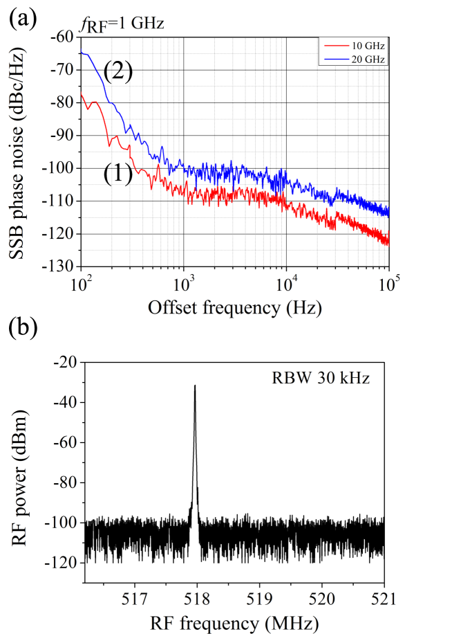
An accurate spectral analysis of the comb lines is performed by measuring the RF phase noise of the different harmonics numbered N. To this aim, we turn again to a modulation frequency of 1 GHz. For illustration purpose, two phase noise spectra for (1) = 10 (10 GHz) and (2) = 20 (20 GHz) are reported in Fig. 3(a). The expected phase noise degradation of 22 is confirmed experimentally. One can thus conclude that the 100m-long fiber does not bring additional noise degradation at least for the first 20th harmonics generated by FWM. Let us remind here that our goal is to down convert a THz beatnote in the GHz range. We now send to the modulator the two optical frequencies at the same time. Setting the frequency difference of the laser to 770 GHz, we were able to measure an intermediate frequency between the interleaved combs at around 500 MHz (see Fig. 3(b)). A dynamic range as high as 70 dB is then obtained on this intermediate frequency with a 30 kHz measurement bandwidth. This high dynamic range makes it possible to evaluate the spectral purity of the THz beatnote without any electrical component operating in the THz range. Indeed, the highest cut-off frequency in the experiment is that of the EOM, i.e., 10 GHz. Although demonstrated with a dual frequency laser, this FWM-assisted down-conversion technique is obviously well suited for two independent solid-state or semiconductor lasers. Moreover, the technique demonstrated here involves only widely spread and commercially available components in contrast to ref 9.
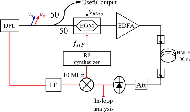
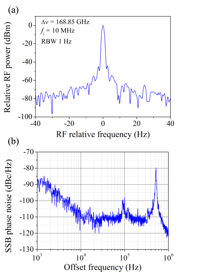
Now, one can wonder if we can use this approach in order to actively stabilize the optical beatnote through the generated intermediate frequency. To this aim, we implement the experimental servo-loop depicted in Fig. 4. For the purpose of phase locking , it is convenient to down convert the laser beatnote directly to = 10 MHz, i.e., at the frequency of the quartz oscillator that will be used as frequency reference. This is obtained by adjusting precisely the modulation frequency . We then electrically mix with the 10 MHz reference quartz oscillator of the RF synthesizer leading to a DC voltage proportional to the phase error. Through a loop filter (100 kHz bandwidth), we finally apply the error signal on the LiTaO3 crystal located inside the laser cavity. The laser frequency difference is set at around 170 GHz. We have chosen this value for OEPLL demonstration purpose, instead of 770 GHz as before, because our laser was actually optimized in terms of optical power and long-term stability for optimal operation around 100 GHz. To make the intermediate frequency close to 10 MHz, the EOM frequency has to be adjusted to 10.5525 GHz. The value of the frequency difference being given by , where N is the locking harmonic order, its exact value is actually 168.85 GHz with 8. By closing the loop we stabilize the intermediate frequency and, consequently, the frequency difference . This result is reported in Fig. 5. Fig. 5(a) displays the electrical spectrum of the intermediate frequency when the loop is closed. The full width at half maximum is measured to be lower than 1 Hz limited by the resolution of our electrical spectrum analyzer. This leads to an in-loop relative instability / at the 10-11 level. As already mentioned, the signal-to-noise ratio is greatly improved as compared to the results presented in Ref. 9, 80 dB here. It is worthwhile to notice that the spectral purity of the stabilized beatnote is governed by the spectral purity of the RF synthesizer delivering and the 10 MHz reference. To evaluate precisely the noise closer to the carrier, we measure now the single sideband (SSB) phase noise of the intermediate frequency (see Fig. 5(b)). The absolute phase noise is found to be 110 dBc/Hz at 10 kHz from the carrier. However, one can notice a resonant noise at 550 kHz whose origin is still not identified. Indeed, this frequency corresponds neither to the relaxation oscillation frequency of the laser (90 kHz) nor to the free spectral range of the optelectronic loop which is estimated at around 180 kHz. Further studies are actually devoted to figure out the origin of this excess noise.
In conclusion, we propose and demonstrate an optoelectronic down-conversion of a THz beat note to RF frequencies using four-wave mixing in a highly nonlinear fiber. This principle is illustrated using a dual frequency laser whose frequency difference is set at 770 GHz. Two interleaved combs are then generated around each optical carrier using a standard Mach-Zehnder modulator at 10 GHz followed by a highly nonlinear zero dispersion slope fiber. These combs are shown to contain more than 75 harmonics offering an intermediate frequency in the MHz range with an SNR of 70 dB. Moreover we show that the four wave mixing mechanism does not bring any additional degradation of the measured phase noise, at least up to the 20th harmonic. Hence, the intermediate frequency gives access to the phase noise of the THz beatnote using only commercially available optoelectronic components operating at room temperature. Although demonstrated using a dual frequency laser, the proposed down conversion technique could apply to a couple of detuned single mode lasers including semiconductor lasers.
In a second part, this four-wave mixing down-conversion technique is advantageously implemented in an optoelectronic phase locked loop in order to directly phase-lock the laser beat note at 168 GHz to a 10 MHz local oscillator. The beat note linewidth is then reduced down to 1 Hz corresponding to an in-loop relative instability of 10-11 . In these conditions, the phase noise level is measured to be 110 dBc/Hz at 10 kHz from the carrier and is shown to be limited by the RF synthesizer phase noise. This second part of the work is a new step for the generation of ultra- high spectral purity THz waves. Further studies include a detailed analysis and understanding of the resonant phase noise we observed at 500 kHz from the carrier and which is still unexplained. Moreover, out-of-loop measurements will be undertaken in order to fully characterize the stability of the THz beatnote. According to the significantly high down-conversion SNR offered by this four wave mixing approach, the phase locking of two independent lasers is now envisaged using a loop filter with increased bandwidth.
The authors are very grateful to Goulc’hen Loas, Ludovic Frein, Cyril Hamel, Steve Bouhier and Anthony Carré for their help. This work is partially funded by Région Bretagne, Rennes Métropole, FEDER, and DGA.
References
- Tonouchi 2007 Tonouchi, M. Nature Photonics 2007, 1, 97–105
- Popovic and Grossman 2011 Popovic, Z.; Grossman, E. Terahertz Science and Technology, IEEE Transactions on 2011, 1, 133–144
- Cliche and Shillue 2006 Cliche, J.-F.; Shillue, B. Control Systems, IEEE 2006, 26, 19–26
- Mayorga et al. 2012 Mayorga, I.; Schmitz, A.; Klein, T.; Leinz, C.; Gusten, R. Terahertz Science and Technology, IEEE Transactions on 2012, 2, 393–399
- Williams et al. 1989 Williams, K.; Goldberg, L.; Esman, R.; Dagenais, M.; Weller, J. Electronics Letters 1989, 25, 1242–1243
- Alouini et al. 2001 Alouini, M.; Benazet, B.; Vallet, M.; Brunel, M.; Di Bin, P.; Bretenaker, F.; Le Floch, A.; Thony, P. Photonics Technology Letters, IEEE 2001, 13, 367–369
- Pillet et al. 2008 Pillet, G.; Morvan, L.; Brunel, M.; Bretenaker, F.; Dolfi, D.; Vallet, M.; Huignard, J.-P.; Floch, A. L. J. Lightwave Technol. 2008, 26, 2764–2773
- Rolland et al. 2010 Rolland, A.; Frein, L.; Vallet, M.; Brunel, M.; Bondu, F.; Merlet, T. Photonics Technology Letters, IEEE 2010, 22, 1738–1740
- Rolland et al. 2011 Rolland, A.; Loas, G.; Brunel, M.; Frein, L.; Vallet, M.; Alouini, M. Opt. Express 2011, 19, 17944–17950
- Pillet et al. 2012 Pillet, G.; Morvan, L.; Menager, L.; Garcia, A.; Babiel, S.; Stohr, A. 100 GHz phase-locked dual-frequency laser. Microwave Photonics (MWP), 2012 International Topical Meeting on. 2012; pp 39–42
- Rolland et al. 2012 Rolland, A.; Loas, G.; Frein, L.; Vallet, M.; Brunel, M.; Alouini, M. Optoelectronic phase-locked loop for millimeter-wave and THz beat note stabilization. 2012; pp 84960H–84960H–6 Proc. SPIE
- Del’Haye et al. 2012 Del’Haye, P.; Papp, S. B.; Diddams, S. A. Phys. Rev. Lett. 2012, 109, 263901
- Agrawal 2001 Agrawal, G. Nonlinear Fiber Optics, 3rd ed.; Academic Press, 2001
- Sefler and Kitayama 1998 Sefler, G.; Kitayama, K. Lightwave Technology, Journal of 1998, 16, 1596–1605
- Fatome et al. 2006 Fatome, J.; Pitois, S.; Millot, G. Quantum Electronics, IEEE Journal of 2006, 42, 1038–1046
- Cruz 2008 Cruz, F. C. Opt. Express 2008, 16, 13267–13275
- Supradeepa and Weiner 2012 Supradeepa, V. R.; Weiner, A. M. Opt. Lett. 2012, 37, 3066–3068
- Yang et al. 2013 Yang, T.; Dong, J.; Liao, S.; Huang, D.; Zhang, X. Opt. Express 2013, 21, 8508–8520
- Melo et al. 2014 Melo, S.; do Nascimento Jr., A.; Jr., A. C. S.; Carvalho, L.; Pataca, D.; Oliveira, J.; Fragnito, H. Optics Communications 2014, 312, 287 – 291
- Alouini et al. 1998 Alouini, M.; Brunel, M.; Bretenaker, F.; Vallet, M.; Le Floch, A. Photonics Technology Letters, IEEE 1998, 10, 1554–1556
- Czarny et al. 2004 Czarny, R.; Alouini, M.; Larat, C.; Krakowski, M.; Dolfi, D. Electronics Letters 2004, 40, 942–943
- Drouin et al. 2005 Drouin, B. J.; Maiwald, F. W.; Pearson, J. C. Review of Scientific Instruments 2005, 76, –