Drift mode accelerometry for spaceborne gravity measurements
Abstract
A drift mode accelerometer is a precision device that overcomes the much of the acceleration noise and readout dynamic range limitations of traditional electrostatic accelerometers. It has the potential of achieving acceleration noise performance of drag-free systems over a restricted frequency band without the need for external drag-free control or spacecraft propulsion. Like traditional accelerometers, the drift mode accelerometer contains a high-density test mass surrounded by an electrode housing, which can control and sense all six degrees of freedom of the test mass. Unlike traditional accelerometers, the suspension system is operated with a low duty cycle so that the limiting suspension force noise only acts over brief, known time intervals, which can be neglected in the data analysis. The readout is performed using a laser interferometer which is immune to the dynamic range limitations of even the best voltage references typically used to determine the inertial acceleration of electrostatic accelerometers. The drift mode accelerometer is related to the like-named operational mode of the LISA Pathfinder spacecraft, which will be used to estimate the acceleration noise associated with the LISA Pathfinder front end electronics. This paper describes operation of such a device, develops models for its performance with respect to satellite geodesy and gravitational wave astrophysics applications, and discusses methods for testing its performance using torsion pendula in the laboratory and the LISA Pathfinder mission in space.
1 Introduction
Precise measurement of inertial acceleration is vital to many space-borne gravitational science missions, including satellite geodesy [1], fundamental physics experiments [2, 3] and gravitational wave observation [4]. The most precise accelerometers manufactured to date are the electrostatic accelerometers produced by ONERA, which are capable of measuring spacecraft acceleration relative the the inertial frame to from roughly 1 mHz to 1 Hz [5]. These accelerometers have been used for Low-low Satellite-to-satellite tracking missions including GRACE [1] and for gravity gradiometer missions such as GOCE [6].
These instruments are comprised of an internal free-floating metallic test mass that is surrounded by an electrode housing. The electrodes on the internal surface of the housing both sense the test mass’ position capacitively and actuate it via electrostatic forces. The position measurement is used to drive the electrostatic suspension system to keep the test mass centered in its housing. The inertial acceleration of the spacecraft is proportional to the suspension force applied to the test mass to keep it centered.
Electrostatic accelerometers are limited by two inter-related factors: 1) suspension force noise and 2) acceleration measurement noise. Both are ultimately related to the stability of voltage references, where the current state of the art is [7]. For the application of Earth geodesy the low frequency acceleration of a low Earth orbiting satellite can be as high as . Therefore the resulting acceleration noise on the test mass due to the suspension system is at least . Since the applied suspension force is the acceleration measurement, the acceleration measurement noise would be on this same order. To improve accelerometers significantly beyond the level, the suspension force noise must be removed and the sensor used to measure acceleration must be changed.
Drag-free technology, conceived of in the 1960’s [8, 9], has been the most promising approach to breaking through these acceleration noise limits. Two drag-free approaches have been demonstrated on three separate missions. The first is an “accelerometer-mode” drag-free, where an electrostatic accelerometer is used as the primary sensor and a propulsion system is used to counter the drag-force acting on the satellite so that the nominal test mass suspension force is reduced. The spacecraft acceleration measurement is still limited by voltage reference stability, but the nominal voltage applied to the housing electrodes is reduced, therefore the electrostatic force noise is also reduced. Both Gravity Probe B [3] and the GOCE [6] missions operated in accelerometer-mode drag-free. Using this approach Gravity Probe B achieved an acceleration noise of [10] and GOCE achieved a differential acceleration noise measurement between test masses accurate to in the 1 mHz to 1 Hz frequency band [7].
The other drag-free operating mode is ’true’ drag-free, where the suspension force is turned completely off, at least in one degree of freedom. Triad I with its DISturbance COmpensation System (DISCOS) operated in this manor [11, 12], as will the Laser Interferometer Space Antenna (LISA) in the future. A fundamental difference between accelerometers and true drag-free is that the basic measurement for a true drag-free system is displacement variations, instead of acceleration variations. Of course one can always convert displacement to acceleration and vice-versa.
A drift-mode accelerometer (DMA) as defined here is a traditional electrostatic accelerometer where the test mass suspension force is operated with a low duty cycle. Larger suspension forces are used, but over a much shorter period of time so that the average suspension force is the same as that of a traditional accelerometer. By switching the suspension system on and off with a constant frequency and low duty cycle (), the suspension system force noise is restricted to known, short intervals, which repeat with a frequency chosen to be above the science frequencies of interest.
Cycling the suspension system eliminates suspension force noise while the suspension system is off, but there still is the problem of precisely measuring the inertial acceleration of the satellite in the presence of a large zero-frequency acceleration. Here, laser interferometry provides the solution. In most upcoming precision gravity missions, the measurement of interest is the relative displacement (or acceleration) between two or more inertially fixed test masses. GRACE Follow-on, GRACE-II, and LISA [4] are all examples. In all of these missions, the laser interferometer system already exists and is used to measure range variations between spacecraft. If an interferometer is used to also measure distance variations between a reference point on the spacecraft and the test mass, then this measurement can be used to estimate the inertial acceleration of the spacecraft, assuming that the test mass can be treated as inertially fixed over the short interval when the suspension system is off. Second order finite differencing provides the simplest method. Although other approaches discussed in this paper can provide more accurate estimates.
Laser interferometers have been demonstrated with extremely large dynamic range. The LISA Interferometric Measurement System for example can measure pm variations over 1000 sec between spacecraft that have relative velocities of 10 m/sec. This represents a dynamic range of .
The name drift mode is taken from an operating mode of LISA Pathfinder (LPF) [13, 14]. LPF contains two free-floating test masses. The spacecraft can only fly drag-free about one of them (naturally) and, therefore, the other test mass must be suspended against the gravity gradient (and other) forces which act upon it. In order to assess the acceleration noise associated with the suspension electronics, the drift mode was conceived. The suspension system is turned on and off with a low duty cycle (1 sec on and 200 sec off). In between “kicks” the test mass follows approximate parabolic trajectories, when measured relative the the other test mass. These parabolas are fit to second order polynomials and the fit residuals are used to calculate variations in the differential acceleration between the two test masses. Since the goal of the drift mode for LPF is simply to determine the acceleration noise on the test masses due to the actuation electronics, the time between kicks was chosen to be relatively long (200 sec). The interferometer data during the kicks is discarded and replaced with a model of the acceleration noise that makes various assumptions about the nature of the noise [14]. In contrast, for the DMA we wish to make no assumptions about the inertial acceleration of the satellite and therefore, we choose a kicking frequency that lies above the science signal of interest.
2 Acceleration noise
The acceleration noise budget for precision accelerometers typically contains roughly 30 known acceleration noise terms. The acceleration noise budgets provided here are based on models used for the LISA mission [15, 16]. These individual noise terms can be categorized by their physical nature such as magnetic, electrical, thermal, Brownian, etc. In this paper the individual noise terms are grouped into four main categories: (1) gap-dependent, (2) gap-independent, (3) actuation and sensing, and (4) stiffness. Gap-dependent acceleration noise sources are those which fundamentally depend of the size of the gap between the test mass and its housing. For GRACE-like accelerometers, these gaps are on the order of . Gap-dependent noise sources are typically the dominant source of acceleration noise and are the reason why the LISA gravitational reference sensors, which were originally based on the ONERA accelerometers use relatively large gaps of 4 mm along the sensitive direction. Gap-independent acceleration noise comprises all bulk test mass forces, including magnetic and gravitational noise, as well as surfaces forces which do not depend on the gap size.
The third type of acceleration noise is actuation and measurement noise. As discussed in the introduction section, for electrostatic accelerometers both actuation and measurement noise is ultimately due to the instability of voltage references. Measurement noise represents the noise associated with making the acceleration measurement. For electrostatic accelerometers, the actuation force applied to the test mass to keep it centered in its housing is the acceleration measurement.
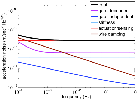
Figure, 1 provides a rough breakdown of the contributions to acceleration noise for GRACE like accelerometers. Table 1 provides the key parameters used to produce Figure 1 following the methodology outlined in [16]. The acceleration noise budget for GRACE-like accelerometers is limited by measurement and actuation noise as previously stated. If we assume a relative stability of the voltage reference of , and a nominal drag-induced acceleration of , then the suspension force noise acting on the test mass is . Here, the measurement noise is assumed to be the same.
| Parameter | GRACE-like accelerometer [5] | DMA for Earth geodesy |
|---|---|---|
| Mass of TM | 72 g | 243 g |
| TM/housing gap | 175 m | 1 mm |
| Surface area of TM | ||
| Charge control | Au wire | UV photoemission |
| Surface area of spacecraft | ||
| Mass of spacecraft | 100 kg | 100 kg |
| Magnetic susceptibility of TM | ||
| TM stray voltage | 100 mV | 100 mV |
| Max. TM charge | e | e |
| Max. dc magnetic field | 50 T | 50 T |
| Max. magnetic field fluctuation | 1 | 1 |
| Max. magnetic field gradient | 10 T/m | 10 T/m |
| Max. field gradient fluctuations | 0.25 | 0.25 |
| Pressure inside housing | 10 Pa | 10 Pa |
| Temperature difference | (1mHz/)(1/3) | (1mHz/)(1/3) |
| fluctuations across housing |
In Figure 1 there is one additional noise source related to controlling the buildup of charge on the test mass. These accelerometers use an extremely thin diameter) gold fiber to electrically ground the test mass to its electrode housing. This wire contributes a thermal force noise on the test mass with a spectrum.
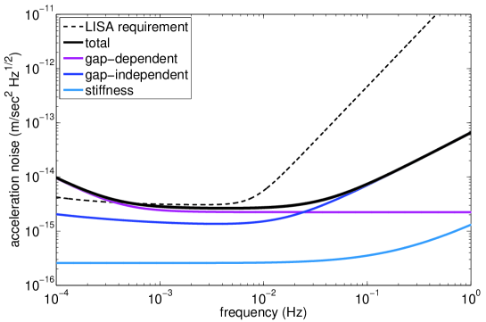
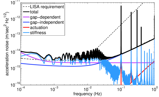
Figure 2 shows the approximate acceleration noise budget for LISA, with individual noise terms grouped as before. This budget follows that of [15, 16]. Also shown in Figure 2 is the requirement for LISA, from roughly 0.1 - 10 mHz. Since LISA is operated ’true’ drag-free mode there is no test mass actuation and therefore no associated acceleration noise. Two other factors that greatly improve the performance of the LISA GRS relative to GRACE are larger gaps (10 that of GRACE), and a non-contact charge control system, based on photoemission using UV light [17]. The second difference eliminates the thermal noise of the gold fiber used in the GRACE accelerometers.
2.1 A drift mode accelerometer model
In order to estimate the acceleration noise performance of a drift mode accelerometer the following model, depicted in Figure 3 is used. In this model two test masses are widely separated. Test mass 2 (TM 2) is assumed to be inertially fixed for simplicity. The goal of the DMA is measure the inertial acceleration of the spacecraft which houses test mass 1 (TM 1). Measurement of the spacecraft’s motion relative the TM 1 is made relative to a optical bench (OB), which is assumed to contain two laser interferometers. The first measures the position of TM 1 relative to OB, , and the second measures OB relative to TM 2, .
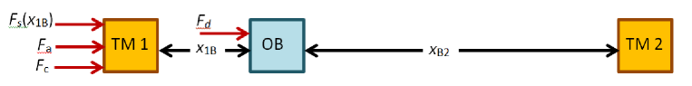
Three forces act on the TM 2: control forces denoted , position-dependent forces (stiffness forces) denoted , and all other disturbance forces . The force consists of both gap-dependent and gap-independent forces described above. The disturbance force applied to the spacecraft is denoted and is largely due to atmospheric drag in the case of Earth geodesy missions and solar radiation pressure for deep space gravitational wave and other fundamental physics missions.
A simple PID control law is implemented to keep TM 1 centered in its housing . The controller was cycled on and off with a periodicity of seconds with a duty cycle of 0.1. The disturbance force applied to the spacecraft is mission dependent and therefore Earth geodesy and gravitational wave applications were analyzed separately. The results are described below.
2.2 DMA for Earth geodesy
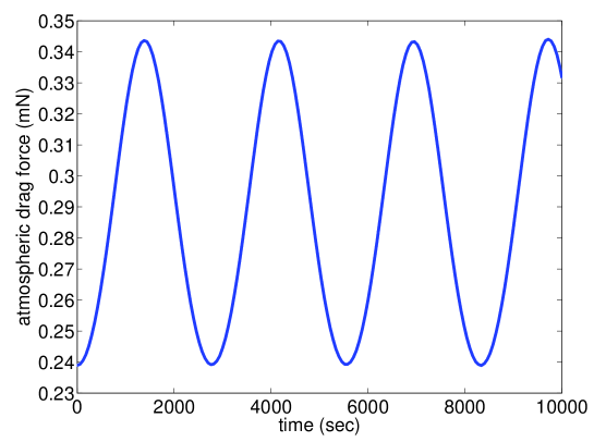
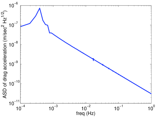
For the simulation of a low Earth orbiting satellite, atmospheric drag is calculated using the NRLMSISE-00 empirical atmospheric model acting on the spacecraft in a 400 km circular polar orbit. The spacecraft mass and cross sectional area is 100 kg and 1 respectively, and its coefficient of drag is . Figure, 4 shows the time history of the atmospheric drag force acting on the satellite and Figure 5 shows the spectrum of the corresponding drag acceleration. The main variations in the drag force occur at twice the orbital frequency.
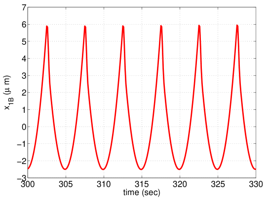
An actuation cycling period of is chosen and the resulting position time history of TM 1 relative to the spacecraft () is shown in Figure 6. Parabolic trajectories with a frequency of 0.2 Hz and an amplitude of are apparent.
To calculate the acceleration noise performance of a drift mode accelerometer designed for Earth geodesy, a candidate instrument is chosen with basic properties listed in Table 1. All key design features of the DMA are kept the same as that of the GRACE-like accelerometer, expect the size and mass of the test mass are increased to 30 cm and 243 g respectively, and a TM-to-housing gap size of 1 mm is used. In addition, it is assumed that the gold wire used for test mass charge control is eliminated and replaced with a charge control system utilizing UV photoemission. Figure 7 shows the estimated performance of such an instrument. Gap-dependent and gap-independent acceleration noise terms are calculated as before. Actuation noise is modeled simply as the spectrum of maximum applied acceleration multiplied by a relative voltage noise of , with a 0.1 duty cycle a repetition rate of 1/5 sec. In reality, for a DMA the acceleration data is discarded while the actuation system is on and spacecraft acceleration is only estimated using the data when the actuation system is off. Therefore, if we assume we retrieve one acceleration measurement per actuation cycle, then the maximum frequency of the acceleration noise spectrum should be 0.2 Hz. By comparing Figures 1 and 7 we see that the broadband acceleration noise of for the traditional accelerometer is frequency shifted to 0.2 Hz plus harmonics.
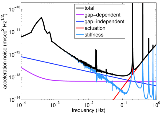
As we can see in Figure 7 the limiting acceleration noise term is stiffness, which is the coupling of the motion of the spacecraft relative to TM 1 and the stiffness, . Most of the stiffness related acceleration noise contribution occurs at the suspension cycling frequency of 0.2 Hz and its harmonics. Contributions at lower frequencies, especially twice the orbital frequency, are caused by the low frequency contribution of the atmospheric drag. As discussed below, if the stiffness can be be determined through calibration, then the stiffness-related acceleration noise can be subtracted in the data analysis. The resulting acceleration noise of the DMA for Earth geodesy would then be around 1 mHz.
2.3 DMA for gravitational wave observation
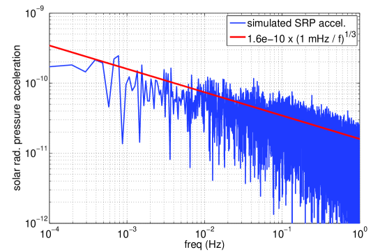
In order to assess the performance of the DMA for with respect to gravitational wave observation, the geometry and other properties of the accelerometer were assumed to be the same as the LISA Pathfinder gravitational reference sensor. The LPF GRS is a 2 kg, 46 mm, Au/Pt cube, with 4 mm gaps along the sensitive axis between the test mass and its electrode housing. For a 500 kg spacecraft at a distance of 1 AU from the Sun, the zero-frequency spacecraft acceleration due to solar radiation pressure is,
The high frequency solar radiation pressure, taken from [15] is, . Solar radiation pressure acceleration amplitude spectral density and the spectrum of the numerically simulated acceleration are shown in Figure 8.
If the suspension system is operated with a repetition rate of 0.1 Hz and a duty cycle of 0.1, the resulting parabolic motion of TM 1 relative to the optical bench has an amplitude on the order of 250 as shown in Figure 9.
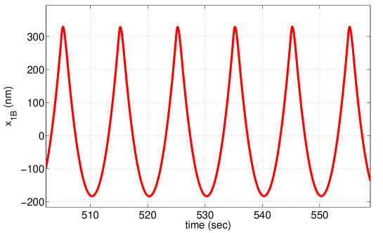
Figure 10 shows the resulting performance of the DMA with respect to gravitational wave observation. As is the case for the Earth geodesy DMA, the limiting acceleration noise term is stiffness, which again is the coupling of the motion of the spacecraft relative to TM 1 and the stiffness, . Most of the stiffness related acceleration noise contribution occurs at the suspension cycling frequency of 0.1 Hz and its harmonics. Contributions at lower frequencies are caused by the low frequency contribution of the solar radiation pressure acceleration noise acting on the satellite. As with the geodesy application, if the stiffness can be determined through calibration, then the stiffness-related acceleration noise can be subtracted in the data analysis.
In both applications there exist at least two acceleration noise sources that may be calibrated and removed in the data analysis. They are stiffness (position-dependent) forces and actuation cross-coupling forces. Both are not fundamentally limiting (e.g. unavoidable quantum mechanical effects) and can therefore be calibrated and removed. However, a rigorous determination of the possible accuracy of such a calibration must still be determined.
2.4 Position-dependent noise
Because of the increased motion of the test mass relative to its housing the stiffness related force noise is much larger than that of the GRACE accelerometers or the drag-free LISA GRS. These position dependent forces do not represent a fundamental limit to the performance of the DMA. If stiffness can be determined through calibration, then the measured position of TM 1 relative to the spacecraft can be used to estimate and subtract it in the data analysis. Procedures for estimating the stiffness to high precision have been developed for LISA Pathfinder [18], though these techniques rely on measuring the motion of one test mass relative to another. Determination of for the DMA might therefore require measurement of position of TM 1 relative to TM 2 (), which is of course readily available. The stiffness related signal present in would be primarily at the kicking frequency, which is chosen to be above the dominant science signals of interest. Therefore, estimation of from these data should be cleaning separable from the science signal.
In order for position-dependent acceleration noise to be reduced below the fundamental limit of around 1 mHz for the Earth geodesy DMA, the stiffness must be determined with a relative accuracy of 0.1 or an absolute accuracy of . For the gravitational wave DMA the stiffness is much lower () because of the increased gap size, the larger test mass, and the stricter requirements on the environmental stability of the GRS. Already, the position-dependent acceleration noise, shown in Figure 10, for gravitational wave observation is near the fundamental limit. To drop it below this limit calibration accuracy must be a modest 0.2 relative to or absolute.
Of course, increasing the actuation cycling frequency reduces the spacecraft-to-TM motion and therefore reduces stiffness related acceleration noise. One could therefore choose a cycling frequency that is high enough to reduce the stiffness related acceleration noise to below the fundamental limit. However, as we will see in Section 3, reducing the actuation cycling frequency dramatically increases the interferometric acceleration measurement noise.
2.5 Actuation cross-coupling
Two different methods can be used to suspend the test mass in all rotational degrees of freedom and in all translational degrees of freedom orthogonal to the sensitive direction. These degrees of freedom can either be continuously supported or operated in drift mode just like the sensitive degree of freedom. All degrees of freedom can be operated in drift mode only if the resulting motion does not cause loss of performance of the interferometer, which measures displacement along the sensitive axis. This generally requires a relatively high cycling frequency, which again results in a relatively large acceleration measurement noise as discussed in Section 3.
If we assume that all degrees of freedom except the degree of freedom along the sensitive axis are suspended continuously against the external forces applied to the host spacecraft, then we must consider the additional acceleration noise acting in the sensitive direction due to actuation cross-coupling. Actuation cross-coupling is the inadvertent forcing of the test mass in the sensitive direction, which occurs when actuating the test mass in another degree of freedom due to a small residual coupling . This cross coupling can be as large as for inertial sensors like that of LISA. For both geodesy and gravitational wave applications, this cross coupling acceleration exceeds the fundamental acceleration noise limit in the sensitive direction.
If these cross coupling coefficients can be determined, then using the known applied forces in all degrees of freedom, the resulting force in the sensitive direction can be calculated or eliminated with the appropriate combination of applied electrode voltages. Determination of such coefficients has been precisely demonstrated by the GOCE mission and will also be performed during the LISA Pathfinder mission [18].
One technique for determining these cross-coupling coefficients is to dither the actuation voltages in each of the non-sensitive degrees of freedom and fit a model of the cross-coupling to the interferometric measurement of the test mass motion along the sensitive axis. To roughly determine how well the cross coupling coefficient can be determined using this approach, the numerical simulation described above was modified to include a dither voltage equivalent to a test mass acceleration of on a perpendicular axis with a frequency of 10 mHz. For a sec simulation, the interferometer readout along the sensitive axis with an assumed measurement noise of was capable of estimating with a relative accuracy of .
Examining Figure 5 we see that the atmospheric drag acceleration at 1 mHz is . If we assume a cross coupling coefficient of and a desired acceleration noise of , then we must determine to a relative accuracy of 0.003 for the Earth geodesy DMA. Likewise, from Figure 8, the solar radiation pressure acceleration noise around 1 mHz is . Again, using and a desired acceleration noise of , we must determine also to a relative accuracy of 0.003 for the gravitational wave DMA.
There does exist a fundamental limit to how well these cross-coupling forces can be determined and subtracted in the analysis. We assume that the best possible voltage reference is limited to a relative voltage stability of . For the geodesy application it is reasonable to assume that maximum cross-track acceleration, which occurs with a polar Earth orbit is . Therefore, it is also reasonable to assume that the maximum dynamic range of the cross track suspension force results in an acceleration that is ten times this value, or . Finally, assuming a cross coupling coefficient of , resulting acceleration in the along track (sensitive direction) is,
which is below the fundamental limit shown in Figure 7.
For the the gravitational wave application, again we assume the a 500 kg LISA-like spacecraft, with cross sectional area of is 1 AU from the Sun. The resulting nominal solar radiation pressure is . Therefore, if we assume that the maximum required test mass suspension force is , the fundamental cross-coupling acceleration noise limit is,
which is roughly equal to the LISA acceleration noise requirement at low frequency.
3 Measurement noise
In a DMA we use a laser interferometer to measure the acceleration of a reference point on the spacecraft (an optical bench) relative to the test mass, which we assume is inertially fixed. Therefore, in addition to the acceleration noise acting on the TM, we must also consider the acceleration measurement noise of the interferometer. For the discussions here, we will assume that the interferometer exhibits a flat amplitude spectral density. We analyze the position measurement provided by the interferometer between kicks to estimate the acceleration of the spacecraft. There are several approaches that can be used, including second order finite differencing. One of the best approaches is to fit a parabola to the sampled position data between kicks. We fit the following model to the measured data :
| (2) |
The fit parameters are , the mean position, , the mean velocity, and , the mean acceleration, which is what we wish to estimate. This approach, which has the advantage of being linear and using all of the measured data, provides one acceleration measurement per kick period, . The resulting acceleration measurement noise (standard deviation), , depends linearly on the interferometer noise level , quadratically on , and inversely on the square root of the number of samples, . If we assume a constant sampling frequency, say 10 Hz, and a small but constant duty cycle, say 0.1, then the number of samples is roughly proportional to . We then have the following relationship between acceleration measurement noise, interferometer noise and kick period:
| (3) |
The parameter , of order 1, depends on the cross correlation between the mean acceleration and the constant and linear terms and . Larger kick periods greatly decrease the acceleration measurement noise, but also greatly increase the maximum displacement of the test mass relative to its housing. Larger kick periods also proportionally reduce the bandwidth of the measurement since one acceleration noise measurement is made every .
Assuming that the interferometer exhibits a white noise spectrum in displacement, then the acceleration measurement noise also has a white spectrum (a linear function of a Gaussian is a Gaussian). This is one disadvantage of the DMA since the measurement noise spectrum is flat in acceleration, while a continuous test mass displacement measurement, uninterrupted by kicks (e.g. using drag-free), which is then twice differentiated has a spectrum in acceleration. Therefore, the measurement noise in acceleration for a drag-free systems is much lower at lower frequencies where most of the interesting science is, assuming a given interferometer noise level.
Figure 11 plots the relationship between acceleration measurement noise and interferometer noise for , and . The estimated acceleration measurement noise calculated using the standard covariance analysis is shown in blue, while red curves show the measurement error obtain through a numerical simulation. The simulation assumed a spacecraft acceleration due to the solar radiation pressure model discussed above, a 0.1 duty cycle, and a sampling rate of 10 Hz. The interferometer (IFO) noise was assumed to be white with a standard deviation as shown on the plot after averaging over 1 sec (10 samples). We see from Figure 11 that the solar radiation pressure noise at high frequencies does not adversely affect the acceleration measurement. For a desired acceleration measurement noise of and a kicking period of 10 sec an interferometer with a white noise level of 40 is needed. For a 50 sec kicking period a 2 interferometer is needed.
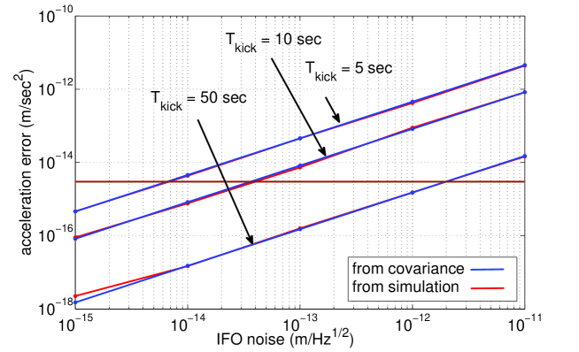
These interferometer requirements only apply to the local (short-arm) interferometer, which is far from being shot noise limited, and not the intra-spacecraft (long-arm) interferometer. In addition, these noise requirements only apply at frequencies above in the case . Therefore, we need not worry about challenging low frequency measurement noise, for example due to temperature changes and thermal expansion or index of refraction changes of materials. Each short-arm interferometer measurement lasting seconds is independent of all others.
4 DMA electrode geometry
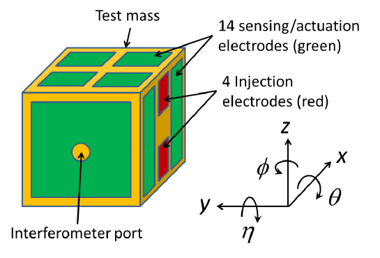
Figure 12 shows a proposed electrode geometry that is slightly modified from that of the LISA Pathfinder GRS [19]. The geometry shown in Figure 12 maximizes the actuation authority along the sensitive -axis and at the same time decouples -axis actuation from that of all other degrees of freedom. This allows a clean separation of drift-mode operation along and continuous suspension in all other degrees of freedom. A small port is needed in the middle of the -axis electrode to allow for the interferometric readout along . Mechanical pins required to cage the test mass during launch would be located between the two injection electrodes along the -axis.
5 Testing drift mode accelerometry
Precision torsion pendula thus far represent the best method of testing the performance of precision inertial instruments in the laboratory [20]. One such pendulum at the University of Florida consists of a cross bar supported by a 1 m long, 50 diameter W fiber. A light-weighted aluminum cubic test mass is mounted at each of the four ends of the cross bar. Two electrode housings surround two opposing test masses. The cross bar is used to convert the rotational motion of the torsion pendulum into mostly translational motion of the four test masses. The electrode housings can both electrostatically force the test masses and readout their position capacitively. A small port is also incorporated into the electrode housings to allow for an interferometric readout of the test mass’ position. The entire apparatus is housed in a vacuum chamber.
In order to test the performance of the DMA, the neutral orientation of the pendulum can be biased so that the pendulum restoring force can be made equivalent to the dc acceleration of the spacecraft either due to atmospheric drag or solar radiation pressure. The electrostatic actuation system can be operated with a low duty cycle just as described above and a laser interferometer can be used to estimate the test mass’ acceleration. higher frequency spacecraft disturbances can be simulated by varying the neutral orientation of the pendulum or by applying noise voltages to the electrodes that are equivalent to the spacecraft acceleration noise. With this approach the acceleration noise floor can be measured and compared with the acceleration noise floor obtained with the actuation turned off and the pendulum in its neutral orientation set with the test masses centered in their housings.
The best way to determining the performance of the DMA would be to test the instrument in space. The LISA Pathfinder mission offers one opportunity to do this. If the drag-free and micropropulsion systems were turned off and both test masses were operated in a drift mode, then the resulting differential acceleration noise between the two test masses could be estimated using the on-board laser interferometer. All cross couplings and stiffness can be determined and accounted for in the analysis of the data.
6 Conclusion
The drift mode accelerometer is a modified electrostatic accelerometer potentially capable of acceleration noise performance similar to that of drag-free systems without the need for drag-free control or associated precision propulsion. A DMA consists of a dense test mass that is freely floating inside an electrode housing, which can both sense its position capacitively and actuate it electrostatically. Unlike traditional electrostatic accelerometers, the suspension system is operated with a low duty cycle and with a cycling frequency that is chosen to be above the science signals of interest. Measurement of spacecraft acceleration is made using a laser interferometer, which is not limited by dynamic range. Two applications of the DMA, Earth geodesy and gravitational wave observation, are studied. Both represent gravitational science missions where the DMA might be used to replace drag-free operation. For gravitational wave observation, the combination of the existing LISA Pathfinder gravitational reference sensor and the LISA local (short-arm) interferometer can be operated as a drift mode accelerometer, with acceleration noise performance close to that required for LISA. Detailed modeling and analysis is still required to fully determine the acceleration noise performance and instrument requirements and constraints. Laboratory testing using torsion pendula provide one promising approach for demonstrating the performance and operation of the drift mode accelerometer.
7 Acknowledgments
The author would like to thank Guido Müller and Giacomo Ciani at the University of Florida and William Weber at the University of Trento for their valuable insights related to this work.
References
- [1] B. D. Tapley, S. Bettadpur, M. Watkins and C. Reigber, Geophys. Res. Lett. 31 9607-+, (2004).
- [2] P. Touboul, M. Rodrigues, G. M´etris, B. Tatry. Microscope C. R. Acad. Sci. IV 2 1271 – 86, (2001).
- [3] Everitt C. W. F., D. B. DeBra, et al. Gravity Probe B: Final Results of a Space Experiment to Test General Relativity. Phys. Rev. Lett., 106, 221101-1—221101-4, (2011).
- [4] M. Armano M, et al. Class. Quantum Grav. 26 1 – 18, (2009).
- [5] P. Touboul, B. Foulon, B. Christophe, J. P. Marque. CHAMP, GRACE, GOCE Instruments and Beyond Geodesy for Planet Earth, International Association of Geodesy Symposia 136, pp 215-221, (2012).
- [6] M. R. Drinkwater, R. Floberghagen, R. Haagmans, D. Muzi, A.Popescu. GOCE: ESA’s First Earth Explorer Core Mission Earth Gravity Field from Space — From Sensors to Earth Sciences Space Sciences Series of ISSI, 17, pp 419-432, (2003).
- [7] B. Christophe, J. P. Marque, B. Foulon. In-orbit Data Verification of the Accelerometers of the ESA GOCE Mission. Société Francaise d’Astronomie et d’Astrophysique (SF2A), (2010).
- [8] B. Lange, The Drag-free Satellite, AIAA Journal, 2(9), 1590-1606, (1964).
- [9] D. B. DeBra, J. W. Conklin. Measurement of drag and its cancellation. Class. Quantum Grav. 28 094015, (2011).
- [10] W. J. Bencze, C. B. DeBra, L. Herman, T. Holmes, M. Adams, G. M. Keiser, C. w. f. Everitt. . Proc. 29th AAS Guidance and Control Conf. ed S D Jolly and R D Culp (San Diego, CA: Univelt Inc.) 624, (2006).
- [11] 1974 Staff of the space department of the John Hopkins University Applied Physics Lab and the staff of the guidance and control laboratory of Stanford University. J. Spacecr. Rockets 11 637–+.
- [12] 1973 APL Technical Digest, 12 2–39
- [13] M. Armano, et al. LISA Pathfinder: the experiment and the route to LISA Classical and Quantum Gravity, 26(9), 094001, (2009).
- [14] A. Grynagier, W. Fichter, S. Vitale. The LISA Pathfinder drift mode: implementation solutions for a robust algorithm. Classical and Quantum Gravity, 26(9), 094007, (2009).
- [15] B. Schumaker. Disturbance reduction requirements for LSIA. ClasA new torsion pendulum for testing the limits of free-fall for LISA test massessical and Quantum Gravity, 20, S239-S253, (2003).
- [16] D. Gerardi, G. Allen, J.W. Conklin, K-X. Sun, D. DeBra, S. Buchman, P. Gath, W. Fichter, R.L. Byer, U. Johann. Invited Article: Advanced drag-free concepts for future space-based interferometers: acceleration noise performance. Rev. Sci. Instrum. 85, 011301 (2014).
- [17] D. N. A. Shaul, H. M. Araújo, G. K. Rochester, M. Schulte, T. J. Sumner. Charge Management for LISA and LISA Pathfinder. International Journal of Modern Physics D, 17(7) 993-1003 (2008).
- [18] F. Antonucci, et al. LISA Pathfinder data analysis. Class. Quantum Grav., 28, 094006 (17pp), (2011).
- [19] F. Antonucci, A. Cavalleri, R. Dolesi, M. Hueller, D. Nicolodi, H.B. Tu, S. Vitale, W.J. Weber. Interaction between Stray Electrostatic Fields and a Charged Free-Falling Test Mass. Phys. Rev. Lett., 108, 181101 (2012).
- [20] A. Cavalleri, G. Ciani, R. Dolesi, A. Heptonstall, M. Hueller, D. Nicolodi, S. Rowan, D. Tombolato, S. Vitale, P. J. Wass, W. J. Weber. A new torsion pendulum for testing the limits of free-fall for LISA test masses. Classical and Quantum Gravity, 26(9), 094017 (2009).