All-optical controlled phase gate in quantum dot molecules

Li-Bo Chen1 and Wen Yang2 1 School of Science, Qingdao Technological University, Qingdao 266033, China 2 Beijing Computational Science Research Center, No.3 Heqing Road Haidian District Beijing 100084, China wenyang@csrc.ac.cn
Abstract

We propose a two-qubit optically controlled phase gate in quantum dot molecules via adiabatic passage and hole tunneling. Our proposal combines the merits of the current generation of vertically stacked self-assembled InAs quantum dots and adiabatic passage. The simulation shows an implementation of the gate with a fidelity exceeding 0.98.

pacs:
78.67.Hc, 03.67.Lx

1 Introduction

The spin of an electron, trapped in a self-assembled semiconductor quantum dot (SAQD) and manipulated by laser pulses, is believed to be a promising qubit candidate for quantum computation and quantum communication. Such qubits can be optically controlled in high speed [1, 2] and its coherence times has been prolonged to the order of microseconds [3]. Recently, there have been many experimental demonstrations of the key DiVincenzo requirements [4] for such qubit, for examples, spin initialization [5, 6, 7], the coherent manipulation of electron spins [1, 2], and fast spin nondestructive measurement [8].

Entangling gates for two qubits form an essential ingredient of quantum computation. Significant effort has been invested in theoretical protocols for two qubit gate [9, 10, 11, 12, 13, 14, 15, 16, 17] and experimental demonstration of optical entanglement control [18] between QDs. However there has been no reported experimental realization of optically controlled phase gate between QDs. In this paper, we propose a two-qubit controlled phase gate in a vertical self-assembled quantum dot molecule (SAQDM) [19, 20] utilizing adiabatic passage and hole tunneling. Compared with our previous scheme [16], the using of adiabatic passage efficiently suppressing spontaneous decay from excited states [21, 22, 23, 24, 25, 26] and need not precisely timing the interval between the two pulses. Our proposal bases on the current generation of SAQDMs, and the simulation shows the gate can implemented with a fidelity exceeding 0.980.980.98.

2 The Basic model

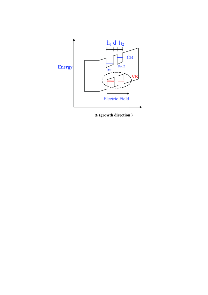
Our model is based on the vertically coupled SAQDs [19] (see Fig. 1). The electrons or holes can tunnel between the two dots to create a quantum dot molecule (QDM). For the QDMs discussed here, the nominal height of dot 111, h1subscriptβ„Ž1h_{1}, is greater than that of do t 222, h2subscriptβ„Ž2h_{2}, so that dot 111 exhibits the lower transition energy. This allows the hole levels to be brought into resonance with a positive electric field applied along the xπ‘₯x axis (the growth direction), while the electron level of dot 222 is shifted to a much higher energy than that of dot 111. We use the spin of the electrons in each dot as the qubits. In the Faraday geometry, the energy levels for the single QD system in the presence of a small magnetic field Bzsubscript𝐡𝑧B_{z} along the z𝑧z axis (perpendicular to the xπ‘₯x axis) [7, 27]. The two eigenstate states of electron spin, i.e. |β†‘βŸ©ket↑\left|\uparrow\right\rangle and |β†“βŸ©ket↓\left|\downarrow\right\rangle, are split by the magnetic field Bzsubscript𝐡𝑧B_{z}. The lowest-energy interband transition is to the trion state |β†‘β†“β‡‘βŸ©\left|\uparrow\downarrow\Uparrow\right\rangle (|β†“β†‘β‡“βŸ©\left|\downarrow\uparrow\Downarrow\right\rangle), consisting of two electrons in a singlet state and a heavy hole. Optical selection dictate that the Οƒβˆ’superscript𝜎\sigma^{-} (Οƒ+superscript𝜎\sigma^{+}) polarization laser could coupled the transition |β†“βŸ©β†’|β†“β†‘β‡“βŸ©\left|\downarrow\right\rangle\rightarrow\left|\downarrow\uparrow\Downarrow\right\rangle (|β†‘βŸ©ket↑\left|\uparrow\right\rangle β†’|β†‘β†“β‡‘βŸ©\rightarrow\left|\uparrow\downarrow\Uparrow\right\rangle) , and other transitions are forbidden.

3 Implementation of two qubits phase gate

The ideal phase gate aims to impose a phase change on the state |↑,β†“βŸ©ket↑↓\left|\uparrow,\downarrow\right\rangle without affecting the phase of the other three states. It should also preserve phase coherence for a superposition of the four QD spin states. This operation can be characterized by the unitary transformation:

|↑,β†‘βŸ©ket↑↑\displaystyle\left|\uparrow,\uparrow\right\rangle β†’β†’\displaystyle\rightarrow |↑,β†‘βŸ©,|↑,β†“βŸ©β†’βˆ’|↑,β†“βŸ©,β†’ket↑↑ket↑↓ket↑↓\displaystyle\left|\uparrow,\uparrow\right\rangle\ ,\left|\uparrow,\downarrow\right\rangle\rightarrow-\left|\uparrow,\downarrow\right\rangle,\,
|↓,β†‘βŸ©ket↓↑\displaystyle\left|\downarrow,\uparrow\right\rangle β†’β†’\displaystyle\rightarrow |↓,β†‘βŸ©,|↓,β†“βŸ©β†’|↓,β†“βŸ©.β†’ket↓↑ket↓↓ket↓↓\displaystyle\left|\downarrow,\uparrow\right\rangle,\left|\downarrow,\downarrow\right\rangle\rightarrow\left|\downarrow,\downarrow\right\rangle. (1)

We use the convention that the vertical arrows on the left and right of the comma sign are, respectively, the directions of the spins in dot 111 and dot 222.

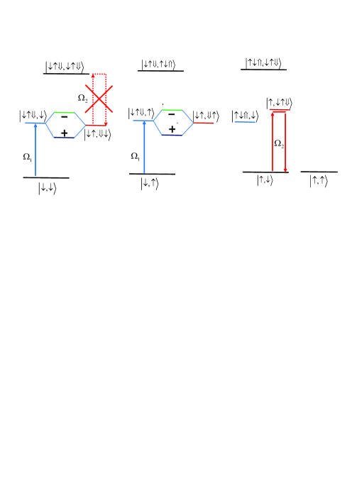
Fig. 2 shows the the level diagram of the two quantum dot and gate operation process, which includes three sequential steps:

Firstly, the QDM is illuminated with a Οƒβˆ’superscript𝜎\sigma^{-} circularly polarized continuous wave (CW) laser Ξ©1​(t)subscriptΞ©1𝑑\Omega_{1}\left(t\right) propagating in the xπ‘₯x direction. The laser is tuned such that it could create an exciton in the quantum dot 111 (only if it is state is |β†“βŸ©ket↓\left|\downarrow\right\rangle) without affecting the quantum dot 222. The Hamiltonian for the QDM under this laser excitation is

H1=Ξ©1(t)|↓↑⇓,↓(↑)βŸ©βŸ¨β†“,↓(↑)|+Ο„|↓↑,⇓↓(↑)βŸ©βŸ¨β†“β†‘β‡“,↓(↑)|+H.c.,\begin{array}[]{ccc}H_{1}=&\Omega_{1}\left(t\right)\left|\downarrow\uparrow\Downarrow,\downarrow(\uparrow)\right\rangle\left\langle\downarrow,\downarrow(\uparrow)\right|&\\ &+\tau\left|\downarrow\uparrow,\Downarrow\downarrow(\uparrow)\right\rangle\left\langle\downarrow\uparrow\Downarrow,\downarrow(\uparrow)\right|+H.c.,&\end{array} (2)

where we assume ℏ=1Planck-constant-over-2-pi1\hbar=1, and Ο„πœ\tau is the hole tunneling rate between the two dots. The Hamiltonian has a dark state

|DβŸ©βˆΟ„|↓,↓(↑)βŸ©βˆ’Ξ©1(t)|↓↑,⇓↓(↑)⟩.\left|D\right\rangle\varpropto\tau\left|\downarrow,\downarrow(\uparrow)\right\rangle-\Omega_{1}\left(t\right)\left|\downarrow\uparrow,\Downarrow\downarrow(\uparrow)\right\rangle.\, (3)

If we turn on the Οƒβˆ’superscript𝜎\sigma^{-} circularly polarized laser and increase the Ξ©1​(t)subscriptΞ©1𝑑\Omega_{1}\left(t\right) slowly, when Ξ©1​(t)≫τmuch-greater-thansubscriptΞ©1π‘‘πœ\Omega_{1}\left(t\right)\gg\tau the state |↓,↓(↑)⟩\left|\downarrow,\downarrow(\uparrow)\right\rangle will be adiabatically transferred to the state |↓↑,⇓↓(↑)⟩\left|\downarrow\uparrow,\Downarrow\downarrow(\uparrow)\right\rangle almost without exciting the media state |↓↑⇓,↓(↑)⟩\left|\downarrow\uparrow\Downarrow,\downarrow(\uparrow)\right\rangle. In this process, the states |↑,β†‘βŸ©ket↑↑\left|\uparrow,\uparrow\right\rangle and |↑,β†“βŸ©ket↑↓\left|\uparrow,\downarrow\right\rangle are not affected by the CW laser Ξ©1subscriptΞ©1\Omega_{1}.

Secondly, we apply a Οƒβˆ’superscript𝜎\sigma^{-} circularly polarized pulse Ξ©2subscriptΞ©2\Omega_{2} to coupled the state |↑,β†“βŸ©ket↑↓\left|\uparrow,\downarrow\right\rangle to the state |↑,β†“β†‘β‡“βŸ©\left|\uparrow,\downarrow\uparrow\Downarrow\right\rangle. The Hamiltonian for the QDM under this laser excitation is

H2=Ξ©2(t)|↑,β†“β†‘β‡“βŸ©βŸ¨β†‘,↓|+Ο„|↑⇓,β†“β†‘βŸ©βŸ¨β†‘,↓↑⇓|+H.c..H_{2}=\Omega_{2}\left(t\right)\left|\uparrow,\downarrow\uparrow\Downarrow\right\rangle\left\langle\uparrow,\downarrow\right|+\tau\left|\uparrow\Downarrow,\downarrow\uparrow\right\rangle\left\langle\uparrow,\downarrow\uparrow\Downarrow\right|+H.c.. (4)

Starting with the initial state |↑,β†“βŸ©ket↑↓\left|\uparrow,\downarrow\right\rangle the system evolves at the time t𝑑t to

|Οˆβ€‹(t)⟩=1Ο„2+Ξ©22(Ο„2+Ξ©22cos(tΟ„2+Ξ©22)|↑,β†“βŸ©βˆ’iΞ©2Ο„2+Ξ©22sin(tΟ„2+Ξ©22)|↑,β†“β†‘β‡“βŸ©+(τΩ2cos(tΟ„2+Ξ©22)βˆ’Ο„Ξ©2)|↑⇓,β†“β†‘βŸ©).\begin{array}[]{ccc}\left|\psi\left(t\right)\right\rangle=&\frac{1}{\tau^{2}+\Omega_{2}^{2}}(\tau^{2}+\Omega_{2}^{2}\cos\left(t\sqrt{\tau^{2}+\Omega_{2}^{2}}\right)\left|\uparrow,\downarrow\right\rangle&\\ &-i\Omega_{2}\sqrt{\tau^{2}+\Omega_{2}^{2}}\sin\left(t\sqrt{\tau^{2}+\Omega_{2}^{2}}\right)\left|\uparrow,\downarrow\uparrow\Downarrow\right\rangle&\\ &+\left(\tau\Omega_{2}\cos\left(t\sqrt{\tau^{2}+\Omega_{2}^{2}}\right)-\tau\Omega_{2}\right)\left|\uparrow\Downarrow,\downarrow\uparrow\right\rangle).&\end{array} (5)

At t1​τ2+Ξ©22=Ο€subscript𝑑1superscript𝜏2superscriptsubscriptΞ©22πœ‹t_{1}\sqrt{\tau^{2}+\Omega_{2}^{2}}=\pi, |ψ(t1)⟩=Ο„2βˆ’Ξ©22Ο„2+Ξ©22|↑,β†“βŸ©βˆ’2​τ​Ω2Ο„2+Ξ©22|↑⇓,β†“β†‘βŸ©\left|\psi\left(t_{1}\right)\right\rangle=\frac{\tau^{2}-\Omega_{2}^{2}}{\tau^{2}+\Omega_{2}^{2}}\left|\uparrow,\downarrow\right\rangle-\frac{2\tau\Omega_{2}}{\tau^{2}+\Omega_{2}^{2}}\left|\uparrow\Downarrow,\downarrow\uparrow\right\rangle. In the case Ξ©2≫τmuch-greater-thansubscriptΞ©2𝜏\Omega_{2}\gg\tau, t1β‰ˆΟ€/Ξ©2subscript𝑑1πœ‹subscriptΞ©2t_{1}\approx\pi/\Omega_{2}, |Οˆβ€‹(t1)βŸ©β‰ˆβˆ’|↑,β†“βŸ©ketπœ“subscript𝑑1ket↑↓\left|\psi\left(t_{1}\right)\right\rangle\approx-\left|\uparrow,\downarrow\right\rangle. The state |↑,β†“βŸ©ket↑↓\left|\uparrow,\downarrow\right\rangle acquiring a Ο€πœ‹\pi phase, the transition |↓↑,β‡“β†“βŸ©β†’|↓↑,β‡“β†“β†‘β‡“βŸ©\left|\downarrow\uparrow,\Downarrow\downarrow\right\rangle\rightarrow\left|\downarrow\uparrow,\Downarrow\downarrow\uparrow\Downarrow\right\rangle is blocked because of the Pauli exclusion principle.

Finally we slowly turn off the CW laser Ξ©1subscriptΞ©1\Omega_{1} so that the state |↓↑⇓,↓(↑)⟩\left|\downarrow\uparrow\Downarrow,\downarrow(\uparrow)\right\rangle can adiabatically transfer back to the state |↓,↓(↑)⟩\left|\downarrow,\downarrow(\uparrow)\right\rangle. The system returns to its original state and only the state |↑,β†“βŸ©ket↑↓\left|\uparrow,\downarrow\right\rangle acquires the βˆ’11-1 factor, i.e., controlled phase gate.

4 Simulation and Conclusion


To simulate the system’s dynamics, we employ master equation of density matrix ρ𝜌\rho [28]

d​ρd​t=βˆ’i​[H1+H2,ρ]+L​(ρ),π‘‘πœŒπ‘‘π‘‘π‘–subscript𝐻1subscript𝐻2𝜌𝐿𝜌\frac{d\rho}{dt}=-i\left[H_{1}+H_{2},\rho\right]+L\left(\rho\right), (6)

the superoperator L𝐿L is given by

L​(ρ)=12β€‹βˆ‘i=12(2​Li​ρ​Li+βˆ’Li+​Liβ€‹Οβˆ’Οβ€‹Li+​Li),𝐿𝜌12superscriptsubscript𝑖122subscriptπΏπ‘–πœŒsuperscriptsubscript𝐿𝑖superscriptsubscript𝐿𝑖subscriptπΏπ‘–πœŒπœŒsuperscriptsubscript𝐿𝑖subscript𝐿𝑖L\left(\rho\right)=\frac{1}{2}\sum_{i=1}^{2}\left(2L_{i}\rho L_{i}^{+}-L_{i}^{+}L_{i}\rho-\rho L_{i}^{+}L_{i}\right), (7)

where Li=Ξ³i​cisubscript𝐿𝑖subscript𝛾𝑖subscript𝑐𝑖L_{i}=\sqrt{\gamma_{i}}c_{i} describes spontaneous photon decay in QD i𝑖i.

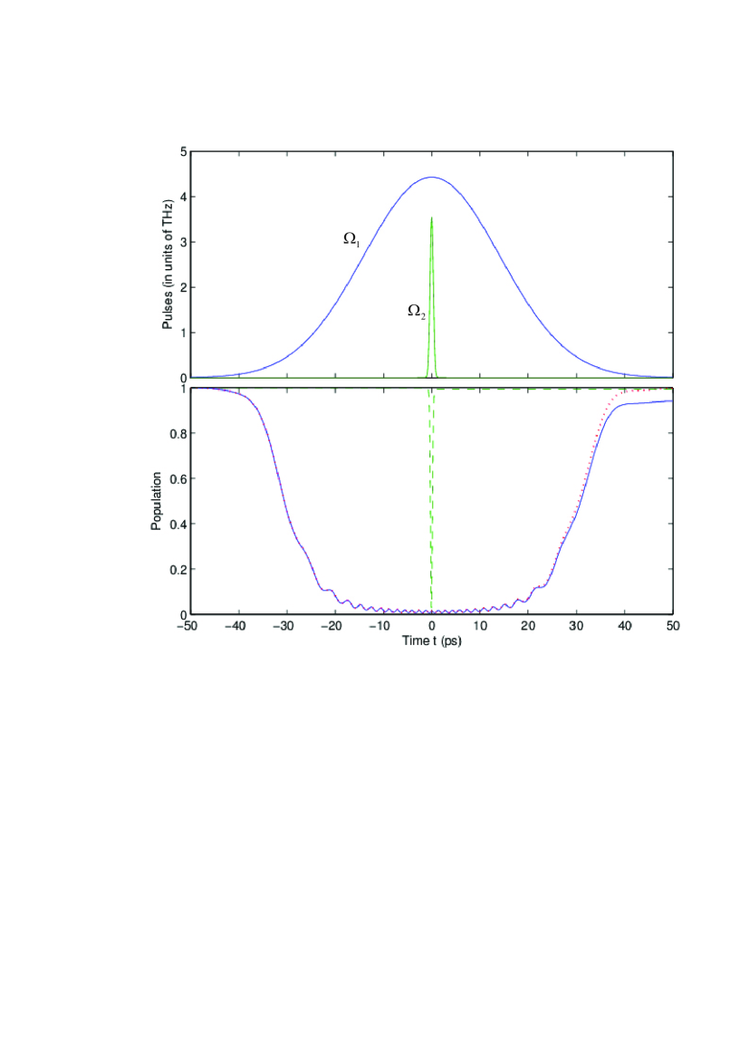
We choose the laser Rabi frequencies as Ξ©1=5​π2​t0​exp⁑[βˆ’(0.05​t)2/t02]subscriptΞ©15πœ‹2subscript𝑑0superscript0.05𝑑2superscriptsubscript𝑑02\Omega_{1}=\frac{5\sqrt{\pi}}{2t_{0}}\exp\left[-\left(0.05t\right)^{2}/t_{0}^{2}\right], Ξ©2=2​πt0​exp⁑[βˆ’(2​t)2/t02]subscriptΞ©22πœ‹subscript𝑑0superscript2𝑑2superscriptsubscript𝑑02\Omega_{2}=\frac{2\sqrt{\pi}}{t_{0}}\exp\left[-\left(2t\right)^{2}/t_{0}^{2}\right], with t0=1subscript𝑑01t_{0}=1 ps, Ο„=2𝜏2\tau=2 meV, and Ξ³1=Ξ³2=1subscript𝛾1subscript𝛾21\gamma_{1}=\gamma_{2}=1 ns-1. The dynamics of matrix elements ρ|↑,β†“βŸ©βŸ¨β†‘,↓|00\rho_{\left|\uparrow,\downarrow\right\rangle\left\langle\uparrow,\downarrow\right|}^{00}, ρ|↓,β†‘βŸ©βŸ¨β†“,↑|00\rho_{\left|\downarrow,\uparrow\right\rangle\left\langle\downarrow,\uparrow\right|}^{00}, and ρ|↓,β†“βŸ©βŸ¨β†“,↓|00\rho_{\left|\downarrow,\downarrow\right\rangle\left\langle\downarrow,\downarrow\right|}^{00}, are shown in Fig. 3, ρ|↑,β†‘βŸ©βŸ¨β†‘,↑|00\rho_{\left|\uparrow,\uparrow\right\rangle\left\langle\uparrow,\uparrow\right|}^{00} doesn’t change in this process. It shows that the time of implement the phase gate is Tgβ‰ˆ100subscript𝑇𝑔100T_{g}\approx 100 ps, if initial state |Ξ¨0⟩=12​(|↑,β†‘βŸ©+|↑,β†“βŸ©+|↓,β†‘βŸ©+|↓,β†“βŸ©)ketsuperscriptΞ¨012ket↑↑ket↑↓ket↓↑ket↓↓\left|\Psi^{0}\right\rangle=\frac{1}{2}\left(\left|\uparrow,\uparrow\right\rangle+\left|\uparrow,\downarrow\right\rangle+\left|\downarrow,\uparrow\right\rangle+\left|\downarrow,\downarrow\right\rangle\right), we calculate the fidelity of the phase gate F=0.98𝐹0.98F=0.98. The fidelity can be improved further if the lifetime of the state |↓↑,β‡“β†‘βŸ©\left|\downarrow\uparrow,\Downarrow\uparrow\right\rangle is increased. Consider this system in a cavity, the state |↓↑,β‡“β†‘βŸ©\left|\downarrow\uparrow,\Downarrow\uparrow\right\rangle will be off resonant with their cavity modes, Ξ³2subscript𝛾2\gamma_{2} can be reduced to 1.25 ns-1 [29], the fidelity can be as high as 0.9980.9980.998.

In conclusion, we have proposed an all-optical controlled phase gate which benefits from current generation of QDM and adiabatic passage. Our simulation shows the fidelity of the phase gate is exceeding 0.980.980.98 by using realistic values for all parameters.

We thanks Prof. L. J. Sham for helpful discussions. This research was supported by the National Natural Science Foundation of China (Grant No.11304174), Natural Science Foundation of Shandong Province (Grant No. ZR2013AQ010), and the research starting foundation of Qingdao.

References

  • [1] Press D, Ladd T D, Zhang B, and Yamamoto Y 2008 Nature 456 218
  • [2] Kim E D, Truex K, Xu X, Sun B, Steel D G, Bracker A S, Gammon D and Sham L J 2010 Phys. Rev. Lett. 104 167401
  • [3] Greilich, A, Yakovlev DΒ R, Shabaev A, Efros Al L, Yugova I A, Oulton R, Stavarache V, Reuter D, Wieck A, and Bayer M 2006 Science 313 341
  • [4] DiVincenzo D P 2000 Fortschr. Phys. 48 771
  • [5] Atature M, Dreiser J, Badolato A, Hogele A, Karrai K and Imamoglu A 2006 Science 312 551
  • [6] Emary C, Xu X, Steel D G, Saikin S and Sham L J 2007 Phys. Rev. Lett. 98 047401
  • [7] Xu X, Wu Y, Sun B, Huang Q, Cheng J, Steel D G, Bracker A S, Gammon D, Emary C and Sham L J 2007 Phys. Rev. Lett. 99 097401
  • [8] Kim D, Economou S E, Badescu S C, Scheibner M, Bracker A S, Bashkansky M, Reinecke T L and Gammon D 2008 Phys. Rev. Lett. 101 236804
  • [9] Piermarocchi C, Chen P, Sham L J and Steel D G 2002 Phys. Rev. Lett. 89 167402
  • [10] Calarco T, Datta A, Fedichev P, Pazy E and Zoller P 2003 Phys. Rev. A 68 012310
  • [11] Nazir A, Lovett B W, Barrett S D, Spiller T P and Briggs G A D 2004 Phys. Rev. Lett. 93 150502
  • [12] Gauger E M, Nazir A, Benjamin S C, Stace T M and Lovett B W 2008 New J. Phys. 10 073016
  • [13] Emary C and Sham L J 2007 Phys. Rev. B 75 125317
  • [14] Xu K J, Huang Y P, Moore M G and Piermarocchi C 2009 Phys. Rev. Lett. 103 037401
  • [15] Puri S, Kim N Y and Yamamoto Y 2012 Phys. Rev. B 85 241403
  • [16] Chen L B, Sham L J, Waks E 2012 Phys. Rev. B 85 115319
  • [17] Economou S E, Climente J I, Badolato A, Bracker A S, Gammon D and Doty M F 2012 Phys. Rev. B 86 085319
  • [18] Kim D, Carter S, Greilich A, Bracker A and Gammon D 2011 Nature Phys. 7 223
  • [19] Scheibner M, Doty M F, Ponomarev I V, Bracker A S, Stinaff E A, Korenev V L, Reinecke T L and Gammon D 2007 Phys. Rev. B 75 245318
  • [20] Doty M F, Climente J I, Greilich A, Yakes M, Bracker A S and Gammon D 2010 Phys. Rev. B 81 035308
  • [21] Kuklinski J R, Gaubatz U, Hioe F T and Bergmann K 1989 Phys. Rev. A 40 R6741
  • [22] Gaubatz U, Rudecki P, Schiemann S and Bergmann K 1990 J. Chem. Phys. 92 5363
  • [23] Bergmann K, Theuer H and Shore B W 1998 Rev. Mod. Phys. 70 1003
  • [24] Saikin S K, Emary C, Steel D G and Sham L J 2008 Phys. Rev. B 78 235314
  • [25] Openov L A 1999 Phys. Rev. B 60 8798
  • [26] Brandes T, Renzoni F and Blick R H 2001 Phys. Rev. B 64 035319
  • [27] Berezovsky J, Mikkelsen M H, Stoltz N G, Coldren L A and Awschalom D D 2008 Science 320 349
  • [28] Walls D F and Milburn G J 1994 Quantum Optics (Berlin: Springer-Verlag)
  • [29] Hennessy K, Badolato A, Winger M, Gerace D, AtatΓΌre M, Gulde S, FΓ€lt S, Hu E L and Imamoğlu A 2007 Nature 445 896
Refer to caption
Figure 1: Schematic of the vertically coupled quantum dot system. The height of the dot 1 is h1subscriptβ„Ž1h_{1}, that of dot 2 is h2subscriptβ„Ž2h_{2}, the interdot barrier is d𝑑d. A positive electric field along the z axis is applied to bring the hole levels into resonance.
Refer to caption
Figure 2: The energy diagram of the two Quantum dot ground states and the optically allowed transitions to the trion states. The large X indicates that the Ξ©2subscriptΞ©2\Omega_{2} pulse does not affect this transition while performing a 2​π2πœ‹2\pi rotation between |↑,β†“βŸ©ket↑↓\left|\uparrow,\downarrow\right\rangle and |↑,β†“β†‘β‡“βŸ©\left|\uparrow,\downarrow\uparrow\Downarrow\right\rangle.
Refer to caption
Figure 3: Dynamical evolution of several density matrix elements during the gate operation via numerical simulation. The top figure shows the pulse intensity of Ξ©1subscriptΞ©1\Omega_{1} and Ξ©2subscriptΞ©2\Omega_{2}. The bottom figure shows the time evolution of three density matrix elements during the controlled phase gate operation, in which the solid (blue) line, the dot (red) line, and the dash (green) line denote density matrix elements ρ|↓,β†‘βŸ©βŸ¨β†“,↑|00\rho_{\left|\downarrow,\uparrow\right\rangle\left\langle\downarrow,\uparrow\right|}^{00}, ρ|↓,β†“βŸ©βŸ¨β†“,↓|00\rho_{\left|\downarrow,\downarrow\right\rangle\left\langle\downarrow,\downarrow\right|}^{00}, and ρ|↑,β†“βŸ©βŸ¨β†‘,↓|00\rho_{\left|\uparrow,\downarrow\right\rangle\left\langle\uparrow,\downarrow\right|}^{00}. ρ|↑,β†‘βŸ©βŸ¨β†‘,↑|00\rho_{\left|\uparrow,\uparrow\right\rangle\left\langle\uparrow,\uparrow\right|}^{00} doesn’t change in this process.