W-Band Pancharatnam Half Wave Plate Based on Negative Refractive Index Metamaterials
Abstract
Electromagnetic metamaterials, made from arrangements of subwavelength sized structures, can be used to manipulate radiation. Designing metamaterials that have a positive refractive index along one axis and a negative refractive index along the orthogonal axis can result in birefringences, . The effect can be used to create wave plates with subwavelength thicknesses. Previous attempts at making wave plates in this way have resulted in very narrow usable bandwidths. In this paper, we use the Pancharatnam method to increase the usable bandwidth. A combination of Finite Element Method and Transmission Line models were used to optimise the final design. Experimental results are compared to the modelled data.
pacs:
(160.3918) Metamaterials; (350.3618) Left-handed materials; (120.5410) Polarimetry; (230.5440) Polarization-selective devices; (260.5430) Polarization; (230.0230) Optical devices.I Introduction
Electromagnetic metamaterials, periodically arranged sub-wavelength structures, can be used to interact with radiation in ways generally unattainable with natural materials. In the form of metal mesh grids, they have been used since the 1960’s by authors such as Ulrich ulrich_far-infrared_1967 to create polarisers and filters. The grids properties were based on the inductive and capacitive responses that radiation had to the grids geometries. In the past decade such grids have been rediscovered primarily for their use in producing negative refractive indices (NRI), and also for their ability to be designed with customised electromagnetic properties. This technology finds applications in the microwave and terahertz frequency ranges where the availability of suitable dielectric materials that can be used to manufacture optical components is very limited.
Most uses for NRI have focused on cases where isotropic behaviour is required e.g. in the creation of “perfect lenses” pendry_negative_2000 . However, polarisation dependent responses can be used to design birefringent metamaterials and hence wave plates. Wave plates (or retarders) are optical devices that alter the polarisation state of radiation transmitted through them. Half Wave Plates (HWPs) are a particular type of wave plate used to arbitrarily rotate the polarisation angle of linearly polarised radiation. They find application when linear polarisation modulation is required. In these cases, a HWP rotating at a frequency, , is placed in front of a linearly polarised detector. In this setup, the intensity of linearly polarised radiation reaching the detector varies with a frequency of whilst the intensity of unpolarised radiation is unaffected. This allows the detector to discriminate between radiation from polarised and unpolarised sources.
In this paper, NRI will be used in combination with positive refractive indices (PRI) to create a highly birefringent HWP. This idea has been applied in weis_strongly_2009 where the results were very narrowband. In order in to increase the bandwidth in this work the Pancharatnam method pancharatnam_achromatic_1955 ; pancharatnam_achromatic_1955-1 is employed for first time with NRI based wave plates.
II Birefringence and Half Wave Plates
A common way to design wave plates is to use uniaxial birefringent materials. Assuming a Cartesian coordinate system, a uniaxial birefringent material has refractive index values such that . Radiation propagating through these materials experience different refractive indices depending on the radiation’s initial polarisation state and propagation direction. This implies that two orthogonal polarisation components can travel at different speeds through the material causing a differential phase shift, , so altering the polarisation state from that of the incoming radiation. By cutting a slab of a uniaxial birefringent material with its entrance and exit surfaces parallel to the material’s optic axis, a wave plate is created. For a given frequency, , the value of produced by a wave plate of thickness, , is equal to
| (1) |
where is the free space speed of light and , a quantity known as the birefringence. To create a HWP, the radiation passing through it must experience a of .
In the mm-wavelength range, there are not many birefringent materials available for the manufacture of wave plates. Commonly used materials include sapphire and quartz, both of which have afsar_precision_1987 ; lamb_miscellaneous_1996 . For a fixed frequency it can be seen from equation (1) that the is proportional to . So using materials with low birefringence values leads to thicker wave plates with an increased amount of weight and absorption compared to thinner wave plates made of the same material. The weight consideration is important in cases where large diameters () are required at cryogenic temperatures.
An alternative to natural materials would be to use the aforementioned metamaterials. By designing them so that they present a PRI to one polarisation and a NRI to the orthogonal polarisation, a greater than unity can be created. This would allow the manufacturing of subwavelength thick wave plates, much thinner than those made with birefringent materials. This idea was applied in weis_strongly_2009 to produce a HWP and a QWP. The grids used in weis_strongly_2009 are similar to the capacitive grids used for mesh filters in ulrich_far-infrared_1967 . To create a NRI the grids were paired up in the radiation’s propagation direction. Resonances in the individual grids result in a negative permittivity, whilst the anti-parallel currents in the grid pair produces a current loop allowing the production of a negative permeability. When these two conditions occur in the same frequency range a NRI is produced. The resulting wave plates made in this way however had very narrow usable bandwidths. This was due to the large gradient of against due to the resonance of the metamaterial required to produce the NRI. If we define the usable bandwidth for a HWP as the region where , the HWP from weis_strongly_2009 had a fractional bandwidth of .
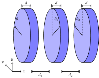
In this paper we use the Pancharatnam method pancharatnam_achromatic_1955 ; pancharatnam_achromatic_1955-1 to increase the usable bandwidth. Originally developed for wave plates operating at optical frequencies, the same method can be applied at any frequency e.g. at millimetre wavelengths murray_imaging_1997 , as well as with different polarisation manipulation technologies e.g. waveguide based polarisation rotators pisano_broadband_2011 . The Pancharatnam method requires a number of wave plates to be placed one after the other with their optic axes rotated by specific angles. This is similar to the schematic shown in Fig. 1, although when using wave plates made from regular birefringent materials, they are typically in physical contact with one another. A single wave plate of thickness, , and birefringence, , is only able to produce the required at a single frequency. By using wave plates rotated by different angles, , the required may be crossed at different frequencies. By optimising the rotation angles of the cascaded set of wave plates, a broadening of the usable bandwidth can be achieved.
III Design, Modelling and Optimisation
Metallic meshes are generally made as a two-dimensional array of repeated structures. These can be simulated using commercial electromagnetic Finite Element Method (FEM) solvers such as Ansys HFSS ansys_hfss_2010 by modelling just the smallest repeatable element, the unit cell. By applying periodic boundary conditions to the unit cell, an infinite two-dimensional array of cells can be easily simulated without requiring large computing resources.
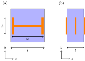
The unit cell design adopted in this work is based on a “dog bone” structure (Fig. 2), previously used in zhou_experimental_2006 . The design was chosen for its birefringent properties, and its ability to produce a NRI band only along a single polarisation direction. The final structure consisted of three copper dog bone grids supported by a polypropylene (, lamb_miscellaneous_1996 ) substrate. Henceforth this structure will be referred to as a dog bone triplet (DBT). The dimensions of the dog bones and the thickness of the substrate were optimised so that a single unit cell would be able to produce at , the centre of the W-band (). Additionally the transmitted intensity along the - and -polarisations, was at the same frequency. The final optimised dimensions are listed in the caption of Fig. 2.
Due to the Pancahratnam method requiring a number of wave plates to be cascaded one after the other with different arbitrary angles, the available periodic boundary conditions in HFSS could not be used on a cascaded set of DBT unit cells. The use of FEM modelling to optimise the Pancharatnam based HWP would have required a set of cascaded full sized DBT based HWPs. This would have been computationally prohibitive in terms of the CPU time and RAM required.
Our alternative approach is based on a transmission line (TL) model. The use of TL modelling for meshes is well known marcuvitz_waveguide_1965 ; ulrich_far-infrared_1967 and involves the individual grids being represented by a suitable combination of lumped elements e.g. capacitors and inductors. Different grid designs can be represented by equivalent circuits based on different combinations of lumped elements. Using available analytical equations, the frequency dependent behaviour of the grid may be easily computed. When modelling a cascade of grids, each grid can be represented by a transmission matrix, such as those described in pozar_microwave_2012 . The matrix elements are still based on the same analytical equations. To calculate the final transmission and reflection of such devices, the much less computationally intensive process of matrix multiplication can be carried out.
However, this method of analytical matrix seeding is unsuitable when very accurate values of the phase are required pisano_broadband_2012 . To achieve accurate phase values, data obtained from FEM simulations of the grids were used to “seed” the matrix elements, instead of relying on quantities derived analytically. To do this, the S-parameters from an FEM simulation are extracted and converted into ABCD transmission matrices pozar_microwave_2012 . The exact formalism of the Pancharatnam method used is based on adachi_analysis_1960 ; savini_achromatic_2006 , where rotation matrices are used to allow the modelling of the wave plates’ rotations. A TL model consisting of three DBT HWPs was optimised by varying the rotation angles of the individual HWPs and the thickness of the air gaps between them. The optimisation goal was set to maximise the frequency range where and the transmitted intensities for both polarisations were equal to each other. Using the nomenclature from Fig. 1 the optimised parameters were: , and .
IV Manufacture
The manufacture of the individual dog bone grids was carried out using standard photolithographic techniques. The process involves evaporating a layer of copper on to a polypropylene substrate. The copper is then coated with an even layer of positive photoresist. A photomask consisting of the positive of the grid design is placed over the sample and the entire system is exposed to ultraviolet (UV) radiation. The sample is then etched to remove the regions of copper where the photoresist was exposed to the UV radiation, leaving behind the copper that was protected by the photomask.
To create the individual DBT HWPs, three grids were manually aligned on top of each another with polypropylene spacers placed between them to provide the necessary separations. The individual grids and layers of polypropylene were then hot pressed together inside a vacuum oven to form a single structure. To provide support to the HWPs as well as provide the required thickness of the air gaps between them, the HWPs were mounted on thick aluminium rings. Transmission measurements of the individual HWPs were then taken to test their performance before they were combined into the full Pancharatnam HWP structure.
The Pancharatnam HWP was then created by stacking the individual ring mounted HWPs on top of each other. To ensure the HWPs were rotated by the correct amount the required rotation angles were marked on to the circumference of the rings and the markings were used to aid the aligning.
V Experimental Setup
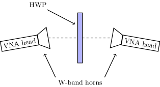
Normal incidence transmission measurements were taken using the experimental setup shown in Fig. 3. The Pancharatnam HWP is held in a specially designed holder between the two W-band heads of a Rhode & Schwarz ZVA40 Vector Network Analyser (VNA). The heads are placed off-axis to one another but at the same height and in such a way that the line connecting the two heads bisect the HWP perpendicularly. Having the heads off-axis allows the reduction of unwanted standing waves between the HWP and the heads. Although the HWP is no longer illuminated using the central portion of the horn beams, the polarisation vectors of the emitting and receiving heads are still aligned. This is crucial for polarisation measurements where cross polarisation leakages needs to be minimised. The requirement that the line connecting the horns perpendicularly bisect the HWP means that it is illuminated by a nearly planar wave front, closely matching the conditions that were modelled. Eccosorb was appropriately placed around the setup to further reduce unwanted reflections.
Due to the existence of a NRI along the -axis, -polarised radiation incident at non-normal angles would be refracted in the opposite manner within the wave plate than if it had a PRI. For a single DBT this behaviour could be detected by measuring the lateral shift of the transmitted beam alici_direct_2009 . However in our experimental setup, although the VNA heads were positioned off-axis, the radiation incident on the plate was at almost normal incidence and the effect was neither expected nor observed. In the case of the full Pancharatnam HWP illuminated with off-axis radiation, the behaviour would be even more complicated, both due to the DBTs optic axes being rotated with respect to one another as well as the polarisation dependent behaviour observed with non-normal incidence on metal mesh grids pisano_polarisation_2006 .
VI Data Analysis
VI.1 Single HWP Performance
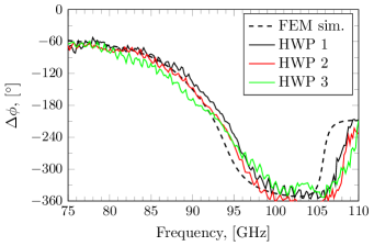
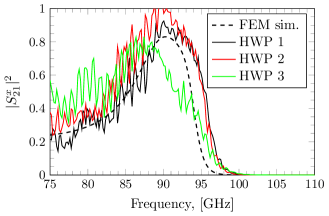
A FEM simulated frequency sweep of the optimised DBT grid showed that a single HWP made from a single DBT grid was able to meet the set requirements. between and , providing a usable fractional bandwidth of (Fig. 4, dashed line). This narrow bandwidth is caused by the large magnitude of ’s gradient when it crosses . The steepness is a result of the resonance required to produce a NRI region. VNA readings were taken of the individual HWPs to test their performance before combining them to form the Pancharatnam HWP and the results are shown in Fig. 4 as solid lines. All three manufactured HWPs show agreement with the FEM simulation data of Fig. 4 (dashed line). HWPs 1 and 2 show the best agreement, only drifting from the FEM data above where the measured data becomes blue-shifted by . HWP 3 differs slightly more than the first two HWPs with its measured showing a shallower gradient causing its to be lower than the expected value between and greater than the expected value above .
The simulated transmitted intensities along the - and -polarisations, and , are shown as dashed lines in Fig. 5 and Fig. 6. Within the defined usable bandwidth, the mean are for -polarised radiation and for -polarised radiation. Whilst shows a resonance, peaking at , remains unaffected by the DBT, instead showing a slow decrease in intensity, but remaining above across the entire W-band. The measured and of the individual HWPs are shown in Fig. 5 and Fig. 6 as solid lines. Like the data we see that HWPs 1 and 2 show good agreement with the expected data. However HWP 3 shows deviations for both - and -polarisations.
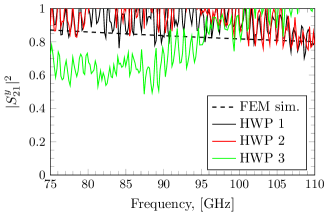
The cause for the observed deviations in , and from the expected behaviour is misalignment between the grids that make up the individual HWPs. These misalignments can be translational and rotational, with only the former being easily simulated with the single unit cell and periodic boundary condition setup in HFSS.
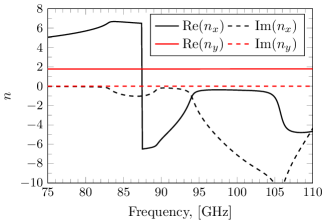
The simulated refractive indices, and , are shown in Fig. 7. In the -axis, the HWP is able to produce a NRI band above whilst the refractive index along the -axis remains constant. The values were obtained using the and data and applying a parameter extraction method chen_robust_2004 . The thickness used in the parameter extraction calculation was the physical thickness of the DBT grid, , the sum of the substrate thickness, , and the thicknesses of the copper on the outer surfaces (Fig. 2).
VI.2 Pancharatnam HWP Performance
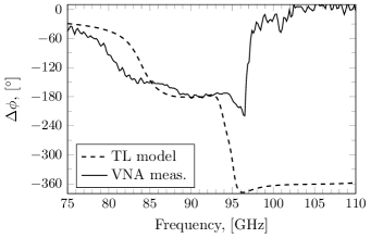
Using the TL based model with the optimised parameters, the expected is shown as the dashed line in Fig. 8. Comparing this to the behaviour of the single HWPs it can be seen that there is a flattening of between . This means the usable fractional bandwidth has been increased by almost 18 times to . This demonstrates that even if the individual HWPs have very high gradients of , the Pancharatnam method can still produce a flat region in . Broader bandwidths can be attained by using more HWPs.
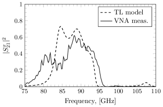
The measured readings of , shown as the solid line in Fig. 8, shows some agreement with the expected data from the TL model between . The important result to note is a plateau of is observed albeit only between , a fractional bandwidth of . Above , appears to deviate greatly from the TL model, but it should noted that in this region goes to zero (Fig. 9), meaning accurate measurements of arg() becomes difficult to obtain.
The TL modelled values of and are shown as dashed lines in Fig. 9 and Fig. 10 respectively. The expected for the - and -polarisations is reduced compared to the performance of a single HWP. In the usable band, the mean values of and were and respectively, with the peak values reaching and respectively around . The transmitted intensities of the two polarisations also show minimal dichroism within this band with the two values showing close overlap.
The measured readings of and are shown as solid lines in Fig. 9 and Fig. 10 respectively. The measured data shows some agreement with the expected TL modelled data, being lower in intensity and flatter in profile, with the peak intensities in the usable band for both polarisations being around .

The discrepancies shown in the measured , and are due to the deviations from the expected behaviour of the individual HWPs, especially that of HWP 3. Remarkably however, despite these deviations, flattening of is still observed, demonstrating that the HWPs made via the Pancharatnam method show some resilience to manufacturing errors.
VII Conclusions
In this paper, a highly birefringent metamaterial was created that was capable of producing a NRI and a PRI along orthogonal polarisation axes. This was used to create a HWP with a narrow usable fractional bandwidth defined as of . Three of these HWPs were cascaded according to the Pancharatnam method to increase the usable bandwidth. TL based modelling of the Pancharatnam setup was able to increase this substantially, bringing the fractional bandwidth to . Experimentally measured data taken with the manufactured Pancharatnam HWP showed a flattening of in bandwidth between . The reduced performance was due to the misalignment of the grids that made up the individual HWPs.
This work verifies the ability of the Pancharatnam method to create a broadening of the region where is flat even when the initial gradients of the constituent wave plates is very steep. Broader bandwidths would be achievable by cascading a greater number of HWPs, but this would come at the price of lower transmitted intensities.
Acknowledgements.
The first author was funded by a studentship provided by the Science and Technology Facilities Council (STFC).References
- (1) R. Ulrich, “Far-infrared properties of metallic mesh and its complementary structure,” Infrared Physics 7, 37–55 (1967).
- (2) J. B. Pendry, “Negative refraction makes a perfect lens,” Physical Review Letters 85, 3966 (2000).
- (3) P. Weis, O. Paul, C. Imhof, R. Beigang, and M. Rahm, “Strongly birefringent metamaterials as negative index terahertz wave plates,” Applied Physics Letters 95, 171104–3 (2009).
- (4) S. Pancharatnam, “Achromatic combinations of birefringent plates. Part I. An achromatic circular polarizer,” Proceedings of the Indian Academy of Sciences, Section A 41, 130–136 (1955).
- (5) S. Pancharatnam, “Achromatic combinations of birefringent plates. Part II. An achromatic quarter-wave plate,” Proceedings of the Indian Academy of Sciences, Section A 41, 137–144 (1955).
- (6) M. N. Afsar, “Precision Millimeter-Wave Dielectric Measurements of Birefringent Crystalline Sapphire and Ceramic Alumina,” IEEE Transactions on Instrumentation and Measurement IM-36, 554–559 (1987).
- (7) J. W. Lamb, “Miscellaneous data on materials for millimetre and submillimetre optics,” International Journal of Infrared and Millimeter Waves 17, 1997–2034 (1996).
- (8) A. G. Murray, R. Nartallo, C. V. Haynes, F. Gannaway, and P. A. R. Ade, “An imaging polarimeter for SCUBA,” in “The Far Infrared and Submillimetre Universe”, 401, 405–408 (1997).
- (9) G. Pisano, S. Melhuish, G. Savini, L. Piccirillo, and B. Maffei, “A Broadband W-Band Polarization Rotator With Very Low Cross Polarization,” IEEE Microwave and Wireless Components Letters 21, 127–129 (2011).
- (10) http://www.ansys.com/Products/Simulation+Technology/Electromagnetics/Signal+Integrity/ANSYS+HFSS.
- (11) J. Zhou, T. Koschny, L. Zhang, G. Tuttle, and C. M. Soukoulis, “Experimental demonstration of negative index of refraction,” Applied Physics Letters 88, 221103–3 (2006).
- (12) N. Marcuvitz, ed., Waveguide Handbook, vol. 10 of Massachusetts Institute of Technology Radiation Laboratory (Dover Publications Inc., New York, 1965).
- (13) D. M. Pozar, Microwave engineering (Wiley, Hoboken, NJ, 2012), 4th ed.
- (14) G. Pisano, M. W. Ng, V. Haynes, and B. Maffei, “A broadband metal-mesh half-wave plate for millimetre wave linear polarisation rotation,” Progress In Electromagnetics Research M 25, 101–114 (2012).
- (15) S. Adachi and E. M. Kennaugh, “The analysis of a broad-band circular polarizer including interface reflections,” IRE Transactions on Microwave Theory and Techniques 8, 520–525 (1960).
- (16) G. Savini, G. Pisano, and P. A. R. Ade, “Achromatic half-wave plate for submillimeter instruments in cosmic microwave background astronomy: modeling and simulation,” Applied Optics 45, 8907–8915 (2006).
- (17) K. B. Alici and E. Ozbay, “Direct observation of negative refraction at the millimeter-wave regime by using a flat composite metamaterial,” Journal of the Optical Society of America B 29, 1688–1692 (2009).
- (18) G. Pisano, P. A. R. Ade, and S. Weaver, “Polarisation effects investigations in quasi-optical metal grid filters,” Infrared Physics and Technology 48, 89–100 (2006).
- (19) X. Chen, T. M. Grzegorczyk, B.-I. Wu, J. Pacheco, and J. A. Kong, “Robust method to retrieve the constitutive effective parameters of metamaterials,” Physical Review E 70, 016608 (2004).