Narrowing the filter cavity bandwidth via optomechanical interaction
Abstract
We propose using optomechanical interaction to narrow the bandwidth of filter cavities for achieving frequency-dependent squeezing in advanced gravitational-wave detectors, inspired by the idea of optomechanically induced transparency. This can allow us to achieve a cavity bandwidth on the order of one hundred Hz using small-scale cavities. Additionally, in contrast to a passive Fabry-Pérot cavity, the resulting cavity bandwidth can be dynamically tuned, which is useful for adaptively optimizing the detector sensitivity when switching amongst different operational modes. The experimental challenge for its implementation is a stringent requirement for very low thermal noise of the mechanical oscillator, which would need superb mechanical quality factor and very low temperature. We consider one possible setup to relieve this requirement by using optical dilution to enhance the mechanical quality factor.
Introduction.—Advanced interferometric gravitational wave (GW) detectors, e.g., the advanced LIGO Abbott2009 , advanced VIRGO aVir2009 and KAGRA Somiya2012 , are expected to be limited by quantum noise over almost the entire detection band. Further enhancement of the detector sensitivity requires manipulation of the optical field and the readout scheme at the quantum level. One approach proposed by Kimble et al. Kimble2001 is injecting frequency-dependent squeezed light into the main interferometer. A series of optical cavities is used to filter the squeezed light and to create proper rotation of the squeezing angle at different frequencies. In order to achieve a broadband reduction of quantum noise, the frequency scale of these filter cavities needs to match that of quantum noise of the main interferometer. For the advanced LIGO, the quantum noise is dominated by quantum radiation pressure noise at low frequencies and shot noise at high frequencies—the transition happens around 100Hz, which determines the required filter cavity bandwidth.
The original proposal in Ref. Kimble2001 is using filter cavities of kilometer length. Recently, Evans et.al Evans2013 proposed a more compact (10 meters) filter cavity with finesse to achieve the required bandwidth. With such a high finesse, a small optical losses can degrade the squeezing and become the key limiting factor in the filter cavity performance. Isogai et.al have experimentally demonstrated that the optical losses from current mirror technology are sufficiently small to build such a filter cavity that will be useful for the advanced LIGO Isogai2013 . However if we want to further increase the compactness of the filter cavity, then the requirement for optical loss becomes more stringent. In this case, one solution is to go beyond the paradigm of passive cavities. One proposed approach is to actively narrow the cavity bandwidth by using electromagnetically induced transparency (EIT) effect in a pumped atomic system Mikhailov2006 . In principle, the cavity can be made to be on the centimeter-scale while still having a bandwidth comparable to a much longer high-finesse cavity. Additionally, with an active element, the cavity optical properties can be dynamically tuned by changing the power of the control pumping field. This has the advantage of allowing optimization of the filter cavity for different operational modes of the detector, where the quantum noise has different frequency dependencies, e.g., tuned vs. detuned resonant sideband extraction (RSE) in the case of the advanced LIGO.
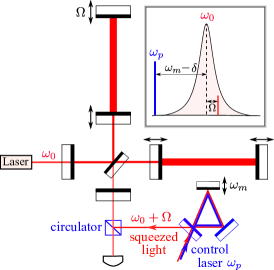
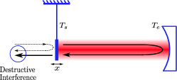
The active atomic system is generally lossy, which will degrade the squeezing level. Here we propose to narrow the filter cavity bandwidth using the optomechanical analogue of EIT, optomechanically induced transparency (OMIT), which has recently been experimentally demonstrated by Weis et al. Weis2010 and Teufel et al. Teufel2011 . In comparison with these OMIT experiments, we consider a different parameter regime and use an overcoupled cavity to attain the desired performance. The scheme integrated with the main interferometer is illustrated in Fig. 1. The filter cavity consists of a mirror-endowed mechanical oscillator with eigenfrequency that is much larger than the cavity bandwidth . A control pump laser drives the filter cavity at frequency , detuned from the cavity resonant frequency (also the laser frequency of the main interferometer) by with comparable to the gravitational-wave signal frequency . As we will show, the optomechanical interaction modifies the cavity response and gives rise to the following input-output relation for the sideband at :
| (1) |
where is defined as:
| (2) |
with being the intra-cavity power of the control field, the mass of the mechanical oscillator and the transmissivity of the front mirror (the end mirror is totally reflective). The first term in Eq.1 gives the input-output relation of a standard optical cavity with the original cavity bandwidth replaced by , which can be significantly smaller than as well as dynamically tuned by changing the control beam power.
The second term arises from the thermal fluctuation of the mechanical oscillator. It is uncorrelated with the input optical field and therefore decohering the squeezed light. In order for its effect to be small, we require:
| (3) |
with the mechanical quality factor and the environmental temperature. Given the fact that the desired effective cavity bandwidth is Hz, we have
| (4) |
This is challenging to achieve even with low-loss materials at cryogenic temperature. A possible solution is to use optical dilution, first proposed by Corbitt et al. Corbitt2007 ; Corbitt2007b ; Chang2012 ; Ni2012 . It allows for a significant boost of the mechanical quality factor by using the optical field, to provide most of the restoring force. Later we illustrate its applicability for our purpose.
Optomechanical dynamics.—Here we provide the details behind Eq. (1) by analyzing the dynamics of the optomechanical filter cavity, starting from the standard linearized Hamiltonian Wilson-Rae2007 ; Marquardt2007 :
| (5) |
In the Hamiltonian, is the annihilation operator of the cavity mode and is the annihilation operator for the input optical field (the squeezed light in our case); is the oscillator position (momentum); with being the cavity length. In the rotating frame at frequency of the control laser, the Heisenberg equation of motion reads:
| (6) | ||||
| (7) |
where is the detuning frequency and we have included the mechanical damping and associated Langevin force . Solving these equations of motion in the frequency domain yields
| (8) | ||||
| (9) |
We have defined the susceptibilities and .
Relevant parameter regime.—We consider the parameter regime leading to Eq. (1). This requires with , and the so-called resolved-sideband regime . Correspondingly, the lower sideband of the cavity mode in Eq. (8) is negligibly small and can be ignored (we will analyze the effect of this approximation later). We therefore obtain [cf. Eqs. (8) and (9)]:
| (10) |
Since we are interested in the signal sidebands around , we rewrite the above expression in terms of by using the equality [cf. the inset of Fig. 1]. Given , we have and Together with , we obtain
| (11) |
with the additional noise term defined as
| (12) |
For a high quality factor oscillator , we can ignore and recover the input-output relation shown in Eq. (1).
To maintain coherence of the squeezed light, the fluctuations due to the thermal noise term need to be much smaller than those due to the input field; equivalently, the quantum radiation pressure noise on the mechanical oscillator from the squeezed light needs to dominate over thermal noise of the oscillator. Given the fact that , the requirement on the noise spectrum for reads
| (13) |
The thermal noise effect is maximal around , from which we obtain the condition shown in Eq. (3).
Effects of optical loss and finite cavity bandwidth.—Apart from the above-mentioned thermal noise, there are other decoherence effects: (i) the additional radiation pressure noise introduced by the optical loss, and also (ii) the effect of the lower sideband due to the finite cavity bandwidth, ignored in the resolved-sideband limit. Their effects are similar to the above thermal force noise; therefore we can quantify their magnitude using the noise spectrum referred to the output. For the optical loss,
| (14) |
where is the magnitude of the optical loss (e.g., for 10ppm loss). Similarly, for the contribution from the lower sideband, we have
| (15) |
These two need to be taken into account when estimating the performance of this optomechanical filter cavity.
Possible experimental scheme.—We have shown in Eq. (4) that the most significant issue is the thermal noise, which puts a stringent requirement on the mechanical system and the environmental temperature. As we mentioned earlier, One possible way to mitigate this is using optical dilution explored by Corbitt et al., in which the optical restoring force is due to the linear dependence of radiation pressure force on the oscillator position. This scheme has a limitation from quantum back action noise associated with a linear position response. Korth et al. Korth2012 , have showed how measurement-based feedback can cancel the quantum back action. Such a cancellation is, however, limited by quantum efficiency of the photodiode for measurement.
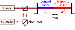
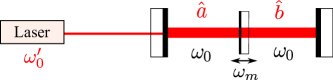
Here we consider optical dilution using a coupled cavity scheme, shown in Fig.2, with a mirror-endowed oscillator placed in the middle of a Fabry-Pérot cavity, first implemented by Thompson et al. Thompson2008 ; Jayich2008 . Interestingly, this scheme allows for an internal cancellation of the quantum back action associated with a linear optical spring, and thus it avoids the limitation of the scheme in Ref. Korth2012 . A detailed analysis is given in the supplemental material Supplemental . An intuitive picture behind this back-action evasion effect can be described as follows. The optical field on the left-hand side of the middle oscillator consists of two parts: (i) the immediate reflection from the oscillator and (ii) the transmitted field from the right-hand side, both containing the position information of the oscillator. The coupled cavity has a doublet resonance. It turns out that, when the trapping field is resonantly tuned to one of the doublet and the end mirror is perfectly reflective, the position information from these two parts destructively interfere, resulting in a cancelation of the back action.
Strong trapping beam can induce an optical spring frequency with:
| (16) |
where and are the input power and optical frequency of the trapping beam, the and are the transmissivity of the mirror-endowed oscillator and the front mirror, respectively. The modified quality factor can be greatly boosted since the mechanical dissipation rate is unchanged.
This optical dilution scheme also has its own limitations. Firstly, in reality there is no perfectly reflective mirror and always some optical loss, and so the above-mentioned cancellation cannot be perfect. The residual radiation pressure noise, referred to the output, is given by:
| (17) |
Secondly, the optical spring effect is frequency dependent: . This tells us that the optical spring can modify not only the resonance frequency, but also the mechanical damping and the effective inertia (mass), which could induce instability. Lastly, finite absorption of the laser power in the oscillator will increase its temperature and may increase the thermal noise. The size of this effect, however, depends on the mechanical structure and the detailed loss mechanism.
An example.—We illustrate the requirements for experimentally realizing the optomechanical filter cavity using optical dilution shown in Fig. 2 with some example parameters in Table 1. These values are chosen after considering the above mentioned effects, which can cause decoherence to the squeezed light, such that
| (18) |
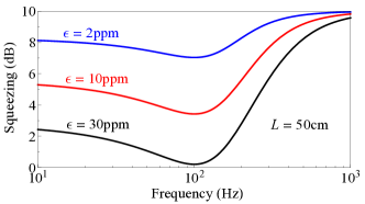
In addition, once we fix the oscillator mass and transmissivity , we can minimize by looking into the scaling of different parameters, which determines the trapping beam power , the front mirror transmissivity , and the environmental temperature . We end up with the following scaling of in terms of optical loss and cavity length:
| (19) |
The resulting degradation to the squeezing factor due to optical loss is shown in Fig. 3 for a cavity length of 50cm. In comparison to a passive filter cavity for which the performance degrades as Isogai2013 , the optomechanical filter cavity using the optical-dilution scheme has a milder dependence on , which yields the possibility of being small scale.
| Parameter | Description | Value |
|---|---|---|
| filter cavity length | 50cm | |
| front mirror transmissivity | 250ppm | |
| transmissivity of oscillator | 3000ppm111This value is only for the trapping beam; for the control field, the value is close to unity (limited by optical loss), requiring a dichroic coating. | |
| trapping beam input power | 1.6mW | |
| trapping beam wavelength | 532nm | |
| oscillator mass | 500ng | |
| bare mechanical frequency | 200Hz | |
| bare mechanical quality factor | 222According to Cagnoli2000 , the mechanical damping of some material structures are as small as Hz, which sets this possible value. | |
| environmental temperature | 1K | |
| control beam intra-cavity power | 0.1mW | |
| control beam wavelength | 1064nm | |
| effective cavity bandwidth | 100Hz |
| optical spring frequency [Eq.(16)] | 20kHz | |
|---|---|---|
| final mechanical quality factor | ||
| optical (anti-)damping rate [Eq.(A.9)] | mHz | |
| negative optical inertia [Eq.(A.10)] | pg |
The mechanical dynamics are modified by the opto-mechanical interaction, and the new effective parameters of the oscillator are summarised in Table 2. The optical spring shifts the mechanical resonant frequency from its bare value of 100Hz to 20kHz, which results in a two hundred fold increase in the quality factor. Comparing Table 1 and Table 2, we can see that the negative optical damping and inertia do not pose an important problem.
We would like to point out that this scheme might not function as expected due to heating from finite absorption of the laser power. The intra-cavity power of the trapping beam, given the listed parameter values, is around 10W. For 10 ppm absorption, this amounts to mW of heat deposited into the nano-mechanical oscillator. We make an order-of-magnitude estimate in the supplemental material and find this can create a nonuniform temperature distribution with a maximum around 10K near the beam spot. Further detailed study is required to estimate how this nonuniform temperature distribution on the oscillator affects the total thermal noise. Specifically in this case, the dissipation mainly comes from the clamping point where the temperature is still low. If this nonuniform temperature distribution indeed introduces significant thermal noise, then alternative materials with higher thermal conductivity at low temperature would need to be manufactured.
Conclusion.—We have considered the use of optomechanical interaction to narrow the bandwidth of a filter cavity for frequency-dependent squeezing in future advanced gravitational-wave detectors. However, due to susceptibility to thermal decoherence, its feasibility is conditional on advancements in low-loss mechanics and optics.
Acknowledgements.—We thank Huan Yang, David McCelland, Farid Khalili, Li Ju and Jiayi Qin for fruitful discussions. Y.M., S.D., C.Z., R.W., and D.B. have been supported by the Western Australia Centers of Excellence program, and by the Australian Research Council; W.Z.K. is supported by NSF Grant PHY-0757058; H.M. and Y.C. are supported by NSF Grants PHY-1068881 and CAREER Grant PHY-0956189.
References
- (1) B. P. Abbott et al., Reports on Progress in Physics 72, 076901 (2009).
- (2) Advacnced VIRGO project: https://wwwcascina.virgo.infn.it/advirgo/.
- (3) K. Somiya, Class. Quantum Grav. 29, 124007 (2012).
- (4) H. J. Kimble, Y. Levin, A. B. Matsko, K. S. Thorne, and S. P. Vyatchanin, Phys. Rev. D 65, 022002 (2001).
- (5) M. Evans, L. Barsotti, P. Kwee, J. Harms, and H. Miao, Phys. Rev. D 88, 022002 (2013).
- (6) T. Isogai, J. Miller, P. Kwee, L. Barsotti, and M. Evans, Optics Express, 21, 30114 (2013).
- (7) E. E. Mikhailov, K. Goda, T. Corbitt, and N. Mavalvala, Phys. Rev. A 73, 053810 (2006).
- (8) S. Weis, R. Riviére, S. Delèglise, E. Gavartin, O. Arcizet, A. Schliesser, and T. J. Kippenberg, Science 330, 1520 (2010).
- (9) J. D. Teufel, D. Li, M. S. Allman, K. Cicak, A. J. Sirois, J. D. Whittaker, and R. W. Simmonds, Nature 471, 204 (2011).
- (10) T. Corbitt, Y. Chen, E. Innerhofer, H. Muller-Ebhardt, D. Ottaway, H. Rehbein, D. Sigg, S. Whitcomb, C. Wipf, and N. Mavalvala, Phys. Rev. Lett. 98, 150802 (2007).
- (11) T. Corbitt, C. Wipf, T. Bodiya, D. Ottaway, D. Sigg, N. Smith, S. Whitcomb, and N. Mavalvala, Phys. Rev. Lett 99, 160801 (2007).
- (12) D. E. Chang, K.-K. Ni, O. Painter, and H. J. Kimble, New J. Phys. 14, 045002 (2012).
- (13) K.-K. Ni, R. Norte, D. J. Wilson, J. D. Hood, D. E.Chang, O. Painter, and H. J. Kimble, Phys. Rev. Lett. 108, 214302 (2012).
- (14) I. Wilson-Rae, N. Nooshi, W. Zwerger and T. J. Kippenberg, Phys. Rev. Lett. 99, 093901 (2007).
- (15) F. Marquardt, J. P. Chen, A. A. Clerk, and S. M. Girvin, Phys. Rev. Lett. 99, 093902 (2007).
- (16) W. Z. Korth, H. Miao, T. Corbitt, G. D. Cole, Y. Chen, and R. X. Adhikari, Phys. Rev. A 88, 033805 (2013).
- (17) J. D. Thompson, B. M. Zwickl, A. M. Jayich, F. Marquardt, S. M. Girvin, and J. G. E. Harris, Nature 452 72, (2008).
- (18) A. M. Jayich, J. C. Sankey, B. M. Zwickl, C. Yang, J. D. Thompson, S. M. Girvin, A. A. Clerk, F. Marquardt, and J. G. E. Harris, New J. Phys. 10, 095008 (2008).
- (19) See Supplemental Material. which includes Refs. Miao2009 ; Meirovitch1967 ; Glassbrenner1964 .
- (20) G. Cagnoli, L. Gammaitoni, J. Hough, J. Kovalik, S. McIntosh, M. Punturo and S. Rowan. Phys. Rev. Lett. 85, 2442 (2000).
- (21) H. Miao, S. Danilishin, T. Corbitt, and Y. Chen, Phys. Rev. Lett. 103, 100402 (2009).
- (22) L. Meirovitch Analytical Methods in Vibrations. Prentice Hall (1967).
- (23) C. J. Glassbrenner and G. A. Slack, Phy. Rev. 134, A1058 (1964).
In this supplemental material, we will show additional details and derivations for the optomechanical dynamics of the optical-dilution scheme shown in Fig. 2 of the main text.
.1 Hamiltonian and equation of motion
The Hamiltonian of the system can be written as:
| (A.1) |
Here, are annihilation operators for cavity modes in left and right sub-cavity (with resonant frequency ) respectively. are the position and momentum operators of the vibrating mirror. is the coupling constant for and and is defined to be . and correspond to the coupling of the system to the environment.
The Heisenberg equations of motion in the rotating frame of the trapping beam at frequency can be derived as:
| (A.2a) | |||
| (A.2b) | |||
| (A.2c) | |||
| (A.2d) | |||
Here, and , and are the transmissivity of the front mirror and the loss of the system through the end mirror, is the detuning of the pumping laser field with respect to the half-cavity resonance. Suppose we pump the cavity by injecting a laser field through the front mirror (single-side pumping), then . These equations can be solved perturbatively. The zeroth order terms give us the classical amplitude of the intra-cavity mode in both sub-cavities and the first order terms carry information about the mirror vibration along with quantum noise due to the non-zero transmissivity of the cavity end mirror.
From the above Heisenberg equations of motion, we have the steady state fields in the two sub-cavities:
| (A.3a) | |||
| (A.3b) | |||
As we can see from above equations, when we set the detuning of the trapping beam to be and set , the intracavity field amplitude is strong: with . The fluctuating field consists of mechanical modulation and quantum fluctuations as:
| (A.4a) | |||
| (A.4b) | |||
with and (notice that in case of , we have ). The radiation pressure force acting on the trapped mirror is given by
| (A.5) |
which can be split into two parts:
| (A.6) |
The first and second term represent the pondermotive modification of the mechanical dynamics and the back-action quantum radiation pressure noise respectively. The here is the optomechanical rigidity which can be expanded in terms of if the typical frequency of mechanical motion is smaller than the other frequency scale in the trapping system:
| (A.7) |
The first term in (A.7) gives the trapping frequency and the second and third terms give the velocity and acceleration response of the trapped mirror which are optical (anti-)damping and optomechanical inertia , respectively.
Substituting (A.3) and (A.4) into (A.5) and taking the expansion with respect to detection frequency , we can get analytical expressions of the optical rigidity and radiation pressure noise. However, they are too cumbersome to show. In the following, we show approximate results in the interesting parameter region of and in which the back-action noise can be coherently canceled.
.2 Dynamics and back-action
The optical spring frequency is given by:
| (A.8) |
Substitute , , and in, and we have Eq.(16) in the main text. The here describes all the high order terms with . Notice that this optical spring can be treated effectively as a quadratic trap of the vibrating mirror on the anti-node of our trapping beam as shown in 333H. Miao, S. Danilishin, T. Corbitt, and Y. Chen, Phys. Rev. Lett. 103, 100402 (2009)
The optical (anti)-damping factor is given by (to order of ):
| (A.9) |
It is clear from this formula that in the ideal case when and , the optical damping is completely cancelled. Therefore by carefully choosing the system parameters, we can achieve a small positive damping when the end mirror is not perfectly reflective.
The main contribution to the optomechanical inertia is at zeroth order of :
| (A.10) |
which is extremely small as we have shown in the main text.
Finally, the back-action radiation pressure force noise spectrum is given by:
| (A.11) |
Notice that the back-action force spectrum is zero when the end mirror is perfectly reflective ().
The physical explanation of this back-action evasion phenomenon is shown in Fig.A.5. The part of the outgoing fields which contains the displacement signal can be written as (suppose the end mirror is perfectly reflective):
| (A.12) |
The first term on the right hand-side is the field directly reflected from the trapped mirror while the second term is the field transmitted out of the cavity. We can see that they cancel when . Therefore in this case the output field does not contain the -information.
Given the parameters listed in Tab.I of the main text, we use (A.8)-(A.11) to calculate the modification of the mechanical dynamics by the trapping beam, and list the effective parameters in Tab.II of the main text. We can see that velocity response is a mechanical damping factor which will not cause instability and is too small to affect the OMIT effective cavity bandwidth . The negative inertia is also too small to be comparable to the mass of the mechanical oscillator.
I Effective temperature of the mirror-endowed oscillator
Here we estimate the temperature of the mirror-endowed oscillator due to the additional heating caused by optical absorption. We assume the oscillator to be a silicon cantilever mirror with thickness , Young’s modulus and density . Under the assumption that , the fundamental frequency of the cantilever is given by 444L. Meirovitch Analytical Methods in Vibrations. Prentice Hall (1967)
| (A.13) |
where the and are the cross-sectional area and length of the cantilever. Then is the moment of inertia of the beam cross-section. Using the parameters given in Tab. 3, the resonant frequency has the value about .
| mass density | 2329 | |
|---|---|---|
| Young’s modulus | ||
| cantilever beam length | ||
| cantilever thickness | m | |
| cantilever width | mm |
We also assume that the suspended mirror inside the cavity has thermal conductivity . The cantilever is illuminated by the trapping field with intra-cavity power . As a simple 1-D heat transport problem, Fourier’s law says that the heat power passing through the cross-section of the mirror material at distance from its center equals to . Integrating the heat transport equation from the illuminated spot center with temperature to the boundary with temperature , we have the relation between the and the absorbed power for a rectangular shape mirror as:
| (A.14) |
Typically we have at cryogenic temperature3. Using the sample parameters , and the conductivity of the material555 C. J. Glassbrenner and G. A. Slack, Phy. Rev. 134, A1058 (1964) , we have from Eq.(A.14).
How this absorption-induced 6K temperature around the hot spot and its nonuniform distribution across the beam cantilever influences the thermal noise is not entirely clear and needs further study. The loss of the cantilever motion can be classified as surface loss and body loss. The body loss is mainly through the clamping point where the temperature is around the cryogenic environment temperature. The surface loss, on the other hand, influences the cantilever motion through the coupling of the material surface motion with the local thermal bath, which has a raised temperature from the trapping beam heating. Whether the thermal noise due to surface loss degrades the squeezed light or not depends on detailed design of the experiment and needs a more sophisticated study. Moreover, the trapping beam does not illuminate the cantilever beam uniformly thereby a heat flux will be built up across the cantilever beam with temperature gradient about . The non-equilibrium thermal noise associated with this heat flux is also unclear and needs to be addressed in future research.