Measurement of the intrinsic damping constant in individual nanodisks of YIG and YIG|Pt
Abstract
We report on an experimental study on the spin-waves relaxation rate in two series of nanodisks of diameter 300, 500 and 700 nm, patterned out of two systems: a 20 nm thick yttrium iron garnet (YIG) film grown by pulsed laser deposition either bare or covered by 13 nm of Pt. Using a magnetic resonance force microscope, we measure precisely the ferromagnetic resonance linewidth of each individual YIG and YIG|Pt nanodisks. We find that the linewidth in the nanostructure is sensibly smaller than the one measured in the extended film. Analysis of the frequency dependence of the spectral linewidth indicates that the improvement is principally due to the suppression of the inhomogeneous part of the broadening due to geometrical confinement, suggesting that only the homogeneous broadening contributes to the linewidth of the nanostructure. For the bare YIG nano-disks, the broadening is associated to a damping constant . A 3 fold increase of the linewidth is observed for the series with Pt cap layer, attributed to the spin pumping effect. The measured enhancement allows to extract the spin mixing conductance found to be for our YIG(20nm)|Pt interface, thus opening large opportunities for the design of YIG based nanostructures with optimized magnetic losses.
| (G) | (nm) | (rad.s-1.G-1) | |
|---|---|---|---|
| 15 |
Yttrium iron garnet (Y3Fe5O12), commonly referred as YIG, is the champion material for magneto-optical applications as it holds the highest figure of merit in terms of low propagation loss. It is widely used in high-end microwave and optical-communication devices such as filters, tunable oscillators, or non-reciprocal devices. It is also the material of choice for magnonics serga10 , which aims at using spin-waves (SW) (or their quanta magnons) to carry and process information. The development of this emerging field is presently limited by the damping constant of SW. Recently it was proposed that spin-current transfer generated by spin Hall effect from an adjacent layer can partially or even fully compensate the intrinsic losses of the traveling SW beyond the natural decay time. The achievement of damping compensation by pure spin current in 1.3m thick YIG covered by Pt was reported by Kajiwara et al. kajiwara10 , although attempts to reproduce the results have so far failed hahn13 ; kelly13 . Given that the spin-orbit torque is purely interfacial in such hybrid system, it is crucial to work with nanometer-thick films of epitaxial YIG. Primarly, because the interface spin-current transfer scales inversely with the YIG thickness xiao12 . Secondly, because it permits nano-patterning of the YIG and thus the engineering of the spin-wave (SW) spectra through spatial confinement jorzick02 ; loubens07 ; guo13 . To the best of our knowledge, however, there is no report yet Pirro2014 on the measurement of the dynamical properties on submicron size nanostructure patterned out of YIG ultrathin films.
Benefiting from our recent progress in the growth of very high quality YIG films by pulsed laser deposition (PLD) kelly13 , here we will demonstrate that these ultra-thin YIG films (thicknesses ranging from 20 to 4 nm) can be reliably nano-patterned into sub-micron size nano-disks. In the following, we will perform a comparative study of the linewidth on these nanostructures. We will analyze the different contributions to the damping by separating the homogeneous from the inhomogeneous broadening and quantify the spin-pumping contribution when an adjacent metallic layer is added. We will also evaluate the consequences of the damages produced by the lithographic process on the dynamical response of these devices. It will be shown that the different alterations produced by chemical solvent, heat treatment, amorphization and redeposition of foreign elements during the lithography, edge roughness etc… do not produce any increase to the linewidth, offering great hope for incorporation of these YIG films in magnonics.
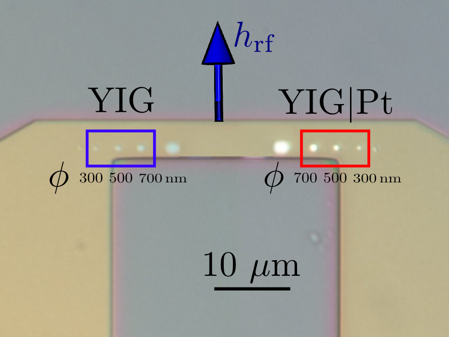
The 20 nm thick YIG has been grown by PLD on a (111) Gd3Ga5O12 substrate following the preparation described in Ref. kelly13 . A 13 nm thick Pt layer was then deposited by sputtering on half of the YIG surface. One slab of mm was cut to perform standard magnetic hysteresis and ferromagnetic resonance (FMR) measurements. The measured magnetic parameters of the bare YIG film are summarized in Table 1. On the remaining piece, a series of YIG nanodisks has been subsquently patterned using standard electron lithography and dry ion etching. After the YIG lithography, an insulating layer of 50 nm SiO2 was deposited on the whole surface and a 150 nm thick and 5 m wide microwave Au-antenna was deposited on top. Fig. 1 shows an optical image of the sample and the antenna pattern. The series of decreasing diameters bare YIG nanodisks is placed on the left. The spacing between the disks is 3 m. The series of disks on the right side mirrors the first one and has a 13 nm Pt layer on top. Here we concentrate on the disks enclosed in the rectangular area, with nominal diameter 700, 500 and 300 nm.
| (nm) | mode | (GHz) | simu. | analyt. | fit |
|---|---|---|---|---|---|
| 700 | 8.74 | 8.54 | 8.69 | 8.76 | |
| 700 | 9.14 | 9.04 | 9.10 | 9.16 | |
| 700 | 9.65 | 9.66 | 9.68 | 9.72 | |
| 500 | 9.10 | 8.73 | 8.90 | 9.05 | |
| 500 | 9.72 | 9.51 | 9.63 | 9.69 | |
| 500 | 10.52 | 10.51 | 10.72 | 10.65 | |
| 300 | 9.58 | 9.19 | 9.47 | 9.51 | |
| 300 | 10.57 | 10.66 | 11.25 | 10.63 |
To measure the FMR-spectra of the nanodisks buried under the microwave antenna, we use a ferro-magnetic resonance force microscope (f-MRFM) klein08 . It is based on measuring the deflection of a MFM-cantilever with a magnetic Fe particle of about 800 nm diameter affixed to the tip. The tip magnetic dipole moment senses the stray field produced by the perpendicular component Mz of the magnetization of the magnetic nanodisks, which is modulated by the exciting microwave power at the mechanical frequency of the cantilever.
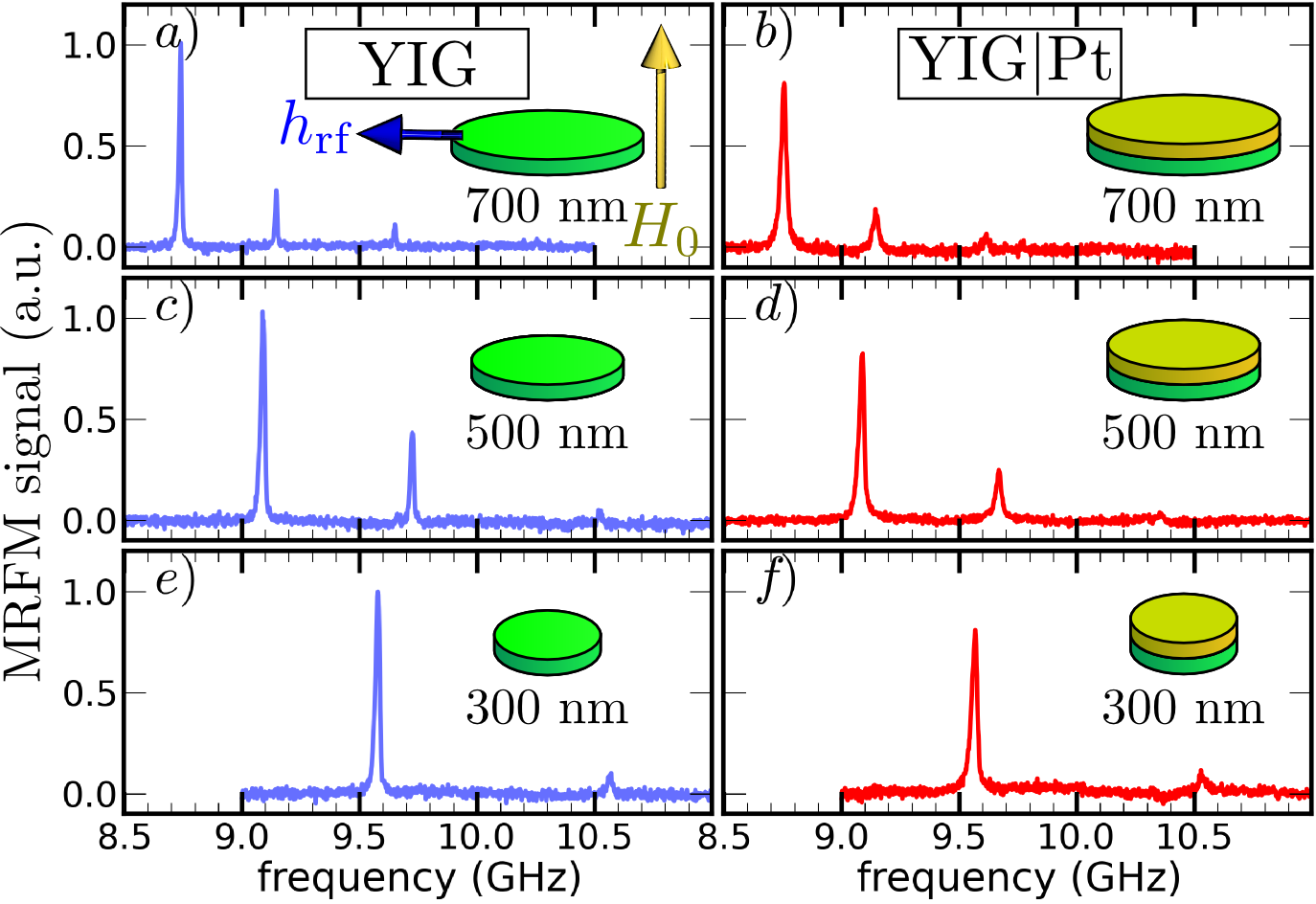
In Fig. 2 we show f-MRFM spectra recorded for different diameters (by row) on both the YIG and YIG|Pt nanodisks (by column). The spectra correspond to the spin-wave eigenmodes of the disks biased by a perpendicular magnetic field kOe. The largest peak at lowest frequency stems from the lowest energy FMR-mode, the so-called uniform mode. The smaller peaks at higher energy correspond to higher order modes. The splitting corresponds to the quantization of the SW wavenumber ( being an integer) in the radial direction klein08 . One can thus infer from the peak separation the lateral size of the disk. Using the literaturesparks64 ; Damon1965 value for the YIG exchange length nm, a fit of the peak separation leads to an effective confinement of respectively 700, 520, 380 nm for our 3 disks, assuming total pinning at the disk edge (see Table II). This is in very good agreement with nominal sizes targeted by the patterning. Differences with the nominal value are due both to imperfection of the lithographic process and the dipolar pinning condition Guslienko2002 , which scales as the aspect ratio. Confining a spin wave in a smaller volume leads also to an overall increase of the exchange and self-dipolar energy, and thus a shift of the fundamental mode with increasing energy. We have checked that the position of the peak is compatible with the magnetic parameters shown is Table I assuming that the center of the probe is approached from 3.0 to 1.5 m when moved from the largest to the smallest disk.
From the comparative measurements presented in Fig. 2, we see that the peak position is not altered by the addition of the Pt layer ontop of the YIG disk whereas its linewidth is clearly increased. To emphasize this result, Fig. 3 shows the linear f-MRFM spectra of the 700 nm bare YIG (b, blue dots) and of the YIG|Pt (c, red dots) disks. For comparison the spectrum measured on the extended YIG thin film is shown in (a, black). It was recorded with a transmission line Au-antenna of 500 m width and an in-plane external field oriented perpendicularly to the exciting microwave field, similarly to the configuration used in Ref.hahn13 .
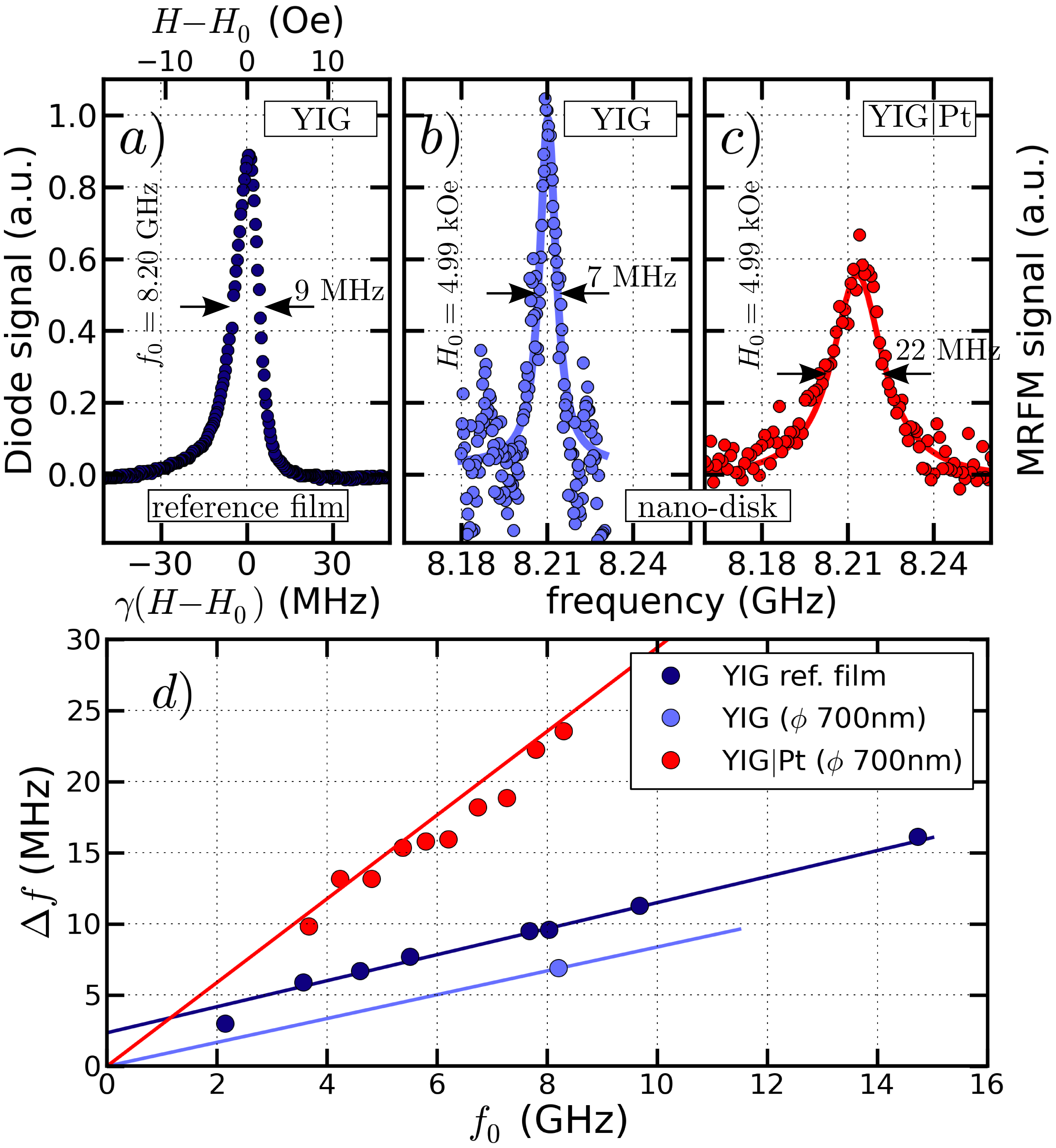
A first striking result of Fig. 3 is obtained by comparing the spectra measured in extended film (a) and the nanostructure (b) for the bare YIG: the nanopatterning improves the linewidth loubens07 . One can observe that, while the lineshape of the resonance has a Lorentzian shape in the nanostruture (continuous line), the peak shape is asymetric in the YIG film. We attribute it to inhomogeneous broadening. This is confirmed by performing experiments on different slabs of the reference film, which actually yield different lineshapes (not shown). The usual method of separating the homogeneous contribution from the inhomogeneous one is to study the frequency dependence of the half-linewidth . The slope gives , the Gilbert damping constant, while the zero frequency intercept gives the inhomogeneous contribution. In Fig. 3(d), we have thus plotted the full-linewidth of the extended reference film at different frequencies using the same color as in Fig. 3(a). The linewidth varies almost linearly with the frequency. We extract from the slope the damping 10-4, while the intercept at zero frequency indicates the amount of inhomogeneity of the resonance: =2.5 MHz (or =1 Oe).
On the same Fig. 3(d), we show using red dots the frequency dependence of the linewidth of the YIG|Pt nanostructure. The fit of the slope yields . The striking feature is that a linear fit now intercepts with the origin of coordinates. It means that the linewidth measured in the nanostructures directly yields the homogeneous contribution. For the bare YIG nanodisk it was only possible to reliably extract the linear linewidth at one point at 8.2 GHz (blue dot). Interestingly enough the slope of the straight line from this point to the origin is exactly that of the line fitted to the extended film data. We speculate by analogy to the Pt/YIG case that the linewidth in the YIG nanostructure is purely homogeneous in nature, while the intrinsic part of the damping has been unaffected by the lithographic process.
In Fig. 3, we also see that the linewidth of the 700 nm YIG|Pt disk is 22 MHz (c) i.e. about three times wider than that of the 700 nm YIG disk, which is 7 MHz (b). The influence of an adjacent Pt layer is shown to increase the damping threefold through spin-pumping effect tserkovnyak02 . The characteristic parameter for the efficiency of spin transfer across the interface and the accompanying increase of damping in YIG is the spin mixing conductance . One can directly evaluate the increase of damping induced by the presence of the Pt layer. As we find and , we deduce a large spin-pumping contribution that adds to the intrinsic damping : . From this, one can calculate the spin mixing conductance according to heinrich11 :
| (1) |
where nm is the YIG thickness, the electron Landé factor, the Bohr magneton, and the quantum of conductance. This corresponds to: for our YIG|Pt interface.
In summary, we have conducted a study of spin wave spectra of individual submicron YIG and YIG|Pt disks. We find that the litography process does not broaden the linewidth and on the contrary, the linewitdh decreases compared to the extended film. The influence of an adjacent Pt layer on the YIG through the spin pumping effect is investigated and quantified to increase the damping 3 fold. As a non zero spin mixing conductance is determined, these experiments pave the way for observation of inverse spin Hall effects in a YIG|Pt nanodisk accessing its individual spin wave modes. Most importantly, thanks to the small volume and purely intrinsic damping of the YIG sample, we will address in future studies the influence of direct spin Hall effect on the linewidth of these YIG nano-disks as it was demonstrated in all-metallic NiFe/Pt dots demidov12 .
Acknowledgements.
This research was supported by the French Grants Trinidad (ASTRID 2012 program) and by the RTRA Triangle de la Physique grant Spinoscopy. We also acknowledge usefull contributions from C. Deranlot, A.H. Molpeceres and R. Lebourgeois.References
- (1) A. A. Serga, A. V. Chumak, and B. Hillebrands, Journal of Physics D: Applied Physics 43, 264002 (2010)
- (2) Y. Kajiwara, K. Harii, S. Takahashi, J. Ohe, K. Uchida, M. Mizuguchi, H. Umezawa, H. Kawai, K. Ando, K. Takanashi, S. Maekawa, and E. Saitoh, Nature (London) 464, 262 (2010)
- (3) C. Hahn, G. de Loubens, O. Klein, M. Viret, V. V. Naletov, and J. Ben Youssef, Phys. Rev. B 87, 174417 (2013)
- (4) O. d’Allivy Kelly, A. Anane, R. Bernard, J. Ben Youssef, C. Hahn, A. H. Molpeceres, C. Carretero, E. Jacquet, C. Deranlot, P. Bortolotti, R. Lebourgeois, J.-C. Mage, G. de Loubens, O. Klein, V. Cros, and A. Fert, Applied Physics Letters 103, 082408 (2013)
- (5) J. Xiao and G. E. W. Bauer, Phys. Rev. Lett. 108, 217204 (2012)
- (6) J. Jorzick, S. O. Demokritov, B. Hillebrands, M. Bailleul, C. Fermon, K. Y. Guslienko, A. N. Slavin, D. V. Berkov, and N. L. Gorn, Phys. Rev. Lett. 88, 47204 (2002)
- (7) G. de Loubens, V. V. Naletov, O. Klein, J. B. Youssef, F. Boust, and N. Vukadinovic, Phys. Rev. Lett. 98, 127601 (2007)
- (8) F. Guo, L. M. Belova, and R. D. McMichael, Phys. Rev. Lett. 110, 017601 (2013)
- (9) P. Pirro, T. Br cher, A. V. Chumak, B. L gel, C. Dubs, O. Surzhenko, P. G rnert, B. Leven, and B. Hillebrands, Applied Physics Letters 104, 012402 (2014), http://scitation.aip.org/content/aip/journal/apl/104/1/10.1063/1.486134%3
- (10) V. V. Naletov, G. de Loubens, G. Albuquerque, S. Borlenghi, V. Cros, G. Faini, J. Grollier, H. Hurdequint, N. Locatelli, B. Pigeau, A. N. Slavin, V. S. Tiberkevich, C. Ulysse, T. Valet, and O. Klein, Phys. Rev. B 84, 224423 (Dec 2011), http://link.aps.org/doi/10.1103/PhysRevB.84.224423
- (11) O. Klein, G. de Loubens, V. V. Naletov, F. Boust, T. Guillet, H. Hurdequint, A. Leksikov, A. N. Slavin, V. S. Tiberkevich, and N. Vukadinovic, Phys. Rev. B 78, 144410 (2008)
- (12) M. Sparks, Ferromagnetic relaxation theory (McGraw-Hill, New York, 1964)
- (13) R. W. Damon and H. Van De Vaart, Journal of Applied Physics 36, 3453 (1965), http://scitation.aip.org/content/aip/journal/jap/36/11/10.1063/1.170301%8
- (14) K. Y. Guslienko, S. O. Demokritov, B. Hillebrands, and A. N. Slavin, Phys. Rev. B 66, 132402 (Oct 2002), http://link.aps.org/doi/10.1103/PhysRevB.66.132402
- (15) Y. Tserkovnyak, A. Brataas, and G. E. W. Bauer, Phys. Rev. B 66, 224403 (2002)
- (16) B. Heinrich, C. Burrowes, E. Montoya, B. Kardasz, E. Girt, Y.-Y. Song, Y. Sun, and M. Wu, Phys. Rev. Lett. 107, 066604 (2011)
- (17) V. Demidov, S. Urazhdin, H. Ulrichs, V. Tiberkevich, A. Slavin, D. Baither, G. Schmitz, and S. O. Demokritov, Nature Mater. (London) 11, 1028 (2012)