Faulty actuator tolerance in deformable mirrors for Extremely Large Telescope multi-object adaptive optics
Abstract
Planned instruments utilising multi-object adaptive optics systems on the forthcoming extremely large telescopes require large numbers of high order deformable mirrors. These devices are a significant cost driver, particularly if specifications regarding the number of faulty actuators are stringent. Here, we investigate the effect on adaptive optics performance that such faulty actuators have, and draw conclusions about how far faulty actuator specifications (and hence cost) can be relaxed without having a significant effect on adaptive optics performance. We also provide performance estimates using a map of faulty actuators from an existing deformable mirror. We investigate the effect of faulty actuators using an end-to-end Monte Carlo adaptive optics simulation code. We find that for actuators stuck at a fixed height above the deformable mirror surface, between 1–2% of actuators can be faulty before significant performance degradation occurs. For actuators that a coupled to nearest neighbours, up to about 5%, can be faulty before adaptive optics (AO) performance begins to be affected.
keywords:
Instrumentation: adaptive optics, instrumentation: high angular resolution, Methods: numerical1 Introduction
The forthcoming generation of optical ground-based Extremely Large Telescopes (ELTs) will have primary mirror diameters of over 30 m. These facilities will depend on advanced adaptive optics (AO) (Babcock, 1953) to meet the majority of their scientific goals, and will provide astronomers with the necessary resolutions and light collecting areas to probe the universe with unprecedented sensitivity. Instruments using advanced modes of AO operation are proposed, including multi-object AO (MOAO) and multi-conjugate adaptive optics (MCAO) which will deliver AO corrected point spread functions (PSFs) over a wide field-of-view. These systems require more than one deformable mirror (DM), and MOAO systems in particular require a large number of DMs, one for each corrected science channel. Designs for the European ELT (E-ELT) EAGLE instrument (Rousset et al., 2010) include 20 separately corrected AO channels, thus requiring 20 DMs.
The cost of DMs are significant factor for consideration in the design of MOAO systems, and any reduction in cost would be welcomed by the design teams. The failure rate of individual DM actuators can also be a risk to these instruments. Here we investigate the effect of the presence of faulty DM actuators on MOAO performance using a full end-to-end Monte-Carlo simulation code, the Durham AO simulation platform (DASP) (Basden et al., 2007). We model an instrument similar to EAGLE, and consider actuators stuck at different surface heights, including at the full range of the DMs, and also consider actuators that are coupled to nearest neighbours.
In §2, we describe our simulation models and assumptions. In §3, we present our results and findings, and we conclude in §4.
2 Simulation of deformable mirror faults
The phase A design of the EAGLE instrument includes six laser guide stars (LGSs) and up to five natural guide stars (NGSs), which will be used to provide tomographic wavefront information over a ten arc-minute field of view. Twenty science channel pick-off mirrors will be used to direct small regions of interest into integral field spectrographs via individual DMs, which provide wavefront correction for that part of the field of view. The cost and availability of these DMs represents a major risk for EAGLE, driven by the large number required, and the high order of the E-ELT wavefront sensors (WFSs). A previous study (Basden et al., 2013) has shown that when the E-ELT M4 DM (the fourth mirror in the telescope optical train) is taken into account, the individual EAGLE DMs can have their order (number of actuators) reduced to without significantly reducing AO performance, thus bringing them into the regime of DMs that are currently commercially obtainable.
Unfortunately, it has not yet been possible to manufacture suitable DMs of this order that are free of defects. Indeed, a stringent requirement for a low number of defects significantly adds to the DM cost and may require a development effort, since currently, a large number of samples must be manufactured and the best selected (Norton et al., 2009; Cornelissen et al., 2006). By reducing DM specification by allowing a greater number of faulty actuators, it will be possible to reduce the overall cost of the EAGLE DMs or the risk associated with them, and here we provide details of such a study.
2.1 Simulation model details
We model DMs with faulty actuators in a full end-to-end AO simulation, including atmosphere and telescope models, to allow the effect of faulty actuators on expected EAGLE AO performance to be investigated. We perform full Monte-Carlo simulation of the atmosphere, the telescope, wavefront sensors and deformable mirrors in the results presented here.
We model the atmosphere using a standard European Southern Observatory (ESO) nine layer turbulence profile (Le Louarn et al., 2012) as given in table 1, an outer scale of 25 m, and a Fried’s parameter of 13.5 cm.
| C profile | Layer 1 | Layer 2 | Layer 3 | Layer 4 | Layer 5 | Layer 6 | Layer 7 | Layer 8 | Layer 9 |
|---|---|---|---|---|---|---|---|---|---|
| Height / m | 47 | 140 | 281 | 562 | 1125 | 2250 | 4500 | 9000 | 18000 |
| C / % | 52.24 | 2.6 | 4.44 | 11.6 | 9.89 | 2.95 | 5.98 | 4.3 | 6 |
| Speed / ms-1 | 4.55 | 12.61 | 12.61 | 8.73 | 8.73 | 14.55 | 24.25 | 38.8 | 20.37 |
| Direction / ∘ | 0 | 36 | 72 | 108 | 144 | 180 | 216 | 252 | 288 |
We assume a telescope with an outer diameter of 39.3 m, and a 11.2 m central obscuration. For the results presented here we use LGS tomography only and assume that the LGS tip-tilt measurements are valid. This removes any uncertainly on NGS availability and asterism details, which for the purposes of this study are irrelevant. We assume sub-apertures for each wavefront sensor, with a matching pitch for the M4 DM which is global to all science channels. The individual MOAO DMs have actuators unless otherwise stated. The LGSs are arranged regularly on a circle with a 220 arc-second radius. Our LGS spots are elongated to model a sodium layer at 90 km with a 10 km full-width at half-maximum, and we include the cone effect in our simulations. We use photons per sub-aperture per WFS frame so that we are working in the high-light level regime, and photon shot noise is included. We measure science performance on-axis at 1.65 m, and have previously shown (Basden et al., 2013) that performance is relatively uniform across the 5 arc-minute science field. Unless otherwise stated, performance is given as the percentage of ensquared energy within 75 mas, which for EAGLE is a key performance criteria.
Tomographic wavefront reconstruction is performed at each of the nine atmospheric layers, with a Laplacian regularisation to approximate wavefront phase covariance. We assume a WFS frame rate of 250 Hz and ensure that the science PSFs are well averaged.
2.2 Deformable mirror fault modelling
We model our DMs using a cubic spline interpolation function, which takes actuator positions and heights as an input, and provides an interpolated, higher spatial resolution output that is a model of the mirror surface. In these investigations of DM faults, we have several cases to investigate:
-
1.
Particular actuators are stuck at some value, with an otherwise ideal DM.
-
2.
Particular actuators are stuck at some value, with a DM that has a limited total stroke.
-
3.
Particular actuators are stuck at the DM stroke limits.
-
4.
Stuck actuators can be spread individually over the DM surface, or clumped together in groups.
-
5.
Actuators can be coupled to nearest neighbours, with a motion equal to the average of nearest neighbours.
-
6.
A fraction of actuators stuck below the mean DM surface, and another fraction stuck above the mean DM surface.
We also consider cases where the global M4 DM is not present, as a risk mitigation, to provide performance estimates should this DM not be operational, and for completeness so that results can be translated to other systems more easily.
3 Effect of DM faults on AO performance
We generate an actuator map with faulty actuators in random positions across the DM surface (which, for a given random number seed, is repeatable). We only count faulty actuators that are within the telescope pupil function, i.e. those obscured by the central obscuration, or at the DM corners are not counted. We then investigate AO performance as a function of the number of such faulty actuators.
3.1 Actuators stuck at mid-range
Depending on DM technology, the most likely positions for actuators to stick at may be at the mid-range position, at full stroke (in either direction), or at some other position. Fig. 1 shows AO performance as a function of number of actuators stuck at the DM mid-range position, i.e. the position that defines a zero-point for the DM surface. Uncertainties are not shown, but are approximately 0.05%, obtained by multiple realisations with different random number seeds.
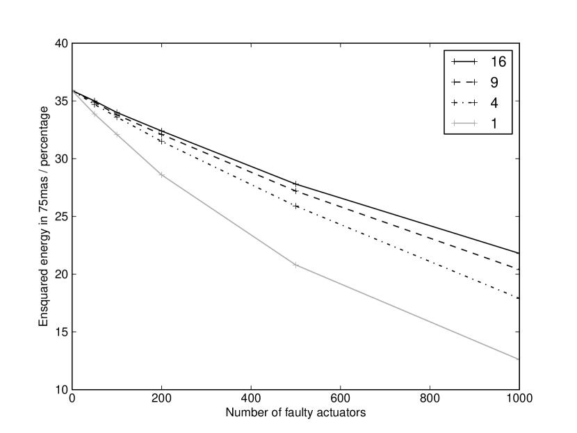
We consider the case where individual actuators are faulty, and where clumps of actuators are faulty, and investigate how performance is affected by the size of these clumps. From this figure, we can see that having small clumps of faulty actuators is less harmful to AO performance than having the same number of individual faulty actuators (i.e. the total number of faulty actuators is the same in each case).
For the remainder of this paper we consider only the case for individual actuators, i.e. we do not consider faulty actuators grouped together in clumps.
3.2 Actuators stuck at other surface heights
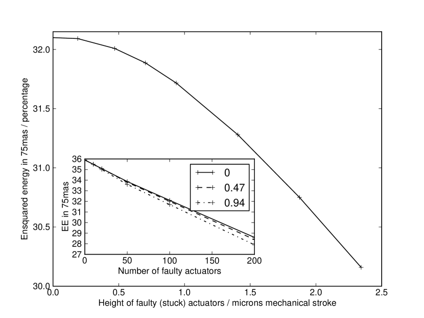
We consider the case where DM actuators are stuck at some height other than the mean phase position, for DMs both with and without limited stroke. Fig. 2 shows that there is only a slight performance dependence on the height at which actuators are stuck (for an otherwise unlimited DM) when this height is small. However, as the faulty actuator height increases, performance is degraded since these actuators have a larger impact on corrected wavefront phase. For DMs with actuators stuck at more than one surface height, we find that performance is almost identical to the case where actuators are stuck at a single height (here we consider only the case with actuators stuck at equal positive or negative surface heights).
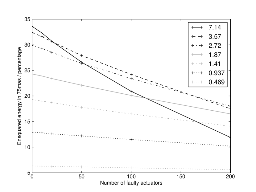
We have previously shown (Basden et al., 2013) that limited MOAO DM stroke affects AO performance, and that, as expected, DMs with larger stroke provide better performance. However, in the case of a DM with faulty actuators which are stuck at the limits of the DM surface, it is evident that large stroke will no longer give best performance, since this would result in actuators stuck at high surface heights. Rather, as shown in Fig. 3, there is a trade-off between the effect of stuck actuators, and the effect of actuator clipping on working actuators when they reach the DM stroke range. It should be noted that the optimal stroke will change under different atmospheric conditions. Worse seeing will require a larger DM stroke to avoid performance degradation, while in better seeing, if the stroke is too large then the faulty actuators will have a larger effect on performance.
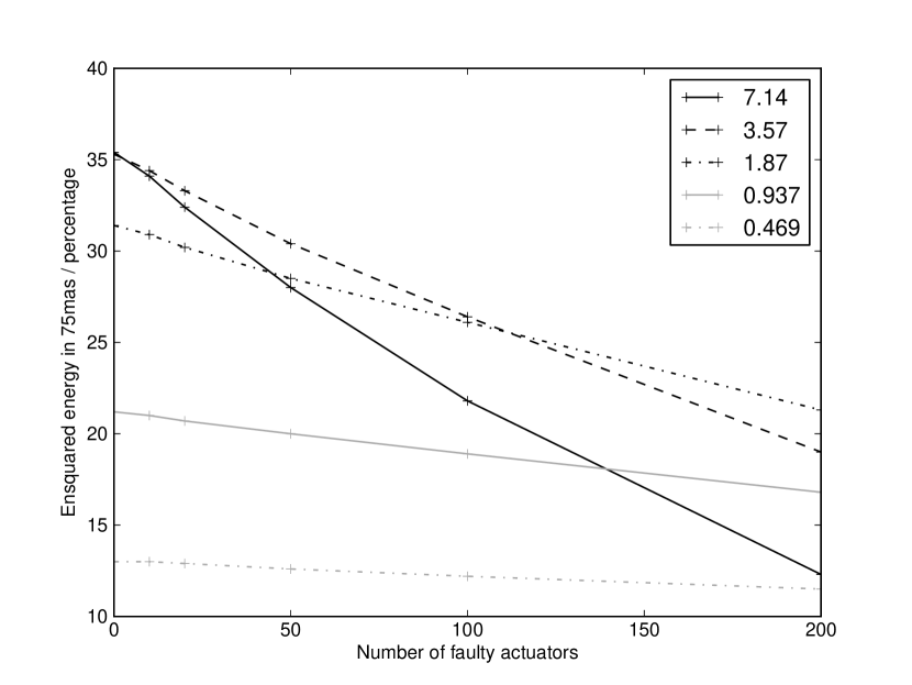
It is interesting to note that if there are 200 faulty actuators stuck at the stroke limit, then a DM with 7 m stroke will offer worse performance than one with about 1m stroke. Therefore, care should be taken when specifying maximum stroke and faulty actuator requirements. When actuators are stuck at the DM stroke limit, it should be noted that performance drops much more quickly with number of faulty actuators than when they are stuck at mid-range. We suggest that when actuators are stuck at DM stroke limits, only 10-20 actuators (about 0.2%) should be accepted before AO corrected ensquared energy falls by more than 1%.
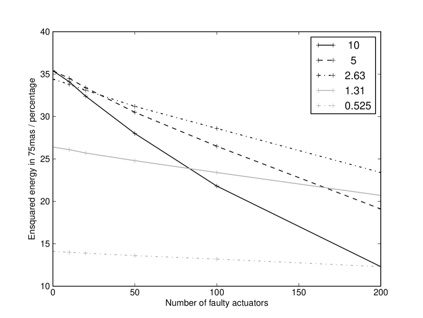
Fig. 4 shows AO performance as a function of number of faulty actuators, which are stuck at about 70% of the maximum DM stroke, which is given in the legend. This again shows that lower total DM stroke can be an advantage when faulty actuators are present, and covers the case where faulty actuators are stuck at some level not equal to the full DM stroke limits.
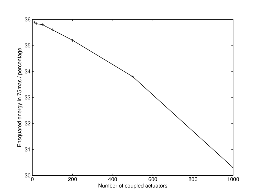
3.3 Actuator coupling
We have investigated cases where a fraction of actuators are not directly controlled, but move to the mean position of their neighbours. Fig. 5 shows AO performance as a function of number of coupled actuators. For EAGLE, there is little degradation in performance until over 100 actuators are coupled in this way, and that even when 5% of actuators are coupled, ensquared energy within 75 mas falls by less than 1%. As would be expected, having a given number of coupled actuators is far less harmful to AO performance than having the same number of stuck actuators.
3.4 Performance without the global M4 DM
We now consider (partly for completeness, partly for risk mitigation) the case where the E-ELT M4 DM is not used for AO correction. Therefore, the MOAO DMs must provide all of the correction. Fig. 6 shows performance as a function of number of actuators stuck at the DM stroke limit, for DMs with different total stroke capability.
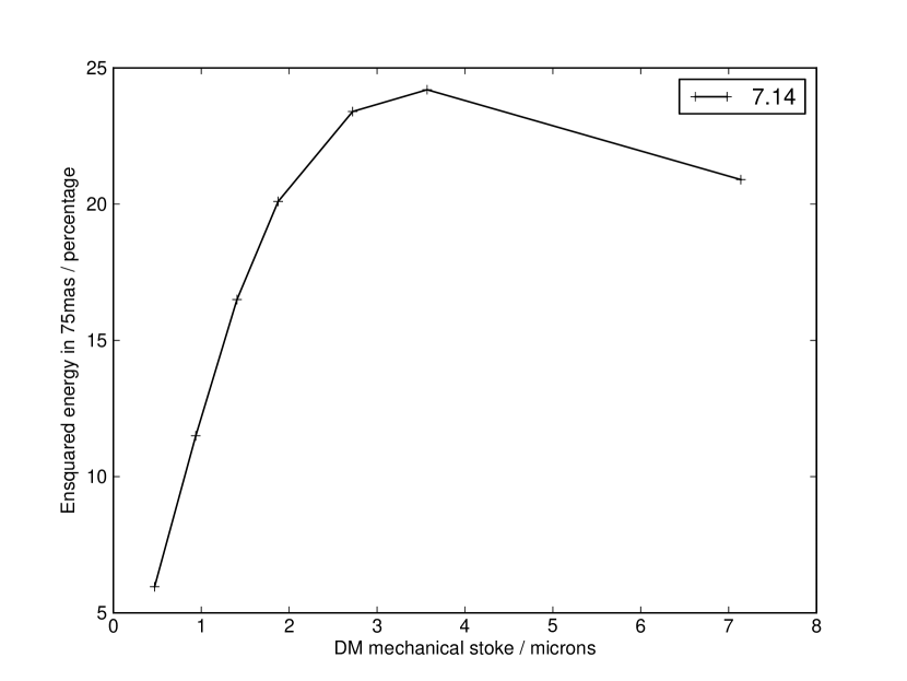
It can be seen that when there are no faulty actuators, best performance is obtained when DM stroke is large, as expected. However, when stroke is large, AO performance falls faster once the number of faulty actuators increases. This is an important consideration for AO system designers: If it is expected that there will be a number of faulty actuators, stuck at the stroke limits of the DM, then it may be better to choose a DM with reduced stroke. As can be seen from Fig. 7, if there are 100 faulty actuators, a DM with stroke limited to 2.7 m or 3.5 m gives better performance than one limited to about 7 m.
The explanation for this is simple: An increased number of faulty actuators will result in increased phase distortion if these actuators are stuck further from mean position, worsening performance.
In the case where all actuators are stuck in one direction (i.e. all high, or all low), rather than having some actuators stuck high, and some stuck low, some risk mitigation can be made with a large stroke DM, by altering the defined mid-point, i.e. by moving the DM zero-point closer to the stroke limits at which the actuators are stuck. This effectively clips the DM more stringently in one direction. In this case, a DM with higher stroke will always yield better performance. However, this can come at the expense of some complexity, since DMs are not always as well behaved further from their mid-point, and can have linearity and surface flatness issues.
3.5 Modelling of a known faulty actuator map
To add a degree of realism to our simulations, we consider the case of the dead actuator map for an existing actuator DM, that is used by the Gemini Planet Imager instrument (Macintosh et al., 2012). This map includes actuators that are stuck in both directions, and also actuators that are coupled to nearest neighbours. A total of 23 actuators were coupled (about 0.5% of all available actuators), five stuck high and three stuck low (a total of about 0.2% of available actuators). At this level, we find that AO performance is almost no different from when using a perfect DM, as can be expected by considering cases in previous sections with similar numbers of faulty actuators.
It is likely that for an ELT instrument such as EAGLE, a larger number of faulty actuators than this will be present, since the requirement for a large number of DMs at low cost means that imperfections may have to be accepted unless there are improvements in DM manufacturing techniques. It is not unknown for DM actuators to fail with age, which will also increase the numbers of faulty actuators. However, as the results in previous sections show, the performance of ELT instruments such as EAGLE only becomes significantly affected when 1–2% of actuators, or more in the case of coupled actuators (up to 5%), are faulty. The EAGLE instrument can therefore cope with a larger fraction of faulty actuators than evident on an existing DM, allowing some of the risk associated with EAGLE to be removed.
We have discussed cost reductions due to accepting increased numbers of faulty actuators with a leading DM manufacturer, and such reductions would be possible, though we do not discuss this further here.
4 Conclusions
We have made a study of the effect of faulty DM actuators on ELT-scale MOAO performance using an end-to-end Monte-Carlo simulation tool. Individual DM actuators that are stuck at some level relative to the mean surface position have been considered, as well as actuators which are coupled to nearest neighbours. For the instrument description considered here, we find that between 1–2% of actuators can be faulty (stuck at mid-range) before significant performance degradation (of more than a 1–2% drop in ensquared energy) occurs. When actuators are stuck at the stroke limit of the DM, the requirements are more stringent, with only 0.2% of actuators allowed to be faulty before ensquared energy drops by more than 1%. We find that care should be taken when specifying maximum DM stroke if it is known that faulty (stuck) actuators will be present.
For actuators that a coupled to nearest neighbours, a greater fraction, up to about 5%, can be faulty before AO performance begins to be affected. It should be noted that more stringent requirements will be needed for instruments demanding higher AO performance, such as laser tomographic adaptive optics (LTAO) or extreme adaptive optics (XAO) systems.
These findings allow the risk and cost for an instrument such as EAGLE to be significantly reduced, and can be applied to any instrument requiring a large number of high order DMs that are currently at the cutting edge of technological innovation.
Acknowledgements
This work is funded by the UK Science and Technology Facilities Council, grant ST/K003569/1.
References
- Babcock (1953) Babcock H. W., 1953, Pub. Astron. Soc. Pacific, 65, 229
- Basden et al. (2013) Basden A. G., Bharmal N. A., Myers R. M., Morris S. L., Morris T. J., 2013, MNRAS, 435, 992
- Basden et al. (2007) Basden A. G., Butterley T., Myers R. M., Wilson R. W., 2007, Appl. Optics, 46, 1089
- Cornelissen et al. (2006) Cornelissen S. A., Bierden P. A., Bifano T. G., , 2006, Development of a 4096 element MEMS continuous membrane deformable mirror for high contrast astronomical imaging
- Le Louarn et al. (2012) Le Louarn M., Clare R., Béchet C., Tallon M., 2012 Vol. 8447, Simulations of adaptive optics systems for the e-elt. pp 84475D–84475D–7
- Macintosh et al. (2012) Macintosh B. A., Anthony A., Atwood J., Barriga N., Bauman B., Caputa K., Chilcote J., Dillon D., Doyon R., Dunn J., Gavel D. T., Galvez R., Goodsell S. J., 2012, in Society of Photo-Optical Instrumentation Engineers (SPIE) Conference Series Vol. 8446 of Society of Photo-Optical Instrumentation Engineers (SPIE) Conference Series, The Gemini Planet Imager: integration and status
- Norton et al. (2009) Norton A., Evans J. W., Gavel D., Dillon D., Palmer D., Macintosh B., Morzinski K., Cornelissen S., , 2009, Preliminary characterization of Boston Micromachines’ 4096-actuator deformable mirror
- Rousset et al. (2010) Rousset G., Fusco T., Assemat F., Gendron E., Morris T., Robert C., Myers R. a., 2010, in Society of Photo-Optical Instrumentation Engineers (SPIE) Conference Series Vol. 7736 of Society of Photo-Optical Instrumentation Engineers (SPIE) Conference Series, EAGLE MOAO system conceptual design and related technologies. pp 77360S–77360S–11