How Many Beamforming Vectors Generate the Same Beampattern?
Abstract
In this letter, we address the fundamental question of how many beamforming vectors exist which generate the same beampattern? The question is relevant to many fields such as, for example, array processing, radar, wireless communications, data compression, dimensionality reduction, and biomedical engineering. The desired property of having the same beampattern for different columns of a beamspace transformation matrix (beamforming vectors) often plays a key importance in practical applications. The result is that at most beamforming vectors with the same beampattern can be generated from any given beamforming vector. Here is the dimension of the beamforming vector. At the constructive side, the answer to this question allows for computationally efficient techniques for the beamspace transformation design. Indeed, one can start with a single beamforming vector, which gives a desired beampattern, and generate a number of other beamforming vectors, which give absolutely the same beampattern, in a computationally efficient way. We call the initial beamforming vector as the mother beamforming vector. One possible procedure for generating all possible new beamforming vectors with the same beampattern from the mother beamforming vector is proposed. The application of the proposed analysis to the transmit beamspace design in multiple-input multiple-output radar is also given.
Index Terms:
Array processing, beamforming, beampattern design, dimensionality reduction, multiple-input multiple-output (MIMO) radar.I Introduction
Beamspace transformation [1], [2] and beamforming [3] techniques are the key approaches, among others, in array signal processing [4]-[6], radar [7], multiple-input multiple-output (MIMO) radar [8]-[21], wireless communications [22]-[24], data compression and dimensionality reduction [25]-[27], biomedical engineering [28], etc.
In the traditional applications in array processing and dimensionality reduction, it is often desirable to reduce the high dimensional space into a lower one by means of the beamspace transformations. In more recent applications to MIMO radar, it has been required not only to design a lower dimensional transmit beamspace but also to transmit a number of orthogonal waveforms from a larger number of transmit antenna elements while achieving transmit coherent processing gain. While designing such a transmit beamspace, certain properties have to be satisfied such as a uniform power distribution for different transmit waveforms in the desired sector where the targets are likely to be located [19]. The latter enables, for example, to enforce at the transmitter the very useful rotational invariance property [29], [30] which can significantly simplify and improve, for example, the direction-of-arrival (DOA) estimation techniques used at the receive antenna array.
From a practical point of view, generating a transmit beamspace that satisfies a number of properties is very desirable. Thus, it is of interest to look for simple design techniques allowing to start with a single beamforming vector, which we call the mother beamforming vector by analogy with mother wavelet [31] in wavelet analysis, and generate a number of other beamforming vectors that all have the same beampattern as the mother beamforming vector. Beamforming vectors that possibly satisfy some additional practically important properties can then be selected from a set of so generated beamforming vectors. In wavelets, self-similarity is an important property where basis functions are all obtained from a single prototype mother wavelet using scaling and translation. It is interesting that a similar property exists also in the beamspace design problem. To the best of the authors knowledge, this property has not been known or exploited before.
The contributions of this letter are as following.
-
•
We first address the fundamental question of how many beamforming vectors which generate the same beampattern as the mother beamforming vector exist.
-
•
At the constructive side, we develop a computationally efficient technique for generating all such beamforming vectors.
-
•
The application of the proposed analysis to the transmit beamspace design in MIMO radar is also given.
The rest of the letter is organized as follows. The main results on the number of beamforming vectors, which have the same beampattern as the mother beamforming vector, and on the procedure of constructing such beamforming vectors are given in Section II. Section III is devoted to the application of the proposed analysis to the transmit beamspace design in MIMO radar, which aims at demonstrating the practical usefulness of the results obtained in Section II. The letter is completed with conclusion.
II Main Results
Let us consider a uniform linear array (ULA) with antenna elements. The steering vector of the array towards direction is denoted as . The transmit array beampattern can be expressed as
| (1) |
where is a beamforming vector, , and and stand for the Euclidian norm of a vector and conjugation, respectively. Let the beampattern corresponding to a given beamforming vector , referred to as the mother beamforming vector, satisfies certain shape design requirements, but it does not satisfy other practically important requirements. Such a requirement is, for example, a uniform power distribution across the antenna elements. The question then arises about existence of other distinct beamforming vectors which generate the same exact beampattern as the mother beamforming vector and which in addition satisfy other possible design requirements. The following theorem states the total number of distinct beamforming vectors with the same exact beampattern as the mother beamforming vector .
Theorem 1 : For an arbitrary transmit beamforming vector that corresponds to a ULA of size , there are at most other different beamforming vectors which have the same exact beampattern as . A constructive solution for obtaining all possible beamforming vectors is given in the proof.
Proof : Let and be two beamforming vectors with the exact same transmit beampattern. The latter implies that
| (2) |
where the matrix is defined as . It can be easily verified that the matrix has Toeplitz structure.
In the rest of this proof, we will refer to the descending diagonals of a matrix from left to right as the first, second, and up to th off-diagonal, respectively. For the notation simplicity, let us define the following vector
| (3) |
whose th element is equal to th off-diagonal elements of . Moreover, we will express the Toeplitz matrix with the diagonal and off-diagonal elements defined in as where is an operator which generates a Toeplitz matrix.
Since equation (2) holds valid in all directions, the following set of equations can be resulted by fixing to an arbitrary set of angles dented as
| (4) |
By linearly combining the set of equations in (4) using an arbitrary set of coefficients denoted as , the following equality can be concluded
| (5) |
In what follows, we will show that by the proper selection of the coefficients and angles , it is possible to make all the off-diagonal and diagonal elements of the new Toeplitz matrix equal to zero except for a desired one.
First, note that the new Toeplitz matrix can be expressed as . Based on the latter observation, we conclude that all the off-diagonal elements of the matrix are equal to zero except for th off-diagonal element if and only if all the elements of the vector are equal to zero except for the th one. Therefore, let us consider the following set of linear equations
| (6) |
where and is the unit vector whose th element is equal to one. Since the newly defined matrix has the Vandermonde structure, it is invertible under the condition that the angles are chosen to be distinct.
In what follows, it is assumed that
| (7) |
and, thus, is invertible. Therefore, by selecting the coefficient vector in (6) as , the vector can be set equal to . It implies that in terms of the aforementioned selection of the coefficient vector and angles , it is possible to make all the off-diagonal and diagonal elements of the new Toeplitz matrix equal to zero except for the th one. Using (5) and selecting , it can be resulted that which, in turn, implies that
| (8) |
The set of equations in (8) can equivalently be expressed as follows
| (9) | |||
| (10) | |||
| (11) | |||
| (12) | |||
| (13) |
Since any arbitrary Toeplitz matrix can be constructed by linearly combining the matrices , equivalently, it can be concluded that by linearly combining the equations (9)–(13), the equation (2) can be resulted. Thus, the beamforming vectors and have the same transmit beampattern if and only if the equations (9)–(13) are satisfied.
For a mother beamforming vector , we can construct the set of all possible beamforming vectors that have the same beampattern as through solving the equations (9)–(13). For this goal, let us define the following two functions of a single variable
| (14) | |||||
| (15) |
By expanding the multiplicative terms in the definitions of and , it can be verified that the equations (9)–(13) hold true if and only if is equal to . Let be a non-zero root of the first multiplicative term in the definition of , i.e., . Then it is simple to verify that is also a root of the second multiplicative term of . One implication of this observation is that the inverse conjugate of every root of is also a root of and, therefore, the roots of can be denoted as and and can be decomposed as
| (16) | |||||
Furthermore, it is easy to verify that the product can be equivalently expressed as
| (17) |
Note that the product terms and that appear in (16) preserve the structure of the first and second multiplicative terms in the definition of ( see (14)) for any arbitrary . Based on these observations, can be decomposed as the multiplication of two terms in the form of and in different ways depending on whether (or ) is the root of the first polynomial. The corresponding coefficients of the first multiplicative term in each decomposition correspond to a new beamforming vector dented as which has the same exact beampattern as . This completes the proof.
III Application to Transmit Beamspace Design in MIMO Radar
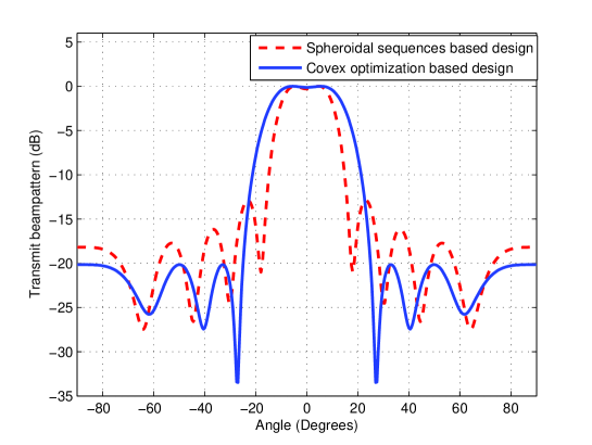
Consider a MIMO radar with transmit ULA of antennas spaced half a wavelength apart. The total transmit power is normalized to . Two mother transmit beamforming weight vectors are designed to focus the transmit energy within the sector . The first mother beamforming weight vector is designed using spheroidal sequences [2], [19]. Specifically, it is computed as , where and are the two principle eigenvectors of the matrix . The second mother beamforming weight vector is designed using convex optimization to control the sidelobe levels. In particular, it is obtained by solving the following convex optimization problem [19]
| (18) | |||
| (19) |
where combines a continuum of all out-of-sector directions, i.e., directions lying outside the sector-of-interest ; is the desired transmit phase profile of user choice; and is the parameter of the user choice that characterizes the worst acceptable level of transmit power radiation in the out-of-sector region . The phase and the parameter are chosen, i.e, the sidelobe levels are kept below dB. The mother beamforming weight vector obtained by solving the problem (18)–(19) is referred to hereafter as . The transmit beampatterns associated with mother beamforming weight vectors and are shown as the dotted and solid curves in Fig. 1, respectively.
The mother weight vector is used to generate a population of weight vectors (including ) of dimension . To implement a MIMO radar system with four orthogonal transmit waveforms, the four beamforming weight vectors among the population that achieve the best transmit power distribution across the transmit array elements are chosen. The mother weight vector and the four chosen weight vectors denoted as are given in Table 1. Since the sector is symmetric around 0, the mother beamforming vectors are real-valied. The four chosen vectors are scaled such that .
It is worth noting that each of the four chosen vectors has the same beampattern as the mother beamforming vector except for the magnitude scaling factor of . Note that the beampattern magnitude in the mainlobe as well as in the sidelobe regions is scaled by the same scaling factor, i.e., the relative attenuation of the sidelobes with respect to the mainlobe remains unchanged. The transmit power distribution across the transmit array elements for the mother transmit beamforming weight vector operated in the SIMO radar mode and the four chosen weight vectors operated in the MIMO radar mode are shown in Fig. 2. It can be seen from the figure that the
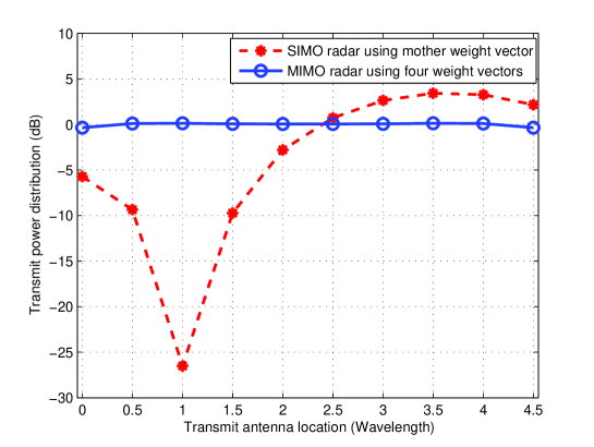
Table 1: Spheroidal sequences based mother transmit beamforming
vector and a subset of four vectors chosen from the
population.
| 0.5178 | 0.2589 | 0.2740 - 0.0000i | 0.6061 - 0.0000i | 0.6414 |
| 0.3408 | 0.1704 | 0.1980 + 0.0255i | 0.6490 - 0.0563i | 0.7281 |
| 0.0472 | 0.0236 | 0.0251 + 0.0475i | 0.6791 - 0.1247i | 0.7415 |
| -0.3263 | -0.1632 | -0.2122 + 0.0311i | 0.6797 - 0.1491i | 0.6770 |
| -0.7253 | -0.3627 | -0.4458 - 0.0317i | 0.6098 - 0.1087i | 0.5437 |
| -1.0873 | -0.5437 | -0.6098 - 0.1087i | 0.4458 - 0.0317i | 0.3627 |
| -1.3540 | -0.6770 | -0.6797 - 0.1491i | 0.2122 + 0.0311i | 0.1632 |
| -1.4830 | -0.7415 | -0.6791 - 0.1247i | -0.0251 + 0.0475i | -0.0236 |
| -1.4562 | -0.7281 | -0.6490 - 0.0563i | -0.1980 + 0.0255i | -0.1704 |
| -1.2828 | -0.6414 | -0.6061 - 0.0000i | -0.2740 + 0.0000i | -0.2589 |
mother beamforming weight vector has very poor transmit power distribution. For example, the power radiated by the third transmit array element is over 25 dB less than the average transmit power per transmit array element. On the other hand, the four chosen beamforming vectors exhibit transmit power distribution that is almost uniform, which is desirable in practice.
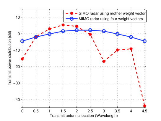
Similarly, the mother weight vector is used to
generate a population of beamforming vectors
(including ) which have the exact same
beampattern. The four beamforming weight vectors among the
population that achieve the best transmit power distribution across
the transmit array elements are chosen. The mother weight vector
and the four chosen weight vectors denoted
as are given in Table 2. The
transmit power distributions across the transmit array elements for
the mother weight vector and the four chosen weight vectors are
shown in Fig. 3. It can be seen from the figure that the
four chosen vectors yield much better transmit power distribution
as compared to the mother weight vector.
Table 2: Convex optimization based mother transmit beamforming vector
and a subset of four vectors chosen from the population.
| -0.1702 | 0.0011 | 0.0005 | 0.5412 | 0.2438 |
| 0.8093 | -0.0661 | -0.0303 | 0.7829 | 0.0930 |
| 1.4003 | 0.2481 | 0.1432 | 0.9311 | -0.1178 |
| 1.8485 | 0.6505 | 0.1931 | 0.7435 | -0.6407 |
| 1.6711 | 0.8511 | 0.0333 | 0.3386 | -0.8910 |
| 0.9506 | 0.8910 | -0.3386 | -0.0333 | -0.8511 |
| 0.1437 | 0.6407 | -0.7435 | -0.1931 | -0.6505 |
| -0.3186 | 0.1178 | -0.9311 | -0.1432 | -0.2481 |
| -0.3459 | -0.0930 | -0.7829 | 0.0303 | 0.0661 |
| 0.0063 | -0.2438 | -0.5412 | -0.0005 | -0.0011 |
IV Conclusion
The important question regarding the existence of other beamforming vectors whose transmit beampatterns are the exact same as the transmit beampattern of a given beamforming vector has been addressed. It has been proven that at most other beamforming vectors with the same beampattern can be generated from any given beamforming vector. The method for constructing the set of all possible beamforming vectors from a given mother beamforming vector has been also developed. Moreover, it has been shown how this result can be utilized in the actively developing field of transmit beamspace design for MIMO radar systems, where it is desirable to have different transmit waveforms to be radiated with the same transmit beampattern.
References
- [1] S. Anderson, “On optimal dimension reduction for sensor array signal processing,” Signal Processing, vol. 30, pp. 245–256, Jan. 1993.
- [2] P. Forster and G. Vezzosi, “Application of spheroidal sequences to array processing,” in Proc. IEEE Int. Conf. Acoustics, Speech, Signal Processing, Dallas, TX, May 1987, pp. 2268–2271.
- [3] S. A. Vorobyov, “Adaptive and robust beamforming,” in Academic Press Library in Signal Processing, Vol. 3, Array and Statistical Signal Processing, Eds. R. Chellappa and S. Theodoridis, Academic Press, 2014, pp. 503–552.
- [4] H. L. Van Trees, Optimum Array Processing. NewYork: Wiley, 2002.
- [5] A. B. Gershman, “Direction finding using beamspace root estimator banks,” IEEE Trans. Signal Processing, vol. 46, no. 11, pp. 3131–3135, Nov. 1998.
- [6] M. D. Zoltowski, G. M. Kautz, and S. D. Silverstein, “Beamspace root-MUSIC,” IEEE Trans. Signal Processing, vol. 41, no. 1, pp. 344–364, Jan. 1993.
- [7] A. Farina, Antenna Based Signal Processing Techniques for Radar Systems. Norwood, MA: Artech House, 1992.
- [8] D. R. Fuhrmann and G. San Antonio, “Transmit beamforming for MIMO radar systems using partial signal correlation,” in Proc. Asilomar Conf. Signals, Syst., Comput., Asilomar, CA, USA, Nov. 2004, pp. 295–299.
- [9] P. Stoica, J. Li, and Y. Xie, “On probing signal design for MIMO radar,” IEEE Trans. Signal Processing, vol. 55, no. 8, pp. 4151–4161, Aug. 2007.
- [10] D. R. Fuhrmann and G. San Antonio, “Transmit beamforming for MIMO radar systems using signal cross-correlation,” IEEE Trans. Aerospace and Electronic Systems, vol. 44, pp. 171–186, Jan. 2008.
- [11] C.-Y. Chen and P. Vaidyanathan, “MIMO radar space-time adaptive processing using prolate spheroidal wave functions,” IEEE Trans. Signal Processing, vol. 56, no. 2, pp. 623–635, Feb. 2008.
- [12] J. P. Browning, D. R. Fuhrmann, and M. Rangaswamy, “A hybrid MIMO phased-array concept for arbitrary spatial beampattern synthesis,” in Proc. IEEE Digital Signal Processing Signal Processing Education Workshop (DSP/SPE), Marco Island, FL, Jan. 2009, pp. 446–450.
- [13] D. R. Fuhrmann, P. Browning, and M. Rangaswamy, “Constant-modulus partially correlated signal design for uniform linear and rectangular MIMO radar arrays,” in Proc. 4th Int. Conf. Waveform Diversity Design (WDD), Orlando, FL, Feb. 2009, pp. 197–201.
- [14] A. Hassanien and S. A. Vorobyov, “Transmit/receive beamforming for MIMO radar with colocated antennas,” in Proc. IEEE Int. Conf. Acoustic, Speech, Signal Processing (ICASSP), Taipei, Taiwan, Apr. 2009, pp. 2089-2092.
- [15] A. Hassanien and S. A. Vorobyov, “Direction finding for MIMO radar with colocated antennas using transmit beamspace preprocessing,” in Proc. 3rd IEEE Inter. Workshop Computational Advances in Multi-Sensor Adaptive Processing, Aruba, Dutch Antilles, Dec. 2009, pp. 181–184.
- [16] T. Aittomaki and V. Koivunen, “Beampattern optimization by minimization of quartic polynomial,” in Proc. 15 IEEE/SP Statist. Signal Processing Workshop, Cardiff, U.K., Sep. 2009, pp. 437–440.
- [17] D. R. Fuhrmann, P. Browning, and M. Rangaswamy, “Signaling strategies for the hybrid MIMO phased-array radar,” IEEE J. Sel. Topics Signal Processing, vol. 4, no. 1, pp. 66–78, Feb. 2010.
- [18] A. Hassanien and S. A. Vorobyov, “Phased-MIMO radar: A tradeoff between phased-array and MIMO radars,” IEEE Trans. Signal Processing, vol. 58, no. 6, pp. 3137–3151, June 2010.
- [19] A. Hassanien and S. A. Vorobyov, ”Transmit energy focusing for DOA estimation in MIMO radar with colocated antennas,” IEEE Trans. Signal Processing, vol. 59, no. 6, pp. 2669–2682, June 2011.
- [20] A. Hassanien and S. A. Vorobyov, “Subspace-based direction finding using transmit energy focusing in MIMO radar with colocated antennas,” in Proc. IEEE Int. Conf. Acoust., Speech, Signal Processing, Prague, Czech Republic, May 2011, pp. 2788–2791.
- [21] A. Khabbazibasmenj, S. A. Vorobyov, and A. Hassanien, “Transmit beamspace design for direction finding in colocated MIMO radar with arbitrary receive array,” in Proc. 36th IEEE Inter. Conf. Acoustics, Speech, and Signal Processing, Prague, Czech Republic, May 2011, pp. 2784–2787.
- [22] D. Tse and P. Viswanath, Fundamentals of Wireless Communication. Cambridge University Press, 2005.
- [23] A. Goldsmith, Wireless Communications. Cambridge University Press, 2005.
- [24] A. F. Molisch, Wireless Communications. John Wiley and Sons, 2010.
- [25] Y. Jieping, L. Qi, X. Hui, H. Park, R. Janardan, and V. Kumar, “IDR/QR: An incremental dimension reduction algorithm via QR decomposition,” IEEE Trans. Knowl. Data Eng., vol. 19, no. 9, pp. 1208–1222, Sep. 2005.
- [26] L. Haiping, K. Plataniotis, and A. Venetsanopoulos, “MPCA: Multilinear principal component analysis of tensor objects,” IEEE Trans. Neural Networks, vol. 19, no. 1, pp. 18–39, Jan. 2008.
- [27] A. Hassanien and S. A. Vorobyov, “A robust adaptive dimension reduction technique with application to array processing,” IEEE Signal Processing Letters, vol. 16, no. 1, pp. 22-25, Jan. 2009.
- [28] A. Rodriguez-Rivera, B. Baryshnikov, B. Van Veen, and R. Wakai, “MEG and EEG source localization in beamspace,” IEEE Trans. Biomedical Engineering, vol. 53, no. 3, pp. 430–341, Mar. 2006.
- [29] R. Roy and T. Kailath, “ESPRIT estimation of signal parameters via rotational invariance techniques,” IEEE Trans. Acoustic, Speech, Signal Processing, vol. 37, no. 7, pp. 984–995, Jul. 1989.
- [30] A. Khabbazibasmenj, A. Hassanien, S. A. Vorobyov, and M. W. Morency, “Efficient transmit beamspace design for search-free based DOA estimation in MIMO radar,” IEEE Trans. Signal Processing, vol. 62, to be published in 2014. (http://arxiv.org/abs/1305.4979)
- [31] M. Vetterli and J. Kovacevic. Wavelets and Subband Coding. Vol. 87. Englewood Cliffs, New Jersey: Prentice Hall PTR, 1995.