Generalized Signal Alignment For MIMO Two-Way X Relay Channels

Kangqi Liu, Meixia Tao, Zhengzheng Xiang and Xin Long Dept. of Electronic Engineering, Shanghai Jiao Tong University, Shanghai, China
Emails: {forever229272129, mxtao, 7222838, lx_yokumen}@sjtu.edu.cn
Abstract

We study the degrees of freedom (DoF) of MIMO two-way X relay channels. Previous work studied the case N<2M𝑁2𝑀N<2M, where N𝑁N and M𝑀M denote the number of antennas at the relay and each source, respectively, and showed that the maximum DoF of 2N2𝑁2N is achievable when N8M5𝑁8𝑀5N\leq\lfloor\frac{8M}{5}\rfloor by applying signal alignment (SA) for network coding and interference cancelation. This work considers the case N>2M𝑁2𝑀N>2M where the performance is limited by the number of antennas at each source node and conventional SA is not feasible. We propose a generalized signal alignment (GSA) based transmission scheme. The key is to let the signals to be exchanged between every source node align in a transformed subspace, rather than the direct subspace, at the relay so as to form network-coded signals. This is realized by jointly designing the precoding matrices at all source nodes and the processing matrix at the relay. Moreover, the aligned subspaces are orthogonal to each other. By applying the GSA, we show that the DoF upper bound 4M4𝑀4M is achievable when M2N5𝑀2𝑁5M\leq\lfloor\frac{2N}{5}\rfloor (M𝑀M is even) or M2N15𝑀2𝑁15M\leq\lfloor\frac{2N-1}{5}\rfloor (M𝑀M is odd). Numerical results also demonstrate that our proposed transmission scheme is feasible and effective.

This work is supported by the National 973 project under grant 2012CB316100 and by the NSF of China under grants 61322102 and 61329101.

I Introduction

Wireless relay has been an important ingredient in both ad hoc and infrastructure-based wireless networks. It shows great promises in power reduction, coverage extension and throughput enhancement. In the simplest scenario, a relay node only serves a single user. This forms the classic one-way relaying and the relay strategies are maturing. With the rapid expansion of multi-user communications, a relay has become very much like a wireless gateway where multiple users communicate with each other via a common relay. A fundamental question that arises is what is the maximum number of data streams that can be transmitted and how to achieve it. This leads to the analysis of degrees of freedom (DoF) and also drives the development of more advanced relay strategies for efficient relay-assisted multi-user communication.

The recently proposed two-way relaying is such an advanced relay method that offers high spectral efficiency in a system where two users exchange information with each other through a relay [1]. The key idea is to apply physical layer network coding (PLNC) at the relay end [2] [3]. With PLNC, the maximum achievable DoF of the MIMO two-way relay channel is 2min{M,N}2𝑀𝑁2\min\{M,N\} [4], where M𝑀M and N𝑁N denote the number of antennas at each source node and the relay, respectively. When there are three or more users exchanging information with each other via a common relay, PLNC is not enough to achieve the DoF of the network.

Based on the idea of interference alignment[5] [6], another promising technique, signal alignment (SA) is firstly proposed in [7] to analyze the maximum achievable DoF for MIMO Y channel, where three users exchange independent messages with each other via a relay. By jointly designing the precoders at each source node, SA is able to align the signals from two different source nodes in a same subspace of the relay node. By doing so, the two data streams to be exchanged between a pair of source codes are combined into one network-coded symbol and thus the relay can forward more data streams simultaneously. It is proved that with SA for network-coding and network-coding aware interference nulling the theoretical upper bound 3M3𝑀3M of DoF is achievable when N3M2𝑁3𝑀2N\geq\lceil\frac{3M}{2}\rceil [8]. Here, again, M𝑀M and N𝑁N denote the number of antennas at each source node and the relay node, respectively. The extension to K-user MIMO Y Channels is considered in [9].

In [10], SA is applied in MIMO two-way X relay channel, where there are two groups of source nodes and one relay node, and each of the two source nodes in one group exchange independent messages with the two source nodes in the other group via the relay node. It is shown that the DoF upper bound is 2min{2M,N}22𝑀𝑁2\min\{2M,N\}, and the upper bound 2N2𝑁2N is achievable when N8M5𝑁8𝑀5N\leq\lfloor\frac{8M}{5}\rfloor by applying SA and interference cancelation.

In this paper, we are interested in the ability of the DoF upper bound 4M4𝑀4M for MIMO two-way X relay channel in the case N>2M𝑁2𝑀N>2M, where the performance is limited only by the number of antennas at each source. It is worth mentioning that SA is not feasible under the antenna configuration N2M𝑁2𝑀N\geq 2M. The reason is as follows. Recall that SA condition is

𝐇1,r𝐯1=𝐇2,r𝐯2,subscript𝐇1𝑟subscript𝐯1subscript𝐇2𝑟subscript𝐯2{\bf H}_{1,r}{\bf v}_{1}={\bf H}_{2,r}{\bf v}_{2}, (1)

where 𝐇isubscript𝐇𝑖{\bf H}_{i} is an N×M𝑁𝑀N\times M matrix (corresponding to the channel matrix from source i𝑖i to relay) and 𝐯isubscript𝐯𝑖{\bf v}_{i} is an M×1𝑀1M\times 1 vector (corresponding to the beamforming vector of source i𝑖i). The above alignment condition can be rewritten as

[𝐇1,r𝐇2,r][𝐯1𝐯2]=0.delimited-[]subscript𝐇1𝑟subscript𝐇2𝑟delimited-[]subscript𝐯1missing-subexpressionmissing-subexpressionsubscript𝐯2missing-subexpressionmissing-subexpression0\left[{\bf H}_{1,r}~{}~{}-{\bf H}_{2,r}\right]\left[\begin{array}[]{ccc}{\bf v}_{1}\\ {\bf v}_{2}\\ \end{array}\right]=0. (2)

Clearly, for (2) to hold, one must N<2M𝑁2𝑀N<2M, or equivalently M>N2𝑀𝑁2M>\frac{N}{2}.

To achieve the maximum DoF at MN2𝑀𝑁2M\leq\frac{N}{2}, we propose a new transmission scheme, named generalized signal alignment (GSA). Compared with the existing SA, the proposed GSA has the following major difference. The signals to be exchanged do not align directly in the subspace observed by the relay. Instead, they are aligned in a transformed subspace after certain processing at the relay, which is orthogonal to each other. This is done by jointly designing the precoding matrices at the source nodes and the processing matrix at the relay node. With the proposed GSA, we show that the total DoF upper bound 4M4𝑀4M of MIMO two-way X relay channel is achievable when M2N5𝑀2𝑁5M\leq\lfloor\frac{2N}{5}\rfloor(M𝑀M is even) or M2N15𝑀2𝑁15M\leq\lfloor\frac{2N-1}{5}\rfloor(M𝑀M is odd).

The remainder of the paper is organized as follows. In Section II, we introduce the system model of the MIMO two-way X relay channel. In Section III, we introduce the GSA transmission scheme with a motivate example. In Section IV, we analyze the achievability of the DoF upper bound when M<N2𝑀𝑁2M<\frac{N}{2}. In Section V, we show our numerical results. Section VI presents concluding remarks.

Notations: ()Tsuperscript𝑇(\cdot)^{T}, ()Hsuperscript𝐻(\cdot)^{H} and ()superscript(\cdot)^{{\dagger}} denote the transpose, Hermitian transpose and the Moore-Penrose pseudoinverse, respectively. ε[]𝜀delimited-[]\varepsilon[\cdot] stands for expectation. |𝐱|𝐱|{\bf x}| means 2-norm of vector 𝐱𝐱{\bf x}. span(𝐇)span𝐇\mbox{span}({\bf H}) and null(𝐇)null𝐇{\mbox{null}({\bf H})} stand for the column space and the null space of the matrix 𝐇𝐇{\bf H}, respectively. dim(𝐇)dim𝐇\mbox{dim}({\bf H}) denotes the dimension of the column space of 𝐇𝐇{\bf H}. 𝐱delimited-⟨⟩𝐱\langle{\bf x}\rangle denotes normalization operation on vector 𝐱𝐱{\bf x}, i.e.𝐱=𝐱|𝐱|delimited-⟨⟩𝐱𝐱𝐱\langle{\bf x}\rangle=\frac{\bf x}{|\bf x|}. x𝑥\lfloor x\rfloor denotes the largest integer no greater than x𝑥x. x𝑥\lceil x\rceil denotes the smallest integer no less than x𝑥x. I is the identity matrix.

II System Model

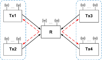
We consider the same MIMO two-way X relay channel as in [10] and shown in Fig. 1. It consists of two groups of source nodes, each equipped with M𝑀M antennas, and one relay node, equipped with N𝑁N antennas. Each source node exchanges independent messages with each source node in the other group with the help of the relay. The independent message transmitted from source i𝑖i to source j𝑗j is denoted as Wijsubscript𝑊𝑖𝑗W_{ij}. At each time slot, the message is encoded into a dij×1subscript𝑑𝑖𝑗1d_{ij}\times 1 symbol vector 𝐬ijsubscript𝐬𝑖𝑗{\bf s}_{ij}, where dijsubscript𝑑𝑖𝑗d_{ij} denotes the number of independent data flows from source i𝑖i to source j𝑗j.

Taking source node 111 for example, the transmitted signal vector 𝐱1subscript𝐱1{\bf x}_{1} from source node 111 is given by

𝐱1=𝐕13𝐬13+𝐕14𝐬14=𝐕1𝐬1,subscript𝐱1subscript𝐕13subscript𝐬13subscript𝐕14subscript𝐬14subscript𝐕1subscript𝐬1\displaystyle{\bf x}_{1}={\bf V}_{13}{\bf s}_{13}+{\bf V}_{14}{\bf s}_{14}={\bf V}_{1}{\bf s}_{1}, (3)

where s1=[s13,s14]Tsubscripts1superscriptsubscripts13subscripts14𝑇\textbf{s}_{1}=[\textbf{s}_{13},\textbf{s}_{14}]^{T}, V1=[V13,V14]subscriptV1subscriptV13subscriptV14\textbf{V}_{1}=[\textbf{V}_{13},\textbf{V}_{14}], V13subscriptV13\textbf{V}_{13} and V14subscriptV14\textbf{V}_{14} are the M×d13𝑀subscript𝑑13M\times d_{13} and M×d14𝑀subscript𝑑14M\times d_{14} precoding matrices for the information symbols to be sent to source node 3 and 4, respectively.

The communication of the total messages takes place in two phases: the multiple access (MAC) phase and the broadcast (BC) phase. In the MAC phase, all four source nodes transmit their signals to the relay. The received signal 𝐲rsubscript𝐲𝑟{\bf y}_{r} at the relay is given by

𝐲r=i=14𝐇i,r𝐱i+𝐧r,subscript𝐲𝑟superscriptsubscript𝑖14subscript𝐇𝑖𝑟subscript𝐱𝑖subscript𝐧𝑟\displaystyle{\bf y}_{r}=\sum\limits_{i=1}^{4}{\bf H}_{i,r}{\bf x}_{i}+{\bf n}_{r}, (4)

where 𝐇i,rsubscript𝐇𝑖𝑟{\bf H}_{i,r} denotes the frequency-flat quasi-static N×M𝑁𝑀N\times M complex channel matrix from source node i𝑖i to the relay and 𝐧rsubscript𝐧𝑟{\bf n}_{r} denotes the N×1𝑁1N\times 1 additive white Gaussian noise (AWGN) with variance σn2superscriptsubscript𝜎𝑛2\sigma_{n}^{2}. The entries of the channel matrix 𝐇i,rsubscript𝐇𝑖𝑟{\bf H}_{i,r} and those of the noise vector 𝐧rsubscript𝐧𝑟{\bf n}_{r}, are independent and identically distributed (i.i.d.) zero-mean complex Gaussian random variables with unit variance. Thus, each channel matrix is of full rank with probability 111.

Upon receiving 𝐲rsubscript𝐲𝑟{\bf y}_{r} in (4), the relay processes these messages to obtain a mixed signal xrsubscriptx𝑟\textbf{x}_{r}, and broadcasts to all the users. The received signal at source node i𝑖i can be written as

𝐲i=Gr,ixr+𝐧i,subscript𝐲𝑖subscriptG𝑟𝑖subscriptx𝑟subscript𝐧𝑖\displaystyle{\bf y}_{i}=\textbf{G}_{r,i}\textbf{x}_{r}+{\bf n}_{i}, (5)

where 𝐆r,isubscript𝐆𝑟𝑖{\bf G}_{r,i} denotes the frequency-flat quasi-static M×N𝑀𝑁M\times N complex channel matrix from relay to the source node i𝑖i, and nisubscriptn𝑖\textbf{n}_{i} denotes the AWGN at the node i𝑖i. Each user tries to obtain its desirable signal from its received signal using its own transmit signal as side information.

Refer to caption
Figure 1: MIMO Two-way X Relay Channel.

III Generalized Signal Alignment

In this section, we shall introduce the GSA-based transmission scheme for MIMO two-way X relay channel when M<N2𝑀𝑁2M<\frac{N}{2}. Note that for this case, the corresponding DoF upper bound is 4M4𝑀4M [10].

As a motivating example, we consider a system where each source has M=2𝑀2M=2 antennas and the relay has N=5𝑁5N=5 antennas. For this system, the proposed GSA-based transmission scheme achieves d13=d14=d23=d24=d31=d32=d41=d42=1subscript𝑑13subscript𝑑14subscript𝑑23subscript𝑑24subscript𝑑31subscript𝑑32subscript𝑑41subscript𝑑421d_{13}=d_{14}=d_{23}=d_{24}=d_{31}=d_{32}=d_{41}=d_{42}=1, yielding a total DoF of 888.

III-A MAC phase

In the MAC phase, each source node transmits the precoded signals to the relay simultaneously. Let source node 111 transmits the data streams s13subscript𝑠13s_{13} and s14subscript𝑠14s_{14} by using beamforming vectors 𝐯13subscript𝐯13{\bf v}_{13} and 𝐯14subscript𝐯14{\bf v}_{14}, respectively to source nodes 333 and 444. Similar notations are used for the other three nodes. Thus, there are totally 888 data streams arriving at the relay. We rewrite the received signal (4) as

𝐲rsubscript𝐲𝑟\displaystyle{\bf y}_{r}~{}~{}~{}~{}~{}~{}~{}~{}~{}~{}~{}~{}~{}~{}~{}~{}~{}~{}~{}~{}~{}~{}~{}~{}~{}~{}~{}~{}~{}~{}~{}~{}~{}~{}~{}~{}~{}~{}~{}~{}~{}~{}~{}~{}~{}~{}~{}~{}~{}~{}~{}~{}~{}~{}~{}~{}~{}~{}~{}~{}~{}~{}~{}
=[𝐇1,r𝐇2,r𝐇3,r𝐇4,r][𝐕1𝟎𝟎𝟎𝟎𝐕2𝟎𝟎𝟎𝟎𝐕3𝟎𝟎𝟎𝟎𝐕4][𝐬1𝐬2𝐬3𝐬4]+𝐧rabsentdelimited-[]subscript𝐇1𝑟subscript𝐇2𝑟subscript𝐇3𝑟subscript𝐇4𝑟delimited-[]subscript𝐕10000subscript𝐕20000subscript𝐕30000subscript𝐕4delimited-[]subscript𝐬1subscript𝐬2subscript𝐬3subscript𝐬4subscript𝐧𝑟\displaystyle=\left[{\bf H}_{1,r}~{}{\bf H}_{2,r}~{}{\bf H}_{3,r}~{}{\bf H}_{4,r}\right]\left[\begin{array}[]{c}{\bf V}_{1}~{}~{}{\bf 0}~{}~{}{\bf 0}~{}~{}{\bf 0}\\ {\bf 0}~{}~{}{\bf V}_{2}~{}~{}{\bf 0}~{}~{}{\bf 0}\\ {\bf 0}~{}~{}{\bf 0}~{}~{}{\bf V}_{3}~{}~{}{\bf 0}\\ {\bf 0}~{}~{}{\bf 0}~{}~{}{\bf 0}~{}~{}{\bf V}_{4}\end{array}\right]\left[\begin{array}[]{c}{\bf s}_{1}\\ {\bf s}_{2}\\ {\bf s}_{3}\\ {\bf s}_{4}\end{array}\right]+{\bf n}_{r} (14)
=𝐇𝐕𝐬+𝐧r,absent𝐇𝐕𝐬subscript𝐧𝑟\displaystyle={\bf H}{\bf V}{\bf s}+{\bf n}_{r},~{}~{}~{}~{}~{}~{}~{}~{}~{}~{}~{}~{}~{}~{}~{}~{}~{}~{}~{}~{}~{}~{}~{}~{}~{}~{}~{}~{}~{}~{}~{}~{}~{}~{}~{}~{}~{}~{}~{}~{}~{}~{}~{}~{}~{}~{}~{}~{}~{}~{}~{}~{} (15)

where 𝐇𝐇{\bf H} is the 5×8585\times 8 overall channel matrix, 𝐕𝐕{\bf V} is the 8×8888\times 8 block-diagonal overall precoding matrix and 𝐬𝐬\bf s is the 8×1818\times 1 transmitted signal vector for all the source nodes, given by

𝐬=[s13s14s23s24s31s32s41s42]T.𝐬superscriptdelimited-[]subscript𝑠13subscript𝑠14subscript𝑠23subscript𝑠24subscript𝑠31subscript𝑠32subscript𝑠41subscript𝑠42𝑇{\bf s}=\left[s_{13}~{}s_{14}~{}s_{23}~{}s_{24}~{}s_{31}~{}s_{32}~{}s_{41}~{}s_{42}\right]^{T}. (16)

Since the relay has only 555 antennas, it is impossible for it to decode all the 888 data streams. However, based on the idea of physical layer network coding, we only need to obtain the following network-coded symbol vector at the relay

s=[s13+s31,s14+s41,s23+s32,s24+s42]T.subscriptsdirect-sumsuperscriptsubscript𝑠13subscript𝑠31subscript𝑠14subscript𝑠41subscript𝑠23subscript𝑠32subscript𝑠24subscript𝑠42𝑇\displaystyle\textbf{s}_{\oplus}=\left[s_{13}+s_{31},s_{14}+s_{41},s_{23}+s_{32},s_{24}+s_{42}\right]^{T}. (17)

Next, we show that there exist a precoding matrix V for the source nodes and a processing matrix A for the relay node such that the network-coded symbol vector in (16) can be obtained. To state it formally, we introduce the following theorem.

Theorem 1: Given the received signal model in (15), there exists an 8×8888\times 8 block-diagonal precoding matrix V and a 4×5454\times 5 relay processing matrix A such that

𝐲^rsubscript^𝐲𝑟\displaystyle\hat{{\bf y}}_{r} =\displaystyle= 𝐀𝐲rsubscript𝐀𝐲𝑟\displaystyle{\bf A}{\bf y}_{r} (18)
=\displaystyle= 𝐀𝐇𝐕s+𝐀𝐧r𝐀𝐇𝐕ssubscript𝐀𝐧𝑟\displaystyle{\bf A}{\bf H}{\bf V}{\textbf{s}}+{\bf A}{\bf n}_{r}
=\displaystyle= s+𝐀𝐧r.subscriptsdirect-sumsubscript𝐀𝐧𝑟\displaystyle\textbf{s}_{\oplus}+{\bf A}{\bf n}_{r}.~{}~{}~{}~{}~{}~{}
Proof:

Let aisubscripta𝑖\textbf{a}_{i} denote the i𝑖i-th row of A, for i=1,,4𝑖14i=1,\cdots,4. Each 𝐚isubscript𝐚𝑖{\bf a}_{i} can be thought as a combining vector for the transmitted signals of a source node pair. Specifically, we take a1subscripta1\textbf{a}_{1} for elaboration. We aim to design a1subscripta1\textbf{a}_{1} to align the transmitted signals from source pair (1,3) and cancel the undesired signals from source nodes 2 and 4. Thus, we design 𝐚1subscript𝐚1{\bf a}_{1} such that it falls into the null space of 𝐇2,rsubscript𝐇2𝑟{\bf H}_{2,r} and 𝐇4,rsubscript𝐇4𝑟{\bf H}_{4,r}

𝐚1TNull[𝐇2,r𝐇4,r]T.superscriptsubscript𝐚1𝑇Nullsuperscriptdelimited-[]subscript𝐇2𝑟subscript𝐇4𝑟𝑇\displaystyle{\bf a}_{1}^{T}\subseteq\textbf{Null}~{}\big{[}{\bf H}_{2,r}~{}{\bf H}_{4,r}\big{]}^{T}. (19)

Since [𝐇2,r𝐇4,r]Tsuperscriptdelimited-[]subscript𝐇2𝑟subscript𝐇4𝑟𝑇\big{[}{\bf H}_{2,r}~{}{\bf H}_{4,r}\big{]}^{T} is a 4×5454\times 5 matrix, we can always find such 𝐚1subscript𝐚1{\bf a}_{1}. Similarly, the other rows of 𝐀𝐀{\bf A} can be obtained as:

𝐚2TNull[𝐇2,r𝐇3,r]T.superscriptsubscript𝐚2𝑇Nullsuperscriptdelimited-[]subscript𝐇2𝑟subscript𝐇3𝑟𝑇\displaystyle{\bf a}_{2}^{T}\subseteq\textbf{Null}~{}\big{[}{\bf H}_{2,r}~{}{\bf H}_{3,r}\big{]}^{T}.~{} (20)
𝐚3TNull[𝐇1,r𝐇4,r]T.superscriptsubscript𝐚3𝑇Nullsuperscriptdelimited-[]subscript𝐇1𝑟subscript𝐇4𝑟𝑇\displaystyle{\bf a}_{3}^{T}\subseteq\textbf{Null}~{}\big{[}{\bf H}_{1,r}~{}{\bf H}_{4,r}\big{]}^{T}.~{} (21)
𝐚4TNull[𝐇1,r𝐇3,r]T.superscriptsubscript𝐚4𝑇Nullsuperscriptdelimited-[]subscript𝐇1𝑟subscript𝐇3𝑟𝑇\displaystyle{\bf a}_{4}^{T}\subseteq\textbf{Null}~{}\big{[}{\bf H}_{1,r}~{}{\bf H}_{3,r}\big{]}^{T}.~{} (22)

where a2subscripta2\textbf{a}_{2} is for source pair (1,4), a3subscripta3\textbf{a}_{3} is for source pair (2,3) and a4subscripta4\textbf{a}_{4} is for source pair (2,4).

Given the processing matrix 𝐀𝐀{\bf A} at the relay, the effective channel in the MAC phase can be written as

𝐀𝐇=[c11c1200c15c1600c21c220000c27c2800c33c34c35c360000c43c4400c47c48.]𝐀𝐇delimited-[]subscript𝑐11subscript𝑐1200subscript𝑐15subscript𝑐1600subscript𝑐21subscript𝑐220000subscript𝑐27subscript𝑐2800subscript𝑐33subscript𝑐34subscript𝑐35subscript𝑐360000subscript𝑐43subscript𝑐4400subscript𝑐47subscript𝑐48{\bf AH}=\left[\begin{array}[]{cccccccc}c_{11}&c_{12}&0&0&c_{15}&c_{16}&0&0\\ c_{21}&c_{22}&0&0&0&0&c_{27}&c_{28}\\ 0&0&c_{33}&c_{34}&c_{35}&c_{36}&0&0\\ 0&0&c_{43}&c_{44}&0&0&c_{47}&c_{48}.\end{array}\right] (23)

Define Ci,i=1,2,3,4formulae-sequencesubscriptC𝑖𝑖1234\textbf{C}_{i},~{}i=1,2,3,4 as

C1=[c11c12c21c22],C2=[c33c34c43c44],formulae-sequencesubscriptC1delimited-[]subscript𝑐11subscript𝑐12missing-subexpressionmissing-subexpressionmissing-subexpressionmissing-subexpressionmissing-subexpressionmissing-subexpressionsubscript𝑐21subscript𝑐22missing-subexpressionmissing-subexpressionmissing-subexpressionmissing-subexpressionmissing-subexpressionmissing-subexpressionsubscriptC2delimited-[]subscript𝑐33subscript𝑐34missing-subexpressionmissing-subexpressionmissing-subexpressionmissing-subexpressionmissing-subexpressionmissing-subexpressionsubscript𝑐43subscript𝑐44missing-subexpressionmissing-subexpressionmissing-subexpressionmissing-subexpressionmissing-subexpressionmissing-subexpression\textbf{C}_{1}=\left[\begin{array}[]{cccccccc}c_{11}&c_{12}\\ c_{21}&c_{22}\\ \end{array}\right],~{}\textbf{C}_{2}=\left[\begin{array}[]{cccccccc}c_{33}&c_{34}\\ c_{43}&c_{44}\\ \end{array}\right],
C3=[c15c16c35c36],C4=[c27c28c47c48].formulae-sequencesubscriptC3delimited-[]subscript𝑐15subscript𝑐16missing-subexpressionmissing-subexpressionmissing-subexpressionmissing-subexpressionmissing-subexpressionmissing-subexpressionsubscript𝑐35subscript𝑐36missing-subexpressionmissing-subexpressionmissing-subexpressionmissing-subexpressionmissing-subexpressionmissing-subexpressionsubscriptC4delimited-[]subscript𝑐27subscript𝑐28missing-subexpressionmissing-subexpressionmissing-subexpressionmissing-subexpressionmissing-subexpressionmissing-subexpressionsubscript𝑐47subscript𝑐48missing-subexpressionmissing-subexpressionmissing-subexpressionmissing-subexpressionmissing-subexpressionmissing-subexpression\textbf{C}_{3}=\left[\begin{array}[]{cccccccc}c_{15}&c_{16}\\ c_{35}&c_{36}\\ \end{array}\right],~{}\textbf{C}_{4}=\left[\begin{array}[]{cccccccc}c_{27}&c_{28}\\ c_{47}&c_{48}\\ \end{array}\right]. (24)

We can construct the precoding matrix for each source node as

𝐕i=𝐂i1,i=1,2,3,4.formulae-sequencesubscript𝐕𝑖superscriptsubscript𝐂𝑖1𝑖1234\displaystyle{\bf V}_{i}={\bf C}_{i}^{-1},~{}i=1,2,3,4. (25)

The above precoding matrix 𝐕isubscript𝐕𝑖{\bf V}_{i} can be seen as a zero-forcing based precoder to cancel inter-stream interference between those signals not to be exchanged for each source node pair. For example, 𝐕1subscript𝐕1{\bf V}_{1} helps cancel the unwanted signal s14subscript𝑠14s_{14} for source node pair (1,3)13(1,3) and s13subscript𝑠13s_{13} for source node pair (1,4)14(1,4). Substituting (19) - (22) and (25) into (15), we can obtain (18). The theorem is thus proved. ∎

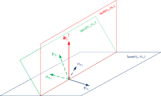
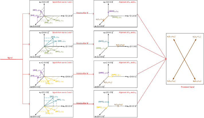
By jointly designing the precoding matrices at the source nodes and the processing matrix at the relay, our proposed GSA has successfully aligned the transmitted signals for each source node pair at the relay. The key steps of GSA are illustrated in Fig. 222 and Fig. 333. Fig. 2 shows that a1Tsuperscriptsubscripta1𝑇\textbf{a}_{1}^{T} falls into the null space of H2,rsubscriptH2𝑟\textbf{H}_{2,r} and H4,rsubscriptH4𝑟\textbf{H}_{4,r}. It is similar to other aisubscripta𝑖\textbf{a}_{i} (i=2, 3, 4) by (19) - (22). Fig. 3 shows the whole signal processing procedure to obtain the network-coded messages. Here, the signals received at relay after the effective channel AH is firstly given. Then the signals are rotated by V to be aligned in four orthogonal directions.

Refer to caption
Figure 2: The construction the processing matrix at relay.
Refer to caption
Figure 3: Generalized signal alignment procedure.

III-B BC Phase

During the BC phase, the relay broadcasts an estimate of the four network coded symbols using the precoding matrix 𝐔=[𝐮1,,𝐮4]𝐔subscript𝐮1subscript𝐮4{\bf U}=[{\bf u}_{1},...,{\bf u}_{4}]. More specifically, 𝐮1,𝐮2,𝐮𝟑,𝐮𝟒subscript𝐮1subscript𝐮2subscript𝐮3subscript𝐮4{\bf u}_{1},~{}{\bf u}_{2},~{}{\bf u_{3}},~{}{\bf u_{4}} are for symbols s13+s31,s14+s41,s23+s32,s24+s42subscript𝑠13subscript𝑠31subscript𝑠14subscript𝑠41subscript𝑠23subscript𝑠32subscript𝑠24subscript𝑠42s_{13}+s_{31},s_{14}+s_{41},s_{23}+s_{32},s_{24}+s_{42}, respectively. Each beamformer is designed as below

u1Null[Gr,2Gr,4],u2Null[Gr,2Gr,3]formulae-sequencesubscriptu1Nulldelimited-[]subscriptG𝑟2missing-subexpressionmissing-subexpressionsubscriptG𝑟4missing-subexpressionmissing-subexpressionsubscriptu2Nulldelimited-[]subscriptG𝑟2missing-subexpressionmissing-subexpressionsubscriptG𝑟3missing-subexpressionmissing-subexpression\textbf{u}_{1}\subseteq\textbf{Null}\left[\begin{array}[]{ccc}\textbf{G}_{r,2}\\ \textbf{G}_{r,4}\end{array}\right],~{}\textbf{u}_{2}\subseteq\textbf{Null}\left[\begin{array}[]{ccc}\textbf{G}_{r,2}\\ \textbf{G}_{r,3}\end{array}\right]
u3Null[Gr,1Gr,4],u4Null[Gr,1Gr,3].formulae-sequencesubscriptu3Nulldelimited-[]subscriptG𝑟1missing-subexpressionmissing-subexpressionsubscriptG𝑟4missing-subexpressionmissing-subexpressionsubscriptu4Nulldelimited-[]subscriptG𝑟1missing-subexpressionmissing-subexpressionsubscriptG𝑟3missing-subexpressionmissing-subexpression\textbf{u}_{3}\subseteq\textbf{Null}\left[\begin{array}[]{ccc}\textbf{G}_{r,1}\\ \textbf{G}_{r,4}\end{array}\right],~{}\textbf{u}_{4}\subseteq\textbf{Null}\left[\begin{array}[]{ccc}\textbf{G}_{r,1}\\ \textbf{G}_{r,3}\end{array}\right]. (26)

Since [Gr,jT,Gr,kT]TsuperscriptsuperscriptsubscriptG𝑟𝑗𝑇superscriptsubscriptG𝑟𝑘𝑇𝑇\left[\textbf{G}_{r,j}^{T},~{}\textbf{G}_{r,k}^{T}\right]^{T} is a 4×5454\times 5 matrix, we can always find these beamforming vectors to satisfy the above conditions.

Plugging (26) into (5), we can obtain the received signal for source node 111 as below

𝐲1=𝐆r,1𝐔𝐬^+𝐧1subscript𝐲1subscript𝐆𝑟1𝐔subscript^𝐬direct-sumsubscript𝐧1\displaystyle{\bf y}_{1}={\bf G}_{r,1}{\bf U}\hat{{\bf s}}_{\oplus}+{\bf n}_{1}~{}~{}~{}~{}~{}~{}~{}~{}~{}~{}~{}~{}~{}~{}~{}~{}~{}~{}~{}~{}~{}~{}~{}~{}~{}~{}~{}~{}~{}~{}~{}~{}~{}~{}~{}
=𝐆r,1[𝐮1(s13+s31)+𝐮2(s14+s41)]+𝐧1.absentsubscript𝐆𝑟1delimited-[]subscript𝐮1subscript𝑠13subscript𝑠31subscript𝐮2subscript𝑠14subscript𝑠41subscript𝐧1\displaystyle={\bf G}_{r,1}\big{[}{\bf u}_{1}(s_{13}+s_{31})+{\bf u}_{2}(s_{14}+s_{41})\big{]}+{\bf n}_{1}. (27)

Since source node 111 knows s13subscript𝑠13s_{13} and s14subscript𝑠14s_{14}, it can decode the desired signal from (27) after applying self-interference cancellation. In the same manner, the other source nodes can also obtain the signals intended for themselves. Thus, the total DoF of 888 is achieved, which is also the upper bound for the network when M=2,N=5formulae-sequence𝑀2𝑁5M=2,N=5.

III-C Extension to M=2𝑀2M=2, N>5𝑁5N>5

When M=2,N>5formulae-sequence𝑀2𝑁5M=2,N>5, we can always find the null space for aisubscripta𝑖\textbf{a}_{i} (i=1,2,3,4) by (19)-(22). The precoding matrix V then can be calculated by (25). It can be seen that uisubscriptu𝑖\textbf{u}_{i} exists by (26). Thus, we can apply our proposed GSA-based transmission scheme for MIMO two-way X relay channel to achieve the total DoF of 888. We omit the proof here.

IV Achievability of The Upper Bound

In this section, we will generalize the method in the previous section to arbitrary N𝑁N, M𝑀M with M<N2𝑀𝑁2M<\frac{N}{2} and we will show that it can achieve the DoF upper bound 4M4𝑀4M when M2N5𝑀2𝑁5M\leq\lfloor\frac{2N}{5}\rfloor for even M𝑀M, and M2N15𝑀2𝑁15M\leq\lfloor\frac{2N-1}{5}\rfloor for odd M𝑀M.

We first consider the case when M𝑀M is even. The proposed GSA-based transmission scheme achieves total DoF upper bound d13=d14=d23=d24=d31=d32=d41=d42=M2subscript𝑑13subscript𝑑14subscript𝑑23subscript𝑑24subscript𝑑31subscript𝑑32subscript𝑑41subscript𝑑42𝑀2d_{13}=d_{14}=d_{23}=d_{24}=d_{31}=d_{32}=d_{41}=d_{42}=\frac{M}{2}, yielding a total DoF of 4M4𝑀4M. Denote s=[s131+s311,s132+s312,,s13M2+s31M2,s141+s411,,s14M2+s41M2,s231+s321,,s23M2+s32M2,s241+s421,,s24M2+s42M2]Tsubscriptsdirect-sumsuperscriptsuperscriptsubscript𝑠131superscriptsubscript𝑠311superscriptsubscript𝑠132superscriptsubscript𝑠312superscriptsubscript𝑠13𝑀2superscriptsubscript𝑠31𝑀2superscriptsubscript𝑠141superscriptsubscript𝑠411superscriptsubscript𝑠14𝑀2superscriptsubscript𝑠41𝑀2superscriptsubscript𝑠231superscriptsubscript𝑠321superscriptsubscript𝑠23𝑀2superscriptsubscript𝑠32𝑀2superscriptsubscript𝑠241superscriptsubscript𝑠421superscriptsubscript𝑠24𝑀2superscriptsubscript𝑠42𝑀2𝑇\textbf{s}_{\oplus}=[s_{13}^{1}+s_{31}^{1},s_{13}^{2}+s_{31}^{2},\cdots,s_{13}^{\frac{M}{2}}+s_{31}^{\frac{M}{2}},s_{14}^{1}+s_{41}^{1},\cdots,s_{14}^{\frac{M}{2}}+s_{41}^{\frac{M}{2}},s_{23}^{1}+s_{32}^{1},\cdots,s_{23}^{\frac{M}{2}}+s_{32}^{\frac{M}{2}},s_{24}^{1}+s_{42}^{1},\cdots,s_{24}^{\frac{M}{2}}+s_{42}^{\frac{M}{2}}]^{T} as the network-coded messages expected to obtain at the relay, where sijksuperscriptsubscript𝑠𝑖𝑗𝑘s_{ij}^{k} denotes the k𝑘k-th data streams from source node i𝑖i to source node j𝑗j.

Denoting AisubscriptA𝑖\textbf{A}_{i} as the ((i1)M2+1)𝑖1𝑀21(\frac{(i-1)M}{2}+1)-th to the (iM2)𝑖𝑀2(\frac{iM}{2})-th row vectors of A, for i=1,,4𝑖14i=1,\cdots,4. Each 𝐀isubscript𝐀𝑖{\bf A}_{i} can be thought as a combining matrix for the transmitted signals of a source node pair. Thus, we design AisubscriptA𝑖\textbf{A}_{i} similar to (19) and (22) as the following:

𝐀1TNull[𝐇2,r𝐇4,r]Tsuperscriptsubscript𝐀1𝑇Nullsuperscriptdelimited-[]subscript𝐇2𝑟subscript𝐇4𝑟𝑇\displaystyle{\bf A}_{1}^{T}\subseteq\textbf{Null}~{}\big{[}{\bf H}_{2,r}~{}{\bf H}_{4,r}\big{]}^{T}~{}
𝐀2TNull[𝐇2,r𝐇3,r]Tsuperscriptsubscript𝐀2𝑇Nullsuperscriptdelimited-[]subscript𝐇2𝑟subscript𝐇3𝑟𝑇\displaystyle{\bf A}_{2}^{T}\subseteq\textbf{Null}~{}\big{[}{\bf H}_{2,r}~{}{\bf H}_{3,r}\big{]}^{T}~{}
𝐀3TNull[𝐇1,r𝐇4,r]Tsuperscriptsubscript𝐀3𝑇Nullsuperscriptdelimited-[]subscript𝐇1𝑟subscript𝐇4𝑟𝑇\displaystyle{\bf A}_{3}^{T}\subseteq\textbf{Null}~{}\big{[}{\bf H}_{1,r}~{}{\bf H}_{4,r}\big{]}^{T}~{}
𝐀4TNull[𝐇1,r𝐇3,r]T.superscriptsubscript𝐀4𝑇Nullsuperscriptdelimited-[]subscript𝐇1𝑟subscript𝐇3𝑟𝑇\displaystyle{\bf A}_{4}^{T}\subseteq\textbf{Null}~{}\big{[}{\bf H}_{1,r}~{}{\bf H}_{3,r}\big{]}^{T}. (28)

Here, A1subscriptA1\textbf{A}_{1} is for source pair (1,3), A2subscriptA2\textbf{A}_{2} is for source pair (1,4), A3subscriptA3\textbf{A}_{3} is for source pair (2,3) and A4subscriptA4\textbf{A}_{4} is for source pair (2,4).

We can see that AiTsuperscriptsubscriptA𝑖𝑇\textbf{A}_{i}^{T} is an N×M2𝑁𝑀2N\times\frac{M}{2} matrix and [Hj,rHk,r]Tsuperscriptdelimited-[]subscriptH𝑗𝑟subscriptH𝑘𝑟𝑇\left[\textbf{H}_{j,r}~{}\textbf{H}_{k,r}\right]^{T} is a 2M×N2𝑀𝑁2M\times N matrix. The matrix AiTsuperscriptsubscriptA𝑖𝑇\textbf{A}_{i}^{T} exists if and only if N2MM2𝑁2𝑀𝑀2N-2M\geq\frac{M}{2}, which is equivalent to M2N5𝑀2𝑁5M\leq\lfloor\frac{2N}{5}\rfloor.

After obtaining the matrix A, we can get the matrix V using the same method as (25) in Section III. Then we show the existence of the precoding matrix U (N×2M𝑁2𝑀N\times 2M). We can write U as

U=[U1U2U3U4],Udelimited-[]subscriptU1subscriptU2subscriptU3subscriptU4missing-subexpressionmissing-subexpression\textbf{U}=\left[\begin{array}[]{ccc}\textbf{U}_{1}~{}\textbf{U}_{2}~{}\textbf{U}_{3}~{}\textbf{U}_{4}\end{array}\right], (29)

where each UisubscriptU𝑖\textbf{U}_{i} is an N×M2𝑁𝑀2N\times\frac{M}{2} matrix and

U1Null[Gr,2Gr,4],U2Null[Gr,2Gr,3]formulae-sequencesubscriptU1Nulldelimited-[]subscriptG𝑟2missing-subexpressionmissing-subexpressionsubscriptG𝑟4missing-subexpressionmissing-subexpressionsubscriptU2Nulldelimited-[]subscriptG𝑟2missing-subexpressionmissing-subexpressionsubscriptG𝑟3missing-subexpressionmissing-subexpression\textbf{U}_{1}\subseteq\textbf{Null}\left[\begin{array}[]{ccc}\textbf{G}_{r,2}\\ \textbf{G}_{r,4}\end{array}\right],~{}\textbf{U}_{2}\subseteq\textbf{Null}\left[\begin{array}[]{ccc}\textbf{G}_{r,2}\\ \textbf{G}_{r,3}\end{array}\right]
U3Null[Gr,1Gr,4],U4Null[Gr,1Gr,3].formulae-sequencesubscriptU3Nulldelimited-[]subscriptG𝑟1missing-subexpressionmissing-subexpressionsubscriptG𝑟4missing-subexpressionmissing-subexpressionsubscriptU4Nulldelimited-[]subscriptG𝑟1missing-subexpressionmissing-subexpressionsubscriptG𝑟3missing-subexpressionmissing-subexpression\textbf{U}_{3}\subseteq\textbf{Null}\left[\begin{array}[]{ccc}\textbf{G}_{r,1}\\ \textbf{G}_{r,4}\end{array}\right],~{}\textbf{U}_{4}\subseteq\textbf{Null}\left[\begin{array}[]{ccc}\textbf{G}_{r,1}\\ \textbf{G}_{r,3}\end{array}\right]. (30)

We can see that [Gr,jGr,k]Tsuperscriptdelimited-[]subscriptG𝑟𝑗subscriptG𝑟𝑘𝑇\left[\textbf{G}_{r,j}~{}~{}\textbf{G}_{r,k}\right]^{T} is a 2M×N2𝑀𝑁2M\times N matrix. The matrix UisubscriptU𝑖\textbf{U}_{i} exists if and only if N2MM2𝑁2𝑀𝑀2N-2M\geq\frac{M}{2}, which is equivalent to M2N5𝑀2𝑁5M\leq\lfloor\frac{2N}{5}\rfloor. Hence, we can apply GSA-based transmission scheme when M𝑀M is even and M2N5𝑀2𝑁5M\leq\lfloor\frac{2N}{5}\rfloor.

Similarly, we can achieve the upper bound of the DoF 4M4𝑀4M by d13=d24=d31=d42=M+12subscript𝑑13subscript𝑑24subscript𝑑31subscript𝑑42𝑀12d_{13}=d_{24}=d_{31}=d_{42}=\frac{M+1}{2} and d14=d23=d32=d41=M12subscript𝑑14subscript𝑑23subscript𝑑32subscript𝑑41𝑀12d_{14}=d_{23}=d_{32}=d_{41}=\frac{M-1}{2} when M𝑀M is odd. The corresponding matrices A and U exist if and only if N2MM+12𝑁2𝑀𝑀12N-2M\geq\frac{M+1}{2}, which is equivalent to M2N15𝑀2𝑁15M\leq\lfloor\frac{2N-1}{5}\rfloor.

Note that the proposed GSA based transmission scheme can be applied to align signal pairs even when N>2M𝑁2𝑀N>2M. In this case, A is an identity matrix, and GSA reduces to the conventional SA.

Finally, we summarize the generalized signal alignment procedure in the following chart.

   Outline of Generalized Signal Alignment  

  • Step 1.  construct the matrix H using the channel matrices H1,rsubscriptH1𝑟\textbf{H}_{1,r}, H2,rsubscriptH2𝑟\textbf{H}_{2,r}, H3,rsubscriptH3𝑟\textbf{H}_{3,r}, H4,rsubscriptH4𝑟\textbf{H}_{4,r} according to (15).

  • Step 2.  Design the relay processing matrix A according to (IV).

  • Step 3. Compute the effective channel in the MAC phase AH and construct the source precoding matrix V according to (25).

  • Step 4.  Design the BC precoding matrix U with matrix Gr,1subscriptG𝑟1\textbf{G}_{r,1}, Gr,2subscriptG𝑟2\textbf{G}_{r,2}, Gr,3subscriptG𝑟3\textbf{G}_{r,3}, Gr,4subscriptG𝑟4\textbf{G}_{r,4} according to (30).


V Numerical Results

In this section, we provide numerical results to show the sum rate performance of the proposed scheme for the MIMO two-way X relay channel. The channel between each source node and the relay node is modeled as Rayleigh distribution with unit variance and it is independent for different node. The numerical results are illustrated with the ratio of the total transmitted signal power to the noise variance at each receive antenna and the total throughput of the channel. Each result is averaged over 10000 independent channel realizations.

We now explain how we compute the sum rate for the MIMO two-way X relay channel when applying the GSA transmission scheme.

GSA transmission scheme can be used in both amplify-and-forward (AF) and decode-and-forward (DF) strategy. From (15) and (27), when we apply AF strategy, we can obtain

yi=Gr,iU(s+Anr)+ni.subscripty𝑖subscriptG𝑟𝑖Usubscriptsdirect-sumsubscriptAn𝑟subscriptn𝑖\textbf{y}_{i}=\textbf{G}_{r,i}\textbf{U}(\textbf{s}_{\oplus}+\textbf{A}\textbf{n}_{r})+\textbf{n}_{i}. (31)

Let Risubscript𝑅𝑖R_{i} denote the sum rate of the source node i𝑖i. We calculate R1subscript𝑅1R_{1} as a representative. First, we write the received signal of source node 1 with AF strategy as

𝐲1=𝐆r,1𝐔s+𝐆r,1𝐔𝐀𝐧r+𝐧1subscript𝐲1subscript𝐆𝑟1𝐔subscriptsdirect-sumsubscript𝐆𝑟1subscript𝐔𝐀𝐧𝑟subscript𝐧1{\bf y}_{1}={\bf G}_{r,1}{\bf U}\textbf{s}_{\oplus}+{\bf G}_{r,1}{\bf U}{\bf A}{\bf n}_{r}+{\bf n}_{1}~{}~{}~{}~{}~{}~{}~{}~{}~{}~{}~{}~{}~{}~{}~{}~{}~{}~{}~{}~{}~{}~{}~{}~{}~{}~{}~{}~{}~{}~{}~{}~{}~{}~{}
=𝐆r,1[𝐔1(s13+s31)+𝐔2(s14+s41)]Signal+𝐆r,1UA𝐧r+𝐧1Noiseabsentsubscriptsubscript𝐆𝑟1delimited-[]subscript𝐔1subscripts13subscripts31subscript𝐔2subscripts14subscripts41𝑆𝑖𝑔𝑛𝑎𝑙subscriptsubscript𝐆𝑟1UAsubscript𝐧𝑟subscript𝐧1𝑁𝑜𝑖𝑠𝑒~{}~{}~{}=\underbrace{{\bf G}_{r,1}\big{[}{\bf U}_{1}(\textbf{s}_{13}+\textbf{s}_{31})+{\bf U}_{2}(\textbf{s}_{14}+\textbf{s}_{41})\big{]}}_{Signal}+\underbrace{{\bf G}_{r,1}{\textbf{U}}{\textbf{A}}{\bf n}_{r}+{\bf n}_{1}}_{Noise}
=G~r,1s~1+n~1.absentsubscript~G𝑟1subscript~s1subscript~n1=\tilde{\textbf{G}}_{r,1}\tilde{\textbf{s}}_{1}+\tilde{\textbf{n}}_{1}.~{}~{}~{}~{}~{}~{}~{}~{}~{}~{}~{}~{}~{}~{}~{}~{}~{}~{}~{}~{}~{}~{}~{}~{}~{}~{}~{}~{}~{}~{}~{}~{}~{}~{}~{}~{}~{}~{}~{}~{}~{}~{}~{}~{}~{} (32)

Then we can calculate the sum rate R1subscript𝑅1R_{1} in bits per channel use from source node 3 and source node 4 to source node 1 by (V)

R1=log2[det(𝐈+(ε(n~1n~1H))1G~r,1ε[s~1s~1H]G~r,1H)]subscript𝑅1subscript2𝐈superscript𝜀subscript~n1superscriptsubscript~n1𝐻1subscript~G𝑟1𝜀delimited-[]subscript~s1superscriptsubscript~s1𝐻superscriptsubscript~G𝑟1𝐻R_{1}=\log_{2}[\det({\bf I}+(\varepsilon(\tilde{\textbf{n}}_{1}\tilde{\textbf{n}}_{1}^{H}))^{-1}\tilde{\textbf{G}}_{r,1}\varepsilon[\tilde{\textbf{s}}_{1}\tilde{\textbf{s}}_{1}^{H}]\tilde{\textbf{G}}_{r,1}^{H})] (33)

Similarly, we can calculate R2subscript𝑅2R_{2}, R3subscript𝑅3R_{3}, R4subscript𝑅4R_{4} with the same method. Then total sum rate is given by

R=i=14Ri.𝑅superscriptsubscript𝑖14subscript𝑅𝑖R=\sum_{i=1}^{4}{R_{i}}. (34)

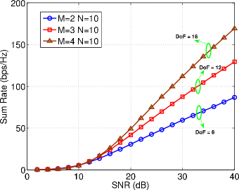
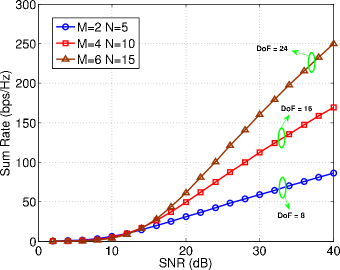
In Fig. 4, we plot the sum rate performance of the proposed generalized signal alignment transmission scheme at fixed N𝑁N but varying M𝑀M (M<N/2𝑀𝑁2M<N/2). In the figure, SNR denotes the total transmitted signal power from all the four source nodes to the noise variance at relay. We can observe that the increasing speed of sum-rate (the increase in bps/Hz for every 3dB in SNR) matches with the theoretical DoF 4M4𝑀4M very well when SNR is high enough.

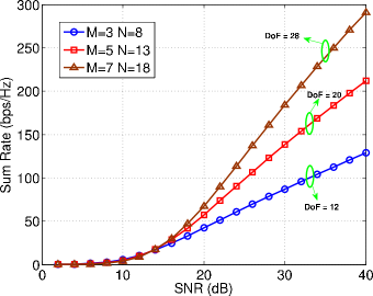
In Fig. 5 and Fig. 6, we plot the sum rate performance of the proposed GSA transmission scheme at the antenna configurations of M=2N5𝑀2𝑁5M=\lfloor\frac{2N}{5}\rfloor for even M𝑀M and M=2N15𝑀2𝑁15M=\lfloor\frac{2N-1}{5}\rfloor for odd M𝑀M, respectively. The upper bound of the DoF of 4M4𝑀4M is also achieved. These results indicate that our proposed GSA transmission scheme is feasible and effective.

Refer to caption
Figure 4: Total DoF for the MIMO two-way X relay channel under generalized signal alignment transmission scheme.
Refer to caption
Figure 5: Total DoF for the MIMO two-way X relay channel when M=2N5𝑀2𝑁5M=\frac{2N}{5}.
Refer to caption
Figure 6: Total DoF for the MIMO two-way X relay channel when M=2N15𝑀2𝑁15M=\frac{2N-1}{5}.

VI Conclusion

In this paper, we have analyzed the achievability of the DoF upper bound for the MIMO two-way X relay channal when MN2𝑀𝑁2M\leq\frac{N}{2}. In the newly-proposed GSA transmission scheme, the processing matrix at the relay and the precoding matrix at the source nodes are designed jointly so that the signals to be exchanged between each source node pair are aligned at the relay. We showed that when M2N5𝑀2𝑁5M\leq\lfloor\frac{2N}{5}\rfloor(M𝑀M is even) or M2N15𝑀2𝑁15M\leq\lfloor\frac{2N-1}{5}\rfloor(M𝑀M is odd), the upper bound of the total DoF 4M4𝑀4M is achieved. Theoretical analysis and numerical results both show that the transmission scheme proposed is feasible and effective.

References

  • [1] B. Rankov and A.Wittneben, “Spectral efficient protocols for half-duplex fading relay channels,” IEEE Journal on Selected Areas in Communications, vol. 25, no. 2, Feb. 2007.
  • [2] S. Zhang, S. Liew, and P. Lam, “Physical layer network coding,” in Proc. ACM MobiCom, Sep. 2006, pp. 63–68.
  • [3] S. Katti, S. Gollakota, and D. Katabi, “Embracing wireless interference: Analog network coding,” in Proc. ACM SIGCOMM, Sep. 2007, pp. 397–408.
  • [4] R. R. Vaze and R. W. Heath, “Capacity scaling for MIMO two-way relaying,” in IEEE International Symposium on Information Theory, Jun. 2007, pp. 1451 – 1455.
  • [5] S. Jafar and S. Shamai, “Degrees of freedom region of the MIMO X channel,” IEEE Transactions on Information Theory, vol. 54, no. 1, pp. 151–170, Jan. 2008.
  • [6] M. Maddah-Ali, A. Motahari, and A. Khandani, “Communication over MIMO X channels: Interference alignment, decomposition, and performance analysis,” IEEE Transactions on Information Theory, vol. 54, no. 8, pp. 3457–3470, Aug. 2008.
  • [7] N. Lee and J.-B. Lim, “A novel signaling for communication on MIMO Y channel: Signal space alignment for network coding,” IEEE International Symposium on Information Theory, pp. 2892 – 2896, 2009.
  • [8] N. Lee, J. Lee, and J. Chun, “Degrees of freedom on the MIMO Y channel: signal space alignment for network coding,” IEEE Transactions on Information Theory, vol. 56, no. 7, pp. 3332 – 3342, Jul. 2010.
  • [9] K. Lee, N. Lee, and I. Lee, “Achievable degrees of freedom on K-user Y channels,” IEEE Transactions on Wireless Communications, vol. 11, no. 3, pp. 1210 – 1219, Mar. 2012.
  • [10] Z. Xiang, M. Tao, J. Mo, and X. Wang, “Degrees of freedom for MIMO two-way X relay channel,” IEEE Transactions on Signal Processing, vol. 61, pp. 1711 – 1720, 2013.