Critical role of substrate in the high temperature superconductivity of single layer FeSe on Nb:BaTiO3
In the quest for high temperature superconductors, the interface between a metal and a dielectric was proposed to possibly achieve very high superconducting transition temperature () through interface-assisted pairing Little ; Ginzburg . Recently, in single layer FeSe (SLF) films grown on SrTiO3 substrates, signs for up to 65 K have been reported FeSeZhou2 ; TanFeSe . However, besides doping electrons and imposing strain, whether and how the substrate facilitates the superconductivity are still unclear. Here we report the growth of various SLF films on thick BaTiO3 films atop KTaO3 substrates, with signs for up to K, close to the liquid nitrogen boiling temperature. SLF of similar doping and lattice is found to exhibit high only if it is on the substrate, and its band structure strongly depends on the substrate. Our results highlight the profound role of substrate on the high- in SLF, and provide new clues for understanding its mechanism.
The record has long been 56 K for the bulk iron-based high temperature superconductors (Fe-HTS’s). Recently, in SLF films grown on Nb doped SrTiO3 (NSTO) substrate (hereafter referred as FeSeS) by molecular beam epitaxy (MBE), both scanning tunneling spectroscopy and angle-resolved photoemission spectroscopy (ARPES) experiments have observed large superconducting gap FeSeXue ; FeSeZhou , which closes at 65 K (ref. FeSeZhou2, ; TanFeSe, ). On the other hand, ex situ transport measurements of SLF films capped with FeTe and silicon show an onset of about 40 K, with signs for a possible Berezinskii-Kosterlitz-Thouless (BKT) transition WangjianFeSe . Although whether this is the true remains to be checked by in-situ transport measurements, it is likely that the phase fluctuation in this two dimensional system is strong, so that the ARPES gap-closing temperature, , only measures the Cooper pair formation temperature, instead of . Nevertheless, it implies that a equivalent to can be achieved if the fluctuations in such a two dimensional system could be suppressed.
Based on the existing experiments, the NSTO substrate affects SLF in the following ways. 1. The oxygen vacancies in the substrate induces extra electrons that are transferred to the interfacial FeSe layer TanFeSe ; ZhangSBcalc , which suppresses the antiferromagnetism in SLF and allows for a high (ref. TanFeSe, ). 2. The in-plane lattice constant () of NSTO is 3.905 Å , thus it imposes a large tensile strain on SLF, noting =3.765 Å for bulk FeSe. It was shown that the tensile strain would enhance the antiferromagnetic interactions in FeSe (ref. CaoFeSe, ). However, for SLF films with extremely expanded of 3.99 Å in epitaxially grown FeSe/NSTO/KTaO3 heterostructures (hereafter referred as FeSeSX), the increases just moderately to about 70 K (ref. PengSTOKTO, ). 3. It was reported recently that electrons in FeSe might interact with an meV optical phonon in the substrate ZXShenFeSe . So far, it is still unclear whether and how the substrate plays a more direct role in mediating the superconducting pairing in SLF.
To study the role of substrate in SLF superconductivity, different substrates should be examined. BaTiO3 (BTO) can be made with the same TiO2 termination as STO. However, due to the spontaneous polarization of BTO, atomically flat surface is hard to obtain with bulk BTO. To overcome this, since BTO lattice (=3.992 Å) is merely 0.075 % larger than that of KTaO3 (KTO), we first grew 40 u.c. of Nb-doped BTO (NBTO, to provide a conducting substrate) on the (001) surface of a KTO crystal by ozone assisted MBE, then grew SLF on the NBTO film (Fig. 1a) as described in the Methods section. This heterostructure, hereafter referred as FeSeB, is then transferred to the analysis chamber under ultra high vacuum for the in-situ measurements of low energy electron diffraction (LEED) and ARPES.
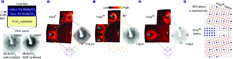
The as-grown well-oxidized NBTO film exhibits a nice surface with the symmetry of the substrate, as shown by its LEED pattern in Fig. 1a. However, after heat treated at 950∘C under the selenium flux, the NBTO film exhibits a 33 reconstruction. This has an direct impact on the SLF grown on it. The left part of Fig. 1b shows the photoemission intensity map at the Fermi energy () for FeSeB, where three sets of Fermi surfaces are observed. One set (unrotated) is made of elliptical Fermi surface sheets, similar to that observed in FeSeSX (ref. PengSTOKTO, ). The other two sets are made of more circular sheets, similar to the Fermi surface topology of FeSeS film. Although these Fermi surface sheets appear to cross each other, their band structures do not exhibit any hybridization. This indicate that they are likely originated from three types of spatially separated domains. Moreover, the superstructure in the substrate does not cause any observable folding, indicating that the crystal potential of the substrate affect the FeSe rather weakly OuHongweiPRL . The in-plane lattice constant of each domain could be derived from the inversed Brillouin zone size determined by high symmetry points of photoemission map TanFeSe . We found that one domain preserves the lattice of the KTO substrate (3.99 Å ), and the other two domains rotated about with 3.78 Å . Consistently, the LEED pattern of FeSeB in Fig. 1b can be decomposed into three sets of spots. Besides the main spots that reflect the unrotated lattice of the substrate (highlighted by the blue square), there are spots corresponding to two rotated lattices (highlighted by the two yellow squares). As shown in Fig. 1e, these three domains of FeSe match the reconstructed substrate. Particularly, every 10 periods of the rotated FeSe lattice match the diagonal of a 39 rectangle of the NBTO lattice (the dashed line in Fig. 1e).
After post-annealing for over 15 hours (details are shown in the Supplementary Information), the domains with the relaxed lattice could be further enhanced (such a film is referred as FeSeBR hereafter). As shown in Fig. 1c, the spots correspond to the rotated lattices become stronger, while those correspond to the unrelaxed lattice is weakened. As expected, the elliptical Fermi surfaces sheets is neligibly weak. Intriguingly, we found that if some extra BaO is inserted during the growth of NBTO film, as shown in Fig. 1a, the resulting FeSe film only contains single unrelaxed domain, as illustrated by its LEED pattern in Fig. 1d. Such an unrelaxed film is referred as FeSeBU hereafter. Consistently, the Fermi surface topology only contains orthogonal ellipses. Based on the calculated Luttinger volume, there are 0.12 excessive electrons per Fe for all these films, similar to those SLF on NSTO as well.
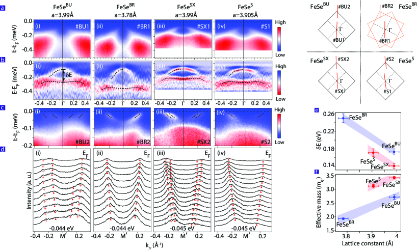
Fig. 2 presents the band dispersions for various SLF films grown on NBTO or NSTO. Fig. 2a,b gives the dispersions across (0,0). The generic features for all films include a parabolic band, and a relative flat band at higher binding energy. For films grown on NBTO, the larger correspond to a larger band mass of the parabolic band and smaller separations between the two bands (Fig. 2b(i),(ii)), indicating stronger correlation effects with expanded lattice. The same holds true for the two films grown on NSTO (Fig. 2b(iii),(iv)). Intriguingly, even though both the NBTO/KTO and NSTO/KTO were terminated with the same TiO2 layers that have the similar amount of oxygen vacancies and same lattice constant of 3.989 Å , there are clear differences in the band dispersions for FeSeSX and FeSeBU (Fig. 2b(i),(iii)). The bands are flatter for SLF on NSTO than for SLF on NBTO. As summarized in Fig. 2f,g, the two characteristic quantities (band mass and band separation) fall on two separate curves as a function of , which clearly indicates the substrates have a nontrivial effects on the correlation and electronic structure in the FeSe film on them. The substrates affect the bands around M as well (Fig. 2c,d). For the large =3.989 Å , two electron bands are resolved for FeSeBU and FeSeSX but with different separations (Fig. 2d(i),(iii)) PengSTOKTO , while for FeSeBR and FeSeS, the two bands cannot be resolved TanFeSe . However, the bandwidths of the electron bands are similar in all these films.
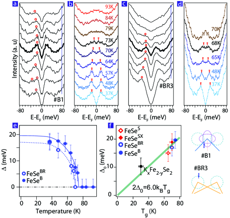
The superconducting properties of the FeSe films grown on the NBTO films are examined in Fig. 3. Fig. 3a shows the symmetrized energy distribution curves (EDC’s) at low temperatures along a cut across the Fermi surface of the unrelaxed FeSe domains of FeSeB. The dispersion exhibits a characteristic bending back behavior after passing the Fermi momentum. This is a hallmark of Bogliubov quasiparticle dispersion, and indicates that the gap is due to Cooper pair formation. The symmetrized EDC’s at the normal state Fermi momenta could be used to identify the gap by the spectral weight suppression at , which is minimally affected by the temperature broadening effects Norman . Fig. 3b presents the temperature dependence of the symmetrized EDC’s at the Fermi momentum for the unrelaxed domains in FeSeB, and the gap decreases with increasing temperature and eventually closes above 73 K. Fig. 3c-d shows the gap behavior of FeSeBR, which closes above 68 K. The data for FeSeBU shows rather weak coherence peaks, but with possible signs for above 77 K (see Supplementary Information).
The temperature dependence of the gap is shown in Fig. 3e, which could be well fitted by the Bardeen-Cooper-Schrieffer (BCS) gap vs. temperature formula. This, together with the Bogliubov quasiparticle behavior of the dispersion, suggest that it relates to the Cooper pair formation, although in-situ transport is needed to check if . The fitted is 752 K, and 702 K for FeSeB and FeSeBR, respectively. The former sets a new record for Fe-HTS’s. Fig. 3f summarize the maximal gap versus for FeSe films and KxFe2-ySe2. One can find a general linear trend between and the gap amplitude, reflecting their superconducting nature. However, we note that the ’s of the FeSeBR and FeSeBU domains differ by 5.5%. When the lattice is expanded by such a large amount, the antiferromagnetic superexchange interactions across the Fe-Se-Fe would enhance significantly CaoFeSe . In the context of the antiferromagnetic-interaction/spin fluctuation mediated superconductivity, which is arguably the current dominating picture for bulk Fe-HTS’s HuDing , such a 5 K difference is surprisingly small. In addition, there is no simple relation between the effective mass and , while the increased correlation strength usually should help to enhance the superconductivity in such a high doping regime.
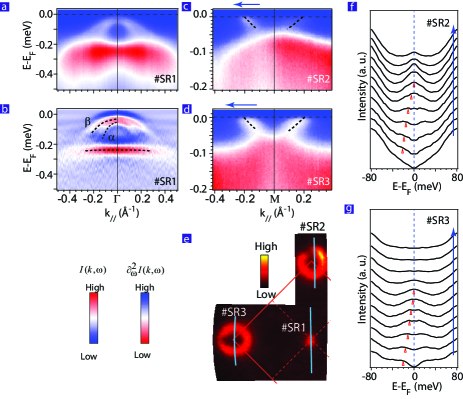
The of FeSeBR is close to that of bulk FeSe. It has been shown both by experiments and calculations that the undoped bulk FeSe has similar electronic structure as the iron pnictides with both electron and hole Fermi pockets LuFeSeCalc ; TanFeSe . For iron pnictides, heavy electron doping would fill up the hole pockets, bring the system to the overdoped regime, and kill the superconductivity Lifshitz1 ; Ye2013 . To check if this is the case for FeSe, we have grown 35 u.c. thick cobalt-doped FeSe film on NSTO to introduce electron carriers (named FeCoSeSR), and is relaxed to about 3.78 Å in this film. As shown in Fig. 4a,b, the hole pockets of the and bands sink below the Fermi energy, and the electron Fermi surface is fairly large as shown in Fig. 4c-e. About 8% electrons could be doped, which is limited by the solubility of cobalt. Fig. 4f,g shows no signs of a superconducting gap. The , if any, is below the lowest temperature of 30 K that could be reached at the film. That is, for a SLF film with similar and doping, it has a high of 70K on NBTO, while its is very low if such films are staked together in FeCoSeSR. Had the superconductivity been originated only from the FeSe layer, one would expect the opposite: a higer in FeCoSeSR due to suppressed fluctuations.
Our findings thus strongly suggest that interfacial effects could participate or even dominate the superconductivity in FeSe/NSTO or FeSe/NBTO. For example, one could speculate some intriguing and nonexclusive possibilities. For example, the polarizability of the ions in substrates induces interfacial electron-phonon interactions OuHongweiPRL . The interactions between electrons and a substrate-originated phonon have been reported in FeSeS (ref. ZXShenFeSe, ). The high phonon frequency and strong electron phonon interactions in NSTO or NBTO may mediate superconductivity with high as in BCS theory. It may also help enhance the antiferromagnetic-interaction mediated pairing as proposed in ref. DHLee, and ZXShenFeSe, . Moreover, Little Little and Ginzburg Ginzburg proposed almost half a century ago that the electronic polarizability of the substrate could introduce attractive force between electrons. This is unlikely here, since we did not find any noticeble dependence of the electronic structure and superconducting properties on the Nb concentration (i.e. conductivity and carrier density in the substrate). Nevertheless, it would help to screen the Coulomb interactions at various ranges Sawatzky , thus facilitate pairing Mona . In fact, the observed substrate-dependence of correlations in FeSe may be resulting from the different screening of the interactions by NSTO and NBTO.
To summarize, we have successfully fabricated FeSe films on NBTO films, and enhance the gap-closing or Cooper-pair formation temperature up to 75 K. This establishes interface engineering as an effective path for enhancing in SLF, and pave its way towards more cost-effective applications. More importantly, our data suggest that the substrate has a profound impact on the electronic structure in single layer FeSe/NSTO and FeSe/NBTO films, and their high temperature superconductivity probably results from an extraordinary interfacial mechanism. These results enrich the current understanding of interfacial superconductivity and high temperature superconductivity in general.
Methods:
Thin film growth
Over 40 unit cells of highly conductive 5% Nb doped BTO films were grown layer-by-layer on KTaO3 (KTO) substrate with ozone-assisted molecular beam epitaxy (MBE). During the growth of Nb:BTO, the reflection high-energy electron diffraction (RHEED) pattern retained its two dimensional character. With the shutter-controlled growth mode, the film is terminated with TiO2 layer after the growth of each unit cell except for FeSeBU (ref. RHEEDSchlom, ). The Nb:BTO films were then transferred under an ultra-high vacuum to another MBE chamber, where heat treatment were performed, and then FeSe thin films were deposited following the procedure used in ref. TanFeSe, . In this way, a FeSe/Nb:BTO/KTO heterostructure is fabricated.
ARPES measurement
ARPES data were taken in situ under ultra-high vacuum of , with a SPECS UVLS discharge lamp (21.2eV He-I light) and a Scienta R4000 electron analyzer. The energy resolution is 8 meV and the angular resolution is 0.3∘. Data were taken at 30 K if not specified otherwise. To eliminate the photoemission charging effect due to insulating KTO, silver paste was attached on the substrate edge before growth.
Acknowledgement: This work is supported in part by the National Science Foundation of China under the grant Nos. 91021001 and 91221303, and National Basic Research Program of China (973 Program) under the grant No. 2012CB921402.
Author contributions: R.P., H.C.X., S.Y.T., M.X., Q.S. and Z.C.Huang grew the films, R.P., H.C.X., S.Y.T., B.P.X., X.P.S., Z.C.Huang and C.H.P.Wen performed ARPES measurements. R. P., H.C.X., S.Y.T. and D.L.F. analyzed the ARPES data. D.L.F. and R.P. wrote the paper. D.L.F., B.P.X., and T.Z. are responsible for the infrastructure, project direction and planning.
Additional Information: The authors declare no competing financial interests. Correspondence and requests for materials should be addressed to D.L.F. (dlfeng@fudan.edu.cn).
References
- (1) Little, W. A. Possibility of synthesizing an organic superconductor. Phys. Rev. 134, A1416-A1424 (1964).
- (2) Ginzburg, V. L. On surface superconductivity. Physics Letters 13, 101-102 (1964).
- (3) He, S. L. et al. Phase diagram and high temperature superconductivity at 65K in tuning carrier concentration of single-layer FeSe films. Nature Mater. 12, 605-610 (2013).
- (4) Tan, S. Y. et al. Interface-induced superconductivity and strain-dependent spin density wave in FeSe/SrTiO3 thin films. Nature Mater. 12, 634-640 (2013).
- (5) Wang, Q. Y. et al. Interface induced high temperature superconductivity in single unit-cell FeSe films on SrTiO3. Chin. Phys. Lett. 29, 037402 (2012).
- (6) Liu, D.F. et al. Electronic origin of high-temperature superconductivity in single-layer FeSe superconductor. Nat. Commun. 3, 931 (2012).
- (7) Zhang, W. et al. Direct observation of high temperature superconductivity in one-unit-cell FeSe films, Chin. Phys. Lett. 31, 017401 (2014).
- (8) Bang, J. , et al. Atomic and electronic structures of single-layer FeSe on SrTiO3(001): The role of oxygen deficiency. Phys. Rev. B 87, 220503 (2013).
- (9) Cao. H. Y. , Tan, S. Y., Xiang, H. J., Feng, D. L. and Gong, X. G. The interfacial effects on the spin density wave in FeSe/SrTiO3 thin film. Preprint at http://arxiv.org/abs/1310.4024 (2013).
- (10) Peng, R. et al. Enhanced superconductivity and evidence for novel pairing in single-layer FeSe on SrTiO3 thin film under large tensile strain. Preprint at http://arxiv.org/abs/1310.3060 (2013).
- (11) Lee J. J., et al. Evidence for pairing enhancement in single unit cell FeSe on SrTiO3 due to cross-interfacial electron-phonon coupling. Preprint at http://arxiv.org/abs/1312.2633 (2013).
- (12) Ou, H. et al. Novel electronic structure induced by a highly strained oxide interface with incommensurate crystal fields. Phys. Rev. Lett. 102, 026806 (2009).
- (13) Norman, M. R., Randeria, M., Ding, H. & Campuzano, J. C. Phenomenology of the low-energy spectral function in high-Tc superconductors. Phys. Rev. B 57, R11093-R11096 (1998).
- (14) Zhang Y. et al. Nodeless superconducting gap in AxFe2Se2 (A=K, Cs) revealed by angle-resolved photoemission spectroscopy. Nature Mater. 10, 273-277 (2011).
- (15) Hu, J. & Ding, H. Local antiferromagnetic exchange and collaborative Fermi surface as key ingredients of high temperature superconductors. Scientific Reports 2, 381 (2012).
- (16) Ma, F. et al. First-principles calculations of the electronic structure of tetragonal -FeTe and -FeSe crystals: Evidence for a bicollinear AFM order. Phys. Rev. Lett. 102, 177003 (2009).
- (17) Liu, C. et al. Importance of the Fermi-surface topology to the superconducting state of the electron-doped pnictide Ba(Fe1-xCox)2As2. Phys. Rev. B 84, 020509 (2011).
- (18) Ye, Z. R. et al. Orbital selective correlations between nesting/scattering/Lifshitz transition and the superconductivity in AFe1-xCoxAs (A=Li, Na). Preprint at http://arxiv.org/abs/1303.0682 (2013).
- (19) Xiang, Y. Y., Wang, F., Wang. D., Wang Q. H. & Lee D. H. High-temperature superconductivity at the FeSe/SrTiO3 interface. Phys. Rev. B 86 134508 (2012).
- (20) Altieri, S., Tjengb, L.H. & Sawatzky G.A. Ultrathin oxide films on metals: new physics and new chemistry? Thin Solid Films 400, 9-15 (2001).
- (21) Berciu, M., Elfimov, I. & Sawatzky G.A. Electronic polarons and bipolarons in iron-based superconductors: The role of anions. Phys. Rev. B 79, 214507 (2009).
- (22) Haeni, J. H., Theis, C. D. & Schlom, D. G. RHEED intensity oscillations for the stoichiometric growth of SrTiO3 thin films by reactive molecular beam epitaxy. Journal of Electroceramics 4, 385-391 (2000).