chapter [1.5em] \contentslabel1em \titlerule*[1pc].\contentspage \titlecontentssection [3.5em] \contentslabel2.3em \titlerule*[1pc].\contentspage \titlecontentssubsection [4.5em] \contentslabel3em \titlerule*[1pc].\contentspage \titlecontentssubsubsection [5.5em] \contentslabel2.3em \titlerule*[1pc].\contentspage
Concept for an Electron Ion Collider (EIC) detector built around the BaBar solenoid
![[Uncaptioned image]](/html/1402.1209/assets/x1.png)
The PHENIX Collaboration
February 3, 2014
Executive Summary
The PHENIX collaboration presents here a concept for a detector at a future Electron Ion Collider (EIC). The exact performance specifications for an EIC in terms of energy and luminosity are being optimized. This document responds to a specific charge to evaluate the physics performance at an EIC at Brookhaven National Laboratory (BNL) with a potential turn-on date of 2025 is envisioned with an electron beam energy up to 10 GeV, hadron beam energies up to 255 GeV for protons and 100 GeV/nucleon for gold ions, and design luminosities of cm-2s-1 for 10 GeV on 255 GeV collisions. The EIC detector proposed here, referred to as ePHENIX, will have excellent performance for a broad range of exciting EIC physics measurements, providing powerful investigations not currently available that will dramatically advance our understanding of how quantum chromodynamics binds the proton and forms nuclear matter.Though not detailed in this study, this detector concept has increased physics reach and capabilities for significantly higher electron beam energies and luminosities with modest design augmentation.
In 2013, the PHENIX collaboration and Brookhaven National Laboratory submitted a proposal for an extensive update to the PHENIX detector. This upgrade, referred to as sPHENIX, consists of new large acceptance electromagnetic and hadronic calorimetry built around the superconducting solenoid recently acquired from the decommissioned BaBar experiment at SLAC. sPHENIX will make key new measurements of probes of the strongly coupled quark gluon plasma (sQGP) and allow for fundamental tests of our picture of its inner workings [1]. From the beginning, it was realized that the sPHENIX detector design, with its large bore superconducting solenoid, midrapidity calorimetry, open geometry, coupled with the existing investment in infrastructure in the PHENIX interaction region, provides an excellent foundation for an EIC detector. With this in mind, EIC design considerations for the sPHENIX proposal have been incorporated from the start [2].
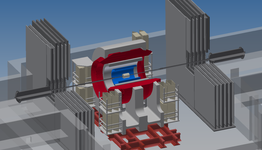
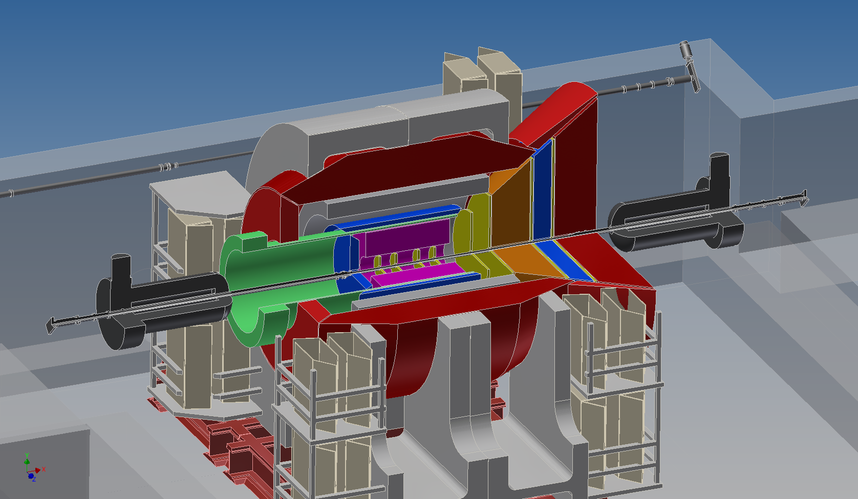
A full engineering rendering of the ePHENIX detector — showing how ePHENIX builds upon sPHENIX — is shown in Figure 1. In addition to fully utilizing the sPHENIX superconducting solenoid and barrel calorimetry, ePHENIX adds new detectors in the barrel and electron-going and hadron-going directions. In the electron-going direction a crystal calorimeter is added for electron identification and precision resolution. A compact time projection chamber, augmented by additional forward and backward angle GEM detectors, provides full tracking coverage. In the hadron-going direction, electromagnetic and hadronic calorimetry sits behind the tracking detectors. Critical particle identification capabilities are provided in the central rapidity region by a barrel DIRC and in the hadron-going direction by a gas RICH and an aerogel RICH. The sPHENIX upgrade could be ready for physics data taking in 2020 and the ePHENIX additions available for the earliest start of EIC physics in 2025.
The physics case for an EIC is documented in depth in the EIC White Paper [3]. An EIC with 5–10 GeV electron beam energies will enable major scientific advances in at least three main areas: 1) Detailed imaging of the spin and momentum structure of the nucleon; 2) Investigation of the onset of gluon saturation in heavy nuclei; and 3) Study of hadronization in cold nuclear matter. Again, for higher energies not detailed in this document, an augmented ePHENIX would extend this physics significantly including investigations of fundamental symmetries.
In this document we review each area with a focus on the connection to detector acceptance and performance requirements. We consider each subsystem in sufficient detail to be able to map out the performance using both parametrized and full Geant4 simulations. We find a broad suite of observables where ePHENIX has excellent capabilities.
The ePHENIX detector capably addresses much of the physics enabled at this EIC machine. We believe we have struck a strong balance between capabilities and costs for ePHENIX, but there remain clear targets for augmenting those capabilities—for instance, by adding a silicon vertex detector to enable measurements of open charm observables (e.g., ). In addition, there is a possibility to upgrade eRHIC to higher energy electron beams at a future date, and we believe ePHENIX provides an excellent base upon which an upgraded detector capable of exploiting the physics potential of those collisions could be built. There is also the potential, if one can realize appropriate instrumentation in the hadron-going direction while and A collisions are still available in RHIC, to pursue a rich program of forward physics measurements.
The PHENIX collaboration itself has outstanding detector expertise and technical support as a base for the construction of an EIC detector. Nonetheless, we view ePHENIX as a fundamentally new collaboration that would require and welcome the addition of new institutions bringing with them additional design and detector expertise, physics insights, and scientific leadership.
This document is organized as follows. Chapter 1 illustrates the wide spectrum of EIC physics that can be addressed. Chapter 2 describes the detector requirements that follow from that physics and which drive the ePHENIX design. Chapter 3 details the ePHENIX detector concept and shows its performance for key measurements.
Chapter 1 Physics at an Electron-Ion Collider
The 2007 Nuclear Physics Long Range Plan [4] states that the Electron-Ion Collider (EIC) embodies “the vision for reaching the next QCD frontier.” In this Chapter we review the primary physics goals as detailed in the EIC White Paper [3] and the broad physics program that can be carried out with the ePHENIX detector.
1.1 Fundamental questions addressed by the EIC
The EIC is designed to address several important question that are described in detail in the recent EIC White Paper [3]. Quoting from the White Paper, these questions are reproduced here:
-
•
How are the sea quarks and gluons, and their spins, distributed in space and momentum inside the nucleon? How are these quark and gluon distributions correlated with overall nucleon properties, such as spin direction? What is the role of the orbital motion of sea quarks and gluons in building the nucleon spin?
-
•
Where does the saturation of gluon densities set in? Is there a simple boundary that separates this region from that of more dilute quark-gluon matter? If so, how do the distributions of quarks and gluons change as one crosses the boundary? Does this saturation produce matter of universal properties in the nucleon and all nuclei viewed at nearly the speed of light?
-
•
How does the nuclear environment affect the distribution of quarks and gluons and their interactions in nuclei? How does the transverse spatial distribution of gluons compare to that in the nucleon? How does nuclear matter respond to a fast moving color charge passing through it? What drives the time scale for color neutralization and eventual hadronization?
The White Paper describes in detail the “golden” measurements in inclusive Deep Inelastic Scattering (DIS), Semi-Inclusive DIS (SIDIS), and exclusive scattering at a future and A collider which will address the above questions employing a perfect detector.
1.2 eRHIC: realizing the Electron-Ion Collider
The accelerator requirements for an EIC that can answer the questions listed above are spelled out in the EIC White Paper [3]. Two possible designs are presented based on current facilities: (1) the eRHIC design, which adds a Energy Recovery LINAC to the existing RHIC complex at Brookhaven National Laboratory (BNL) which can accelerate polarized protons up to 250 GeV and ions such as gold up to 100 GeV/nucleon, and (2) the ELectron-Ion Collider (ELIC) design, which uses the 12 GeV Upgrade of CEBAF at Jefferson Laboratory with a new electron and ion collider complex.
For the purposes of this document we focus on eRHIC with the following design parameters:
-
•
A polarized electron beam with energy up to 10 GeV and polarization of 70%,
-
•
A polarized proton beam with energy up to 250 GeV and polarization of 70%,
-
•
An ion beam which can run a range of nuclei from deuteron to gold and uranium with energy up to 100 GeV/nucleon for gold,
-
•
Luminosity with a 10 GeV electron beam of cm-2s-1 for with 250 GeV proton beam energy, and cm-2s-1 for A with 100 GeV ion beams.
1.3 Physics deliverables of ePHENIX
The three fundamental and compelling questions in QCD to be addressed by the EIC discussed in Section 1.1 can be broken down in to five golden measurements suggested in the EIC White Paper [3].
The first three relate to using the proton as a laboratory for fundamental QCD studies.
-
•
The longitudinal spin of the proton: With the good resolution calorimetry and tracking in ePHENIX, Inclusive DIS measurements in polarized collisions will decisively determine the gluon and quark spin contributions to the proton spin. Further, planned particle identification capabilities will allow ePHENIX to pin down the spin contributions from the different quark flavors.
-
•
Transverse motion of quarks and gluons in the proton: With the excellent particle identification capabilities of ePHENIX and the high luminosity of eRHIC, unparalleled SIDIS measurements will be possible, and enable us to explore and understand how the intrinsic motion of partons in the nucleon is correlated with the nucleon or parton spin.
-
•
Tomographic imaging of the proton: The large acceptance of ePHENIX for tracking and calorimetry, far forward proton and neutron detector capabilities, the high luminosity of eRHIC and the phase space accessible in a collider geometry enables ePHENIX to significantly extend the kinematic coverage of exclusive measurements such as Deeply Virtual Compton Scattering (DVCS). With these, detailed images of how (sea) quarks and gluons are distributed in the proton will become possible for the first time.
The following two relate to extending these techniques to the heaviest stable nuclei.
-
•
Hadronization and its modification in nuclear matter: With ePHENIX PID and the versatility of eRHIC to collide many different ions, measurements of identified hadrons in and A will allow precise study of how quarks hadronize in vacuum and in nuclear matter.
-
•
QCD matter at extreme gluon density: ePHENIX will enable measurements of diffractive and total DIS cross-sections in A and . Since the diffractive cross section is viewed as a double gluon exchange process, the comparison of diffraction to total cross section in A and is a very sensitive indicator of the gluon saturation region. ePHENIX would be an ideal detector to explore and study this with high precision.
Below we discuss each of these points in more detail and with specific details on the ePHENIX capabilities.
1.3.1 The proton as a laboratory for QCD
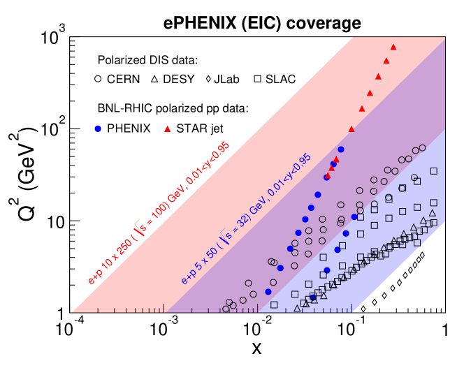
Deep Inelastic Scattering experiments over the last several decades have greatly enhanced our understanding of the proton substructure. Measurements with colliding beams at H1 and ZEUS at HERA have mapped out the momentum distributions of quarks and gluons, and shown that the gluons carry roughly half of the proton momentum. Fixed target experiments, with polarized nucleons and leptons at SLAC, CERN, DESY and JLab have revealed new surprises about proton structure, finding that only a small fraction of the proton spin comes from the quark spin and that there is significant correlation between the intrinsic motion of quarks and the nucleon spin. Measurements at both fixed target and colliders have started to image the proton through exclusive measurements.
eRHIC will greatly enhance the kinematic coverage for DIS with polarized beams, as shown in Figure 1.1. With the capabilities of ePHENIX, we will significantly extend our understanding of the proton. The gluon and flavor dependent sea quark spin contributions to the proton spin will be determined, as will the possible orbital angular momentum contributions. The spatial and momentum distributions of (sea) quarks and gluons can be mapped, giving a multidimensional description of the proton.
Longitudinal spin of the proton
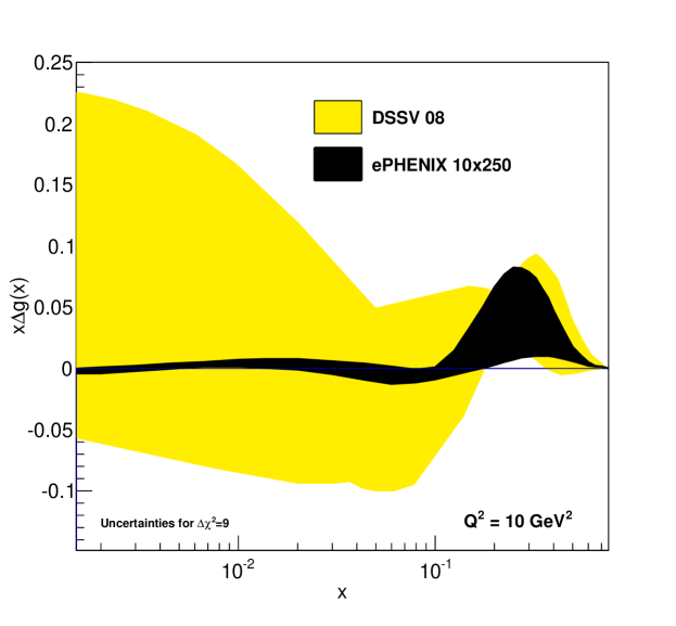
The puzzle of the proton spin, to which the quark spin only contributes roughly a third, has spurred two decades of study. Measurements from fixed target polarized DIS have determined the quark contribution, but are less sensitive to the gluon due to the small kinematic coverage. Current RHIC measurements indicate that the gluon spin contribution may be comparable or even larger than the quark spin contribution, but due to the limited coverage at low longitudinal momentum fraction, , large uncertainty remains, as is shown in Figure 1.2 (yellow band).
Determining the gluon longitudinal spin contribution is a primary goal of the EIC and of ePHENIX, and will be possible due to the large reach in and four-momentum transfer squared, . Figure 1.2 shows the expected impact from ePHENIX measurements of inclusive DIS on the uncertainty of the gluon helicity distribution as a function of .
With the ePHENIX particle identification (PID) detectors, measurements of pions and kaons will greatly improve on the determination of the sea quark longitudinal spin distribution as well, including that of the strange quark, , which has been of particular interest in the last few decades, because of the contradictory results obtained from different data. Current global analyses use hyperon beta decay to constrain , which indicates a negative value for the full integral over . Fixed target SIDIS measurements of kaon asymmetries, which directly probe , though at low values of and in a limited range, find a positive contribution for . eRHIC provides data over a wide and range. Further, ePHENIX will provide excellent particle ID capability to identify kaons and allow direct measurements of strangeness spin contribution to the nucleon down to .
Transverse motion of quarks and gluons in the proton
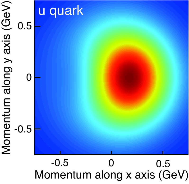
Large transverse spin asymmetries measured in fixed target SIDIS in the past decade have spurred significant theoretical work. These asymmetries relate to the transversity distribution, the correlation between the transverse spin of the proton and a transversely polarized quark in it, and Transverse Momentum Distributions (TMDs), such as the Sivers or Boer-Mulders distributions, which describe correlations between either the proton or quark spin and the quark intrinsic motion, specifically the transverse momentum of the quark. With measurements of identified pions and kaons, these asymmetries give a 21 dimensional description of the spin and momentum distributions of different quark flavors in the proton, such as is shown in Figure 1.3.
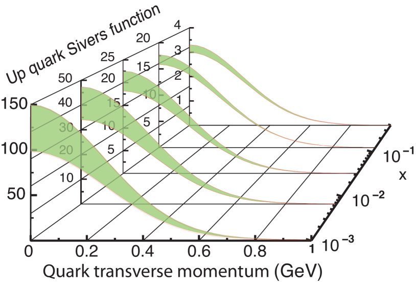
Current measurements, however, are only able to probe a small region in and , limiting the description to the valence quark region. Understanding of how the sea quarks and gluons contribute requires a larger kinematic range, such as provided at eRHIC. With the PID capabilities of ePHENIX, asymmetry measurements with transversely polarized nucleons and electrons in SIDIS will enable the study of these TMDs over most of this range, significantly expanding our knowledge of the proton structure. The constraint on the Sivers distributions was discussed in the EIC White Paper [3], with the expectations shown in Figure 1.3. For the first time, determination of the Sivers distribution over a wide range in will be possible, including the low region where gluons dominate.
The transversity distribution, when coupled with the Collins fragmentation asymmetry, would result in an azimuthal asymmetry in the hadron production. This has been called the Collins effect, and is a measurement that goes to the heart of establishing the transversity distribution in a proton [6]. Measurement over the wide kinematic region would not only allow us to measure transversity, but the wide -coverage possible at eRHIC would afford the first reliable measurement of the tensor charge of the proton (the integral over of the transversity distribution). No other currently operational or planned facility can do this.
Tomographic imaging of the proton
Hard exclusive processes such as the Deeply Virtual Compton Scattering (DVCS) and Deeply Virtual Vector Meson production (DVVM) involve interactions between the virtual photon and the partons in the proton without breaking the proton, resulting in the production of a real photon in DVCS or a vector meson in DVVM processes. Just as elastic lepton-nucleon scattering gives information on the spatial distribution of the electric charge and magnetization in the nucleon, DVCS and DVVM processes probe the transverse distribution of quarks, anti-quarks and gluons. This information is encoded in generalized parton distributions (GPDs), which quantify the distributions of quarks and gluons in terms of their positions in the transverse plane and longitudinal momentum fraction, providing 21 dimensional imaging of the nucleon. Measurements with polarized beams enable studies of spin-orbit correlations of quarks and gluons in the nucleon, by correlating the shift in the parton transverse distribution and proton transverse polarization. It is intuitively connected with orbital angular momentum carried by partons in the nucleon and hence of great interest in addressing the nucleon spin puzzle (nucleon spin decomposition) [7].
The existing data on GPDs from fixed target experiments cover only a limited kinematical range of (the squared momentum transfer to the proton), medium to high and low . The is connected through the Fourier transform with the impact parameter range probed. While data from HERA collider experiments (ZEUS and H1) covered lower and a wide range in , they are statistically limited. Furthermore, the HERA proton beams were unpolarized, so ZEUS and H1 were not able to study the proton-spin dependence in these measurements. With its large acceptance, excellent detection capabilities, high luminosity and broad range of energies of the polarized proton/helium beams available at eRHIC, ePHENIX will provide high precision data over a wide range of , and . The wide range in possible at eRHIC is of crucial importance, and will be achieved by integrating Roman Pot detectors in the accelerator lattice from the outset. Similar measurements performed with ion beams will allow analogous imaging of nuclei, allowing the first look at the parton distributions inside the nuclei.
The EIC White Paper demonstrates the precision that can be achieved in such a program with Deeply Virtual Compton Scattering (DVCS) and exclusive production. The detector requirements for such measurements discussed in the White Paper and what we propose as ePHENIX are similar. For such, we expect ePHENIX will be able to make high impact measurements of GPDs.
1.3.2 Nucleus as a laboratory for QCD
Electron scattering interactions from nuclei allow key tests of the modification of parton distribution functions in nuclei of various sizes. The EIC has the unprecedented energy reach to probe deep into the low- quark and gluon region where there are predictions of significant non-linear evolution effects and possibly the realization of a universal state of the QCD vacuum at high gluon density. In addition, rather than looking at the modified number of deep inelastic scatterings, one can study via SIDIS the changes in the process of a highly virtual struck quark to color neutralize and eventually hadronize when in the presence of a nuclear medium.
Hadronization and its modification in nuclear matter
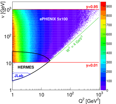
Deep inelastic scattering with heavy nuclear targets provides an effective stop watch and meter stick with which one can measure the color neutralization and hadronization times, and understand important details of partonic interactions with the nucleus. By varying the size of the nuclear target (at eRHIC all the way up to uranium) and changing key DIS parameters () one can calibrate this watch and meter stick. Figure 1.4 shows the kinematic reach for 5 GeV electrons scattering from 100 GeV/nucleon heavy nuclei in terms of the initial virtuality and the energy of the struck quark in the nuclear rest frame . Earlier experiments with fixed targets have measured very interesting modifications in apparent fragmentation functions, and yet those results are limited to small values of and . In the case of the published HERMES results [8] in Fig. 1.4, one observes a dramatic decrease in the number of high- hadrons (those with a large fraction of the struck quark momentum) in scattering from nuclear targets. There are many possible explanations of the experimental results, including parton energy loss due to multiple scattering in the nucleus and induced gluon radiation — a similar mechanism has been used to explain the “jet quenching” phenomena discovered in heavy ion collisions at RHIC. Other theoretical frameworks predict a strong correlation between a short color neutralization timescale and high- resulting processes. An excellent review of the various theoretical approaches is given in Ref. [9]. Figure 1.4 also shows the expected statistical precision with the ePHENIX PID capabilities over the full range in one bin.

If the struck quark remains an undressed color charge while it traverses the nucleus, one might expect that the ratio of final state hadrons ( and their anti-particles) would show the same degree of nuclear modification. Shown in the right panel of Figure 1.4 are the double ratios of modifications with a xenon target for antiprotons to protons and to . It is notable that there is a larger suppression for the hadrons with a larger cross section with nucleons (e.g. and ). If this is due to hadronization occurring within the nucleus, then inelastic collisions can result in the differential attenuation. How does this attenuation vary with the energy of the struck quark? The EIC realization has the enormous reach in the energy of the struck quark at fixed to measure the full evolution with high statistics. As demonstrated in this document, ePHENIX will have excellent particle identification to make exactly this measurement with high statistics. In addition, one can vary the virtuality which is also expected to play a significant role in the length scale probed in the nucleus and thus rate of initial radiation.
Tests with charm mesons via displaced vertex measurements are not in the initial suite of ePHENIX capabilities, and could be added with a later inner thin silicon detector. Measurements of the interactions of charm quarks with the nucleus would be quite interesting in the context of suppressed radiation due to the “dead-cone” effect. However, the relation to kinematic variables and may depend on the balance of DIS events from intrinsic charm as opposed to photon-gluon fusion reactions resulting in pair production.
QCD matter at extreme gluon density
A key goal of any future EIC is to explore the gluonic matter at low , where it is anticipated that the density of gluons will saturate as the rate of gluon recombination balances that of gluon splitting. In fact, there are well known modifications to the quark distribution functions in nuclei that have significant dependence: high Fermi motion effects, then the EMC suppression, anti-shadowing enhancement, and finally nuclear shadowing at the lowest . The ePHENIX detector, combined with the large kinematic reach of an A collider, is in an excellent position to map this physics out in the gluon sector.
The lowest regime with saturated gluon densities is unique to QCD, as gluons carry the QCD charge, “color”, and so interact with themselves. In order to explore this saturation region, one must probe nuclear matter at high center-of-mass energy, so as to reach as low in as possible while still in the perturbative QCD regime (i.e., GeV2). Generally, a saturation scale, , is defined to indicate the onset of saturation (where the gluon splitting and recombination balance each other), with falling as increases. In reality the point at which recombination starts to balance the gluon splitting is a range in and and so making measurements over a wide range in and is necessary to fully understand these effects.
eRHIC will have a significantly lower center-of-mass energy than HERA, and so cannot improve upon the minimum probed with measurements in . However, eRHIC will also be capable of accelerating heavy ions in A collisions. As the probed is related to the resolution of the probe, collisions at the same can resolve significantly lower due to the larger extent of the nucleus: the partons in the highly accelerated nucleus are probed coherently. This effectively reduces the probed in A collisions by a factor of , with the atomic weight, as this is proportional to the size of the nucleus. At the energies planned for eRHIC, based on measurements in A, one expects saturation effects in inclusive DIS in A.

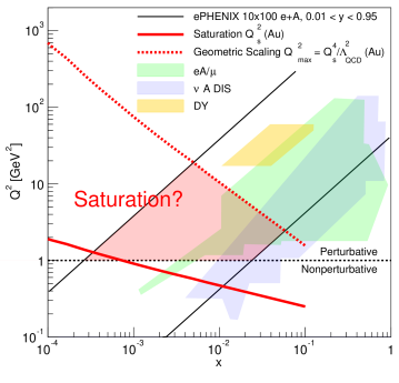
Figure 1.5 shows the and coverage of ePHENIX for the 10 GeV 100 GeV/nucleon configuration compared with the current fixed target data. Two red lines are drawn, one (solid) showing expectations of in Au and the other (dashed) showing the expected turn on of geometric scaling, which relates to the saturation scale by . The shaded red region is where ePHENIX can search for saturation effects.
As described in the EIC White Paper [3], it can be even more effective to explore this region of dense gluonic matter with diffractive physics, where at least two gluons are exchanged in the interaction. Therefore, a primary measurement to probe saturation effects at eRHIC will be comparing the diffractive-to-total cross-section from and A. The ratio of these cross-sections will directly relate to the size of any saturation effects. Figure 1.6, taken from the EIC white paper [3], shows the prediction of one saturation model for this cross-section ratio with and without saturation, indicating large possible effects. Note that the statistical and systematic uncertainties in this plot are scaled up by a factor of 10 in order to be visible. This measurement relies on measuring events with a large rapidity gap, which is the signature of diffractive events due to the fact that the hadron remains intact after the scattering (though in the case of ions, the nucleus may still break up). The ePHENIX detector will have wide calorimetric coverage, and so will be able to make a measurement of the ratio of diffractive-to-total cross-sections with comparable precision as shown in Figure 1.6.
Chapter 2 Detector Requirements
The detector requirements for Deep Inelastic Scattering measurements are well established by previous DIS experiments (H1, ZEUS, HERMES, COMPASS, etc.), by EIC group studies [3, 9], and through work by the eRHIC Task Force [12]. Table 2.1 summarizes these basic requirements and how ePHENIX would meet them. After a brief overview of the relevant kinematic variables, detailed studies are presented in this chapter.
| Detector requirements | Detector solution |
|---|---|
|
Electron-ID:
High purity ( 99%) identification of the scattered lepton over hadron and photon background Important for electron-going direction and barrel acceptance |
Electromagnetic Calorimetry and charged particle tracking
Minimum material budget before EMCal Good energy and tracking resolution for matching |
|
Resolution in and :
Excellent momentum and angle resolution of the scattered lepton to provide high survival probability ( 80%) in each (,) bin (important for unfolding) Important for electron-going direction and barrel acceptance |
High resolution EMCal and tracking in electron-going direction
Good (tracking) momentum resolution for GeV in barrel Good (EMCal) energy resolution for GeV in barrel |
|
Hadron identification:
efficiency and purity |
In barrel acceptance: DIRC for GeV/c
In hadron-going direction: Aerogel for lower momentum and gas RICH for higher momentum |
|
Wide acceptance for leptons and photons in DVCS:
Ability to measure DVCS lepton and photon within |
EMCal and tracking with good resolution over for lepton and photon measurements covering |
|
Electron/Photon separation:
Separate DVCS photon and electron in electron-going direction |
High granularity EMCal in electron-going direction |
| Measurement of scattered proton in exclusive processes | Roman pots in hadron-going direction |
|
”Rapidity gap” measurement capabilities:
Measure particles in for diffractive event identification |
Hadronic calorimetry covering , and EMCal covering |
|
Forward Zero-Degree calorimetry:
Measure neutrons from nucleus breakup in diffractive A events |
Zero-Degree calorimeter in hadron-going direction planned, in coordination with CAD |
The suggested ePHENIX detector configuration is shown in Figure 1. It is built around the sPHENIX detector, which is a superconducting solenoid and electromagnetic and hadronic calorimeter in the central region ( for pseudorapidity ). This proposal would add to that detector the following detector subsystems:
- electron-going direction ():
-
High resolution Crystal EMCal with GEM tracking.
- Barrel ():
-
Compact-TPC for low mass tracking and PID for momentum GeV/c with DIRC
- hadron-going direction ():
-
Hadronic and Electromagentic calorimeters, GEM trackers, and Aerogel-based () and gas-based RICH for PID up to momentum GeV.
- Far-Forward in hadron-going direction:
-
Roman Pots and Zero-Degree Calorimeter.
2.1 Kinematics
In DIS, a lepton is scattered off a target hadron via the exchange of a virtual boson, which for electron beam energy GeV can always be taken as a virtual photon. Defining the four-momenta of the incoming and scattered electron and the incoming proton as , and respectively, we can define the following Lorentz invariant quantities:
| (2.1) | |||||||
| (2.2) | |||||||
| (2.3) | |||||||
| (2.4) | |||||||
| (2.5) |
where is the center-of-mass energy squared, is the 4-momentum transferred from scattered electron and is the virtuality of the photon which gives the resolution scale of the scattering, is the inelasticity of the scattering and is Bjorken , the fractional momentum carried by the struck parton. Here, we have also written these in the lab frame in terms of the measured scattering angle, and the energies of the proton and incoming and scattered electron, , and , respectively, under the approximation that the electron and proton mass are small compared to the beam energies.
For inclusive DIS, where only the kinematics of the scattered lepton are measured, Eq. 2.1–2.5 fully describe the event. For SIDIS, in which a final state hadron is also measured, additional variables are needed. The fraction of the scattered parton’s momentum carried by the hadron is defined as
| (2.6) |
where is the four-momentum of the measured hadron. Further, we can define as the transverse momentum of the hadron w.r.t. the virtual photon, in the center-of-mass frame of the proton (or ion) and virtual photon.
For exclusive processes, in addition to the scattered lepton, the final state photon in DVCS or meson in Deeply Virtual Meson Production as well as the scattered proton are measured. In this case, another kinematic variable is introduced – the squared momentum transfer to the proton, , defined as
| (2.7) |
where is the four-momentum of the scattered proton.
2.2 Inclusive DIS and scattered electron measurements
In inclusive DIS, where only the kinematics of the scattered electron are necessary, the primary requirements of any detector are electron identification and sufficient resolution in and , which in turn mandates good energy and angle resolution for the scattered electron measurements (Eq. 2.2–2.4).
2.2.1 Electron Identification
In collider geometry, the DIS electrons are scattered mainly in the electron-going direction and central rapidities (barrel acceptance), see Figure 2.1. Central rapidity selects scatterings with higher and higher (due to its correlation with ). The higher the electron beam energy, the more scattering there is in the electron-going direction. The energy of the scattered electron varies in the range from zero up to the electron beam energy and even to higher values for electrons detected in the barrel acceptance, see Figure 2.1.

Collider kinematics allow clear separation of the scattered electrons from other DIS fragments — hadrons and their decay products — which are detected preferably in the hadron-going direction, leaving much softer spectra in the central region and the electron-going direction. Figure 2.2 shows scattered electron momentum spectra along with photon (mainly from hadron decays) and charged pion spectra. For the 10 GeV electron beam, hadronic and photonic backgrounds are small above GeV/c, but increase rapidly at lower momenta.

The different response of the EMCal to hadrons and electrons, along with a direct comparison of energy deposited in the EMCal and momentum measured in the tracking system (i.e., matching) provides a significant suppression of hadronic background in DIS scattered electron measurements: from a factor of 20–30 at momenta near 1 GeV/c to a factor of greater than 100 for momenta above 3 GeV/. Figure 2.3 shows the effectiveness of electron identification with the EMCal and tracking, providing high purity for DIS scattered electron measurements at momenta 3 GeV/ for the 10 GeV electron beam (and 1.5 GeV/ for the 5 GeV electron beam). The evaluations above are done with a parametrized response of the EMCal to hadrons and electrons, and EMCal and tracking resolutions described in Sections 3.3 and 3.2. Further enhanced electron identification is expected from the use of the transverse shower profile. We are also studying possible electron identification improvement with longitudinal segmentation in the crystal calorimeter in the electron-going direction. These are expected to move the detector capabilities for high purity electron identification down to 2 GeV/c (1 GeV/c) for 10 GeV (5 GeV) electron beam, which only marginally limits the space probed in our measurements, see Figure 2.4.


Photon conversion in material between the collision point and the tracker (mainly beam pipe, with thickness as small as of radiation length) is not expected to contribute sizable background. Moreover, conversion electron-positron pairs will be well identified by our tracking system in the magnetic field and additionally suppressed by E/p matching cut. A detailed GEANT simulation study is ongoing to quantify this effect.
2.2.2 Resolution in and and bin survival probability
Measurements of the scattered electron energy and polar angle impact the DIS kinematic reconstruction, Eq. 2.2–2.4. Unfolding techniques are generally used to correct for smearing in due to detector effects, and the effectiveness of this technique depends on the degree to which events migrate from their true bin to another. This migration can be characterized by the likelihood of an event remaining in its true bin — the bin survival probability.
The energy resolution is directly propagated to , so that . The EMCal energy and tracking momentum resolutions will provide excellent precision for measurements. Conversely, the resolution is magnified by a factor of as , and so the energy resolution in this approach effectively defines the limit of our kinematic reach at low y.
Figure 2.5 shows the relative resolution in and measurements using the standard “electron” method, in which the scattered electron is measured. While the relative uncertainty, , is better than 10% over whole - acceptance, the relative uncertainty on , , clearly demonstrates its -dependence (the same points are on the diagonal, as from Eq. 2.4, ). The step in resolution around GeV2 in these plots corresponds to the transition from the electron-going direction to the barrel acceptance, which differ mainly in the resolution of the different electromagnetic calorimeters covering those two regions of the acceptance. All of this translates to the statistics survival probability in a bin shown in Figure 2.6, which is calculated for five bins per decade in each of and . The survival probability is for in the electron-going direction and for in the barrel acceptance.

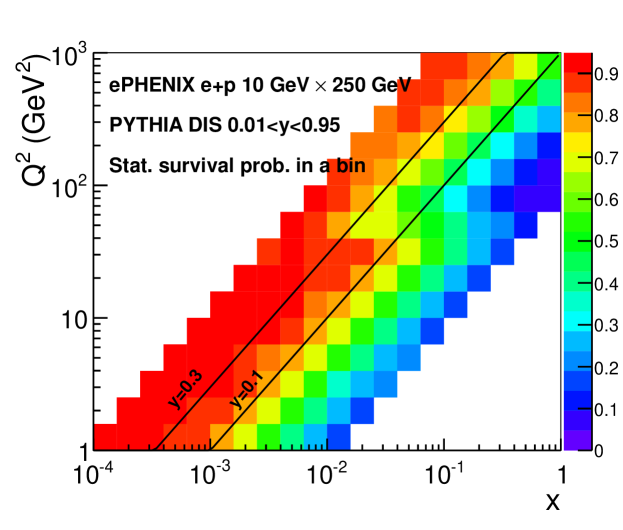
The effect of the polar angle resolution in Eq. 2.2–2.4, is the biggest for forward scattering (small ). It was found that crystal EMCal position resolution (better than 3 mm for GeV electrons, see Chapter 3.3.1) provides enough precision for scattered electron angle measurements, so that it affects the statistics migration in bins on Figure 2.6 only marginally.
The Jacquet-Blondel method using the hadronic final state is an alternative approach to reconstruct DIS kinematics. Its resolution for inelasticity , and hence for , is nearly flat, so it provides much better precision for determination than the “electron” method, in the region with small . It is also better in the higher region corresponding to the barrel acceptance, where the resolution of the “electron” method is limited by the EMCal resolution.
The Jacquet-Blondel method requires the measurement of all final state hadrons produced in or A scattering. A study with the Pythia generator shows that the precision of this approach does not deteriorate if the hadron detection capabilities are limited to . This method provides relative precision for the measurement of of better than 20%, which satisfies the bin statistics migration criteria discussed above. It was found that for the precision of this approach deteriorates only slightly when hadron measurements are limited to the barrel and forward acceptance (the acceptances we plan to equip with hadron identification capabilities, see Chapter 3.5). As was shown above, measurements at higher are well provided by the “electron” method.
Therefore, combining the electron and hadronic final state measurements provides precise determination of basic kinematic variable , and in the whole kinematical space.
QED radiative effects (radiation of real or virtual photons) are another source of smearing which is usually corrected with unfolding techniques. Unlike energy-momentum resolutions which introduces Gaussian-like smearing, radiative corrections are tail-like. They can be responsible for as much as 10–20% of statistics migrating away from a bin, and dominate over energy-momentum smearing at higher (compare to Figure 2.6).
2.3 Semi-inclusive DIS and hadron ID
As was discussed in Chapter 1, measurements of hadrons in SIDIS events are necessary to determine both the (sea)quark separated helicity distributions and TMDs. It is also important for understanding the hadronization process in nuclear matter. For these measurements, one needs to identify the hadron, particularly in the case of pions and kaons. In this section, we discuss the kinematic ranges of interest for pions, kaons and protons, and in Chapter 3, we discuss technology choices which can effectively make these measurements.
Figure 2.7 shows the yields of positively charged hadrons as a function of momentum and pseudorapidity for the 10 GeV 250 GeV beam configuration. A minimum cut of to remove soft physics effects and beam remnant is applied. For , the hadron momenta are limited by the electron beam momentum, while in the hadron-going direction, the hadron momenta extend almost to the full proton beam energy. The results are similar for other beam energy configurations.
As was stated above, ePHENIX will have three PID systems: (1) a DIRC covering providing - separation below 3.5–4 GeV/ (depending on purity and efficiency requirements), (2) an aerogel based RICH covering providing - (-) separation below 6 (10) GeV/ and (3) a gas based RICH covering providing - separation for GeV/ and separation for GeV/ (depending on the balance between efficiency and purity chosen). Based on these numbers, the PID for kaons would cover the and region outlined in black in Figure 2.7. The resulting ePHENIX and coverage for SIDIS events with an identified kaon is shown in Figure 2.8, for low () and high () bins, along with lines indicating the accessible DIS range ().
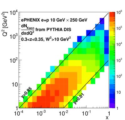

Figure 2.9 shows the impact on the and coverage of removing one of the three PID detectors planned for ePHENIX at low and high . The plots show the ratio of kaon yields when using only two PID detectors to those with all three detectors (i.e., standard ePHENIX). If the gas-based RICH detector is removed (left), the high reach, particularly at high , is lost. If the aerogel-based RICH is removed (middle), sensitivity to the region of moderate , and is lost. Finally, if the DIRC is removed, significant kinematic coverage at low , as well as moderate and high is lost. To achieve a wide and coverage, all three detectors are necessary. Extending the aerogel-based RICH to does not extend the kinematic coverage; the momentum range covered by such a detector corresponds to very low values of .

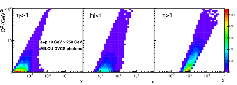
2.4 Exclusive DIS
Among exclusive processes, Deeply Virtual Compton Scattering (DVCS) is of special interest (see Chapter 1.3.1). The produced DVCS photon energy versus pseudorapidity distribution is shown in Figure 2.10. Most of the photons fall in the electron-going direction and the barrel (central rapidity) acceptance. The photon energy for varies in the range –4 GeV/ and is nearly independent of the beam energy in the range considered for eRHIC. Photons in the electron-going direction are more correlated with the electron beam and have energy from 1 GeV up to electron beam energy.

Figure 2.11 shows the - range covered by DVCS measurements for different rapidity ranges, emphasizing the importance of measurements over a wide rapidity range. Wide kinematical coverage is also important for separating DVCS events from Bethe-Heitler (BH) events (when a photon is radiated from the initial or final state lepton), which share the same final state. This can be done by utilizing the different kinematic distributions of DVCS and BH photons (e.g., in rapidity and inelasticity ). The planned EMCal and tracking cover (Chapter 3.3 and 3.2) and will provide excellent capabilities for DVCS measurements.
To ensure the reliable separation of electromagnetic showers in the EMCal from the scattered electron and the DVCS photon, sufficient EMCal granularity is necessary. The minimal angle separation between the electron and the photon is reached for electrons with the smallest scattering angle (i.e., the smallest ) and is inversely proportional to electron beam energy. For a 10 GeV electron beam and GeV2, the minimum angle is rad. The proposed crystal EMCal in the electron-going direction, with granularity rad (see Chapter 3.3.1), will provide the necessary electron and photon shower separation.
It is also important to ensure the exclusiveness of the DVCS measurements, and so it is highly desirable to reconstruct the scattered beam proton. The proton scattering angle is inversely proportional to proton beam energy and varies from 0 to 5 mrad for 250 GeV proton beam and four-momentum transfer GeV2. It can be detected with the planned ”Roman Pots” detectors located along the beam line (See Chapter 3.6).
2.5 Diffractive measurements
Diffractive event measurements play an important role in nucleon and nucleus imaging. They are particularly sensitive to the gluon distribution in nuclei and hence to gluon saturation phenomena. Diffractive events are characterized by a rapidity gap, i.e. an angular region in the direction of the scattered proton or nucleus devoid of other particles. Figure 2.12 shows the pseudorapidity distribution for the most forward going particle in DIS events and in diffractive events. Extending the forward acceptance of the detector to and beyond is important if one is to have good capability using the rapidity gap method for detecting diffractive events and to separate them from DIS processes.

The planned ePHENIX EMCal and tracking coverage of and hadronic calorimetry coverage of are expected to provide excellent identification capabilities for diffractive events. In addition, to separate coherent (the nucleus remains intact) and incoherent (the nucleus excites and breaks up) diffractive events, we plan to place a zero degree calorimeter after the first RHIC dipole magnet (see Chapter 3.6), which is expected to be very efficient at detecting nuclear break-up by measuring the emitted neutrons.
Chapter 3 Detector Concept
A full engineering rendering of ePHENIX is shown in Figure 3.1. The drawing shows the ePHENIX detector in the existing PHENIX experimental hall and illustrates the reuse of the superconducting solenoid and the electromagnetic and hadronic calorimeter system of sPHENIX. The rendering also shows the final eRHIC focusing quadrupoles, each located 4.5 m from the interaction point (IP). Those magnets and the height of the beam pipe above the concrete floor, set the dominant physical constraints on the allowable dimensions of ePHENIX. This Chapter will describe the ePHENIX detector concept in terms of its component subdetectors and their expected performance.

The ePHENIX detector consists of a superconducting solenoid with excellent tracking and particle identification capabilities covering a large pseudorapidity range, as shown in Figure 3.2. It builds upon an excellent foundation provided by the proposed sPHENIX upgrade [1] detailed in the MIE proposal submitted to the DOE Office of Nuclear Physics by Brookhaven National Laboratory in April 2013. The strong sPHENIX focus on jets for studying the strongly-coupled quark-gluon plasma in , /A and AA is enabled by excellent electromagnetic and hadronic calorimetry in the central region ().
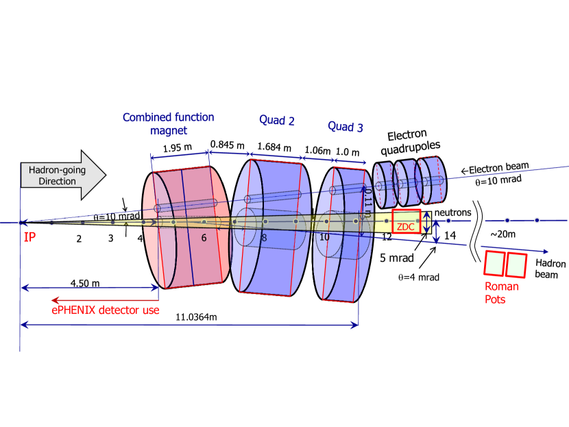
The C-AD Interaction Region (IR) design at the time the Letter of Intent charge was issued had the final focusing quadrupoles of the accelerator positioned m from the IP and employed a “crab crossing” to maintain high luminosity while allowing the electron and hadron beams to intersect at an angle of 10 mr (see Figure 3.14). The ePHENIX detector concept shown in Figure 3.1 and Figure 3.2 respects these constraints. For instance, the hadronic calorimeter in the hadron-going direction fits within the 4.5 m constraint imposed by the accelerator magnets, and the detector is aligned so that the electron beam travels along the symmetry axis of the magnetic field. Clearly, the progress of ePHENIX from concept to final design will be done in close consultation with C-AD to ensure that the design of IR and the design of the detector remain synchronized.
We have an extensive Geant4 description of the ePHENIX detector, based on the same software framework as used in PHENIX and sPHENIX, which enables ready use of many existing PHENIX software analysis tools. An example of running a DIS event through the Geant4 detector description is shown in Figure 3.3.

The DOE funded sPHENIX subsystems which will be reused in ePHENIX are:
- Superconducting solenoid:
-
The sPHENIX detector concept reuses the BaBar superconducting solenoid to provide a 1.5 Tesla longitudinal tracking magnetic field. Its field is shaped in the forward directions with an updated yoke design in the ePHENIX detector as discussed in Section 3.1.
- Electromagnetic calorimeter:
-
A tungsten-scintillator sampling electromagnetic calorimeter with silicon photomultipliers (SiPMs) enables a compact barrel calorimeter positioned inside the bore of the superconducting solenoid. The calorimeter system provides full azimuthal coverage for with an energy resolution of . The readout is segmented into towers measuring roughly .
- Hadronic calorimeter:
-
A -depth hadron calorimeter surrounds the solenoid. An iron-plate and scintillator sampling design provides an energy resolution of better than with full azimuthal coverage. It also serves as part of the magnetic flux return for the solenoid.
In addition, new subsystems will be added to the ePHENIX detector, which will be further discussed in this chapter. These subsystems include:
- Electron going direction:
- Central barrel:
-
Fast, compact TPC tracker and DIRC
- Hadron going direction:
-
GEM tracking system, gas-based RICH, aerogel-based RICH, beam-beam counter (BBC), electromagnetic and hadron calorimeter
- Beam line of hadron-going direction:
-
Roman pot detectors and a zero-degree calorimeter
3.1 Magnet system
| Central Induction | 1.5 T |
|---|---|
| Winding structure | 2 layers, higher current density at both ends |
| Winding axial length | 3512 mm |
| Winding mean radius | 1530 mm |
| BaBar operation current | 4596 A, 33% of critical current |
| Total turns | 1067 |
As with sPHENIX, ePHENIX is based around the BaBar superconducting solenoid [15] with no modifications to its inner structure. The major specifications for its coil are listed in Table 3.1. A notable feature of the BaBar magnet is that the current density of the solenoid can be varied along its length, i.e., lower current density in the central region and higher current density at both ends. This is accomplished by using narrower windings (5 mm) for the last 1 m at both ends. The central winding uses 8.4 mm-width coils [15]. The main purpose of the graded current density is to maintain a high field uniformity in the bore of the solenoid, which is also a benefit for ePHENIX. This design feature enhances the momentum analyzing power in both the electron-going and hadron-going directions.
A magnetic flux return system, consisting of the forward steel/scintillator hadron calorimeter, a flaring steel lampshade, and a steel endcap not only returns the flux generated by the solenoid, but shapes the field in order to aid the momentum determination for particles in the hadron-going and electron-going directions. As shown in Figure 3.2, the flux return system consists of the following major components:
-
•
Forward steel/scintillator hadron calorimeter, at to m
-
•
Steel flux shaping lampshade, along the line
-
•
Barrel steel/scintillator hadron calorimeter, from to m
-
•
Steel end cap, at to m and cm
The magnetic field lines were calculated and cross checked using three different 2D magnetic field solvers (POISSION, FEM, and OPERA) and are shown in Figure 3.2. In the central region, a 1.5 Tesla central field along the electron beam direction is produced. The field strength variation within the central tracking volume is less than .
3.2 Vertex and Tracking

The -location of the primary event vertex will be determined using a timing system enabling a precision of mm. The ePHENIX tracking system utilizes a combination of GEM and TPC trackers to cover the pseudorapidity range of . The momentum resolution for the full device is summarized in Figure 3.4.
3.2.1 Event vertex measurement
The vertex information is used for the determination of photon kinematics and for assisting the track fitting. Precise vertex information is important for momentum determination in the electron-going direction, where tight space constraints limit the possible number of tracking planes. The location of the vertex will be measured by:
-
•
For non-exclusive processes, we propose to identify the -location for the vertex using timing information from a BBC detector in the hadron-going direction in coincidence with the electron beam RF timing. The BBC detector covers –5 at m. A timing resolution of 30 ps or better enables the measurement of the vertex with resolution of mm. It leads to a sub-dominant error for the momentum determination for the electron-going direction (%). This timing resolution can be provided by the existing technology of Multigap Resistive Plate Chamber (MRPC) [16] or by microchannel plate detectors (MCP) photomultiplier [17] with a thin quartz Čerenkov radiator, a technology which is under active current development.
-
•
We plan to measure the average transverse beam position by accumulating tracking information over the course of a one hour run. The statistical precision for the beam center determination is expected to be much smaller than the distribution of the transverse collision profile ( m), and therefore a negligible contribution to the uncertainty for event-by-event vertex determination.
3.2.2 Tracking in the central region,
A fast, compact Time Projection Chamber (TPC) will be used for tracking in the central region, occupying the central tracking volume of –80 cm and cm and covering . A TPC will provide multiple high resolution space point measurements with a minimal amount of mass and multiple scattering. The design is based on a GEM readout TPC, similar to a number of TPCs that have either already been built or are currently under design. For example, the LEGS TPC [18] utilized a fine chevron-type readout pattern with a pad size of 2 mm 5 mm and achieved a spatial resolution 200 m. The use of such a readout pattern helps minimize the total channel count for the electronics and hence the total cost. The GEM TPC upgrade for ALICE [19, 20] and the large GEM readout TPC for ILC [21, 22] are other examples of large GEM TPCs that have recently been studied.
It is assumed that the TPC will have a single high voltage plane at cm and be read out on both ends, resulting in a maximum drift distance cm. It will use a gas mixture with a fast drift time, such as 80% argon, 10% CF4 and 10% CO2, which, at an electrical field of 650 V/m, achieves a drift speed cm/s, and would result in a maximum drift time of 10 s. With a position resolution of m and 65 readout rows, the expected transverse momentum resolution would be GeV for high momentum tracks.
3.2.3 Tracking in hadron-going direction,
The design of the magnetic flux return enables tracking in the hadron-going direction in the main and fringe fields of the BaBar magnet. Compared to a compact solenoid with no current density gradient, the BaBar magnet system improves the momentum analyzing power for forward tracks by about a factor of four due to two main factors: 1) the BaBar magnet has a length of 3.5 m, which provides a longer path length for magnetic bending; 2) the higher current density at the ends of the solenoid improves the magnetic field component transverse to forward tracks, and therefore provides higher analyzing power.
The tracking system at high in the hadron-going direction utilizes four stations of GEMs.
-
•
Station 1 consists of two planes with complementary coverages. They are located at and 60 cm, respectively, covering a radius of –15 cm.
-
•
Stations 2–4 are at , 200, 300 cm, respectively, covering –4.
The readout planes for these devices are optimized to preserve high position resolution in the azimuthal direction ( m in using a chevron-type readout with a pad size similar to the central TPC) and 10–100 mm in , while minimizing the readout channel cost. However, the - resolution can be improved to be better than 100 m, even for tracks at larger angles (up to 45 degrees), by the use of mini-drift GEM detectors, in which a small track segment, or vector, is measured for each track at each measuring station. These detectors, which are currently under development [23], would provide improved position resolution with less material and lower cost than multiple stations of planar GEM detectors. For this letter, we assumed that a high resolution GEM readout pattern (1 mm wide chevron-type readout) with a m for the inner tracking region (). For the outer tracking region (), mini-drift GEM with 2 mm chevron-type readout provide m. The momentum resolution is estimated in Figure 3.4.
It should be noted that the size of the GEM trackers for Stations 2–4 are quite large (–20 m2). It is currently challenging to produce such large GEM foils and to do so at an affordable cost. However, there has been substantial progress in this area in recent years at CERN due to the need for large area GEM detectors for the CMS Forward Upgrade [24]. CERN has developed a single mask etching technology which allows fabrication of very large area GEMs (up to 2 m 0.5 m), and they plan to transfer this technology to various commercial partners (such as Tech Etch in the US, which supplied the GEM foils for the STAR Forward GEM Detector). We anticipate being able to procure such large area GEM detectors by the time they are needed for EIC.
3.2.4 Tracking in the electron-going direction,
The electron direction tracking is designed to fit in the space limited by the DIRC ( cm) and the electromagnetic calorimeter ( cm). Three GEM tracking stations, located at , 55 and 98 cm, are used in combination with the TPC and vertex information to determine the momentum vector.
-
•
For to , TPC track segment and vertex are used
-
•
For to , vertex, TPC track segment, GEM station 1 and 3 are used.
-
•
For to , vertex, GEM station 2 and 3 are used.
Similar to the hadron-going direction, the position resolution for these detectors is 50 m for using 1 mm wide chevron-type readout. For , the mini-drift GEM technology [23] and 2 mm wide chevron-type readout provide m. The radial resolution is cm (stations 1 and 2) and cm (station 3). As shown in Figure 3.4, a momentum resolution of can be achieved for tracks of GeV and , which is sufficient for the calorimeter - matching cut for the electron identification. For DIS kinematics reconstruction the tracking radial resolution is not crucial as enough precision for scattered electron polar angle measurements will be provided by the EMCal, see Section 2.2.2.
3.3 Electromagnetic calorimeters
The ePHENIX detector will have full electromagnetic calorimeter coverage over . The sPHENIX barrel electromagnetic calorimeters will also be used in ePHENIX, covering with an energy resolution of . In addition, crystal and lead-scintillator electromagnetic calorimeter are planned for the electron-going and hadron-going direction, respectively. Optimization of the design of the barrel and endcap calorimeters will aim for uniform response in the overlap region between .
3.3.1 Crystal Electromagnetic calorimeter
The calorimeter on the electron-going side consists of an array of lead tungstate (PbWO4) crystals (commonly known as PWO), similar to the PANDA endcap crystal calorimeter shown in Figure 3.5 [25]. An enhanced light output version of lead tungstate (PWO-II) was chosen to provide high light yield ( p.e./MeV at room temperature) at a moderate cost ( € 5/cm3). It will provide an energy resolution %/ and position resolution better than in order to measure the scattered electron energy and angle in the electron-going direction down to low momentum with high precision.
The ePHENIX PWO calorimeter will consist of crystals, compared with 4400 crystals for the PANDA endcap, and will have a similar size and shape to the PANDA crystals. They will be (corresponding to one ) and will be read out with four SiPMs. This is different than the PANDA readout, which uses large area ( cm2) APDs. The SiPMs will provide higher gain, thus simplifying the readout electronics, and will utilize the same readout electronics as the other calorimeter systems in sPHENIX. It is also expected that the cost of SiPMs will be less than that of APDs covering the same area by the time they are needed for ePHENIX.
3.3.2 Lead-scintillator electromagnetic calorimeter
The electromagnetic calorimeter in the hadron-going direction consists of a lead-scintillating fiber sampling configuration, similar to the tungsten-scintillating fiber calorimeter in the central sPHENIX detector. Lead is used instead of tungsten in order to reduce the cost, but it is otherwise assumed to be of a similar geometry. It will cover the rapidity range from and have 0.3 sampling (2 mm lead plates) with 1 mm scintillating fibers, which will give an energy resolution %/. The segmentation and readout will also be similar to the central tungsten calorimeter, with towers (roughly 1 ) that are read out with SiPMs. This segmentation leads to K towers. By using the same type of readout as the central calorimeter, the front end electronics and readout system will also be similar, resulting in an overall cost savings for the combined calorimeter systems.
3.4 Hadron calorimeter
The hadron calorimeter in the hadron-going direction consists of a steel-scintillating tile design with wavelength shifting fiber readout, similar to the central sPHENIX hadron calorimeter. It will be thick and cover a rapidity range from . The steel in the absorber will also serve as part of the flux return for the solenoid magnet. The segmentation will be , resulting in towers. The readout will also be with SiPMs, similar to the central sPHENIX HCAL, which will again provide an advantage in being able to use a common readout for all of the calorimeter systems.
3.5 Hadron PID detectors

Hadron PID is planned for the hadron-going and barrel regions, covering . In the hadron-going direction, two PID detectors cover complementary momentum range: a gas-based RICH detector for the higher momentum tracks and an aerogel-based RICH detector for the lower momentum region. As in the BaBar experiment [26], a DIRC detector identifies hadron species in the central barrel. In addition, the TPC detector assists with PID by providing information for the low momentum region.
3.5.1 Gas RICH detector
High momentum hadron PID is provided by an optically focused RICH detector using a gas radiator. The main features for this RICH setup are
-
•
One meter of CF4 gas is used as the Čerenkov radiator. The pion, kaon and proton thresholds are 4, 15 and 29 GeV, respectively.
-
•
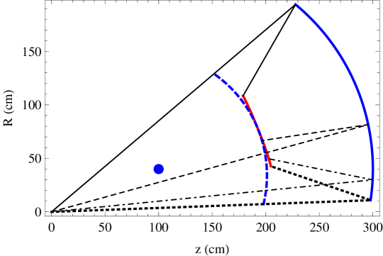
Čerenkov photons are focused to an approximately flat focal plane using spherical mirrors of 2 m radius, as shown in Figure 3.7. The geometric center of the mirror is at , as highlighted by the blue dot.
-
•
There are six azimuthal segmented RICH sextants.
-
•
The photon detector consists of CsI-coated GEM detectors [27], which are installed on the focal plane. The CsI coating converts the Čerenkov photons into electrons which are then amplified by the GEM layers and readout through mini-pads. The photon detector for each RICH sextant assumes a roughly triangle shape and covers an area of 0.3 m2.
Two distortion effects were estimated to be sub-dominant in error contributions for most cases:
-
•
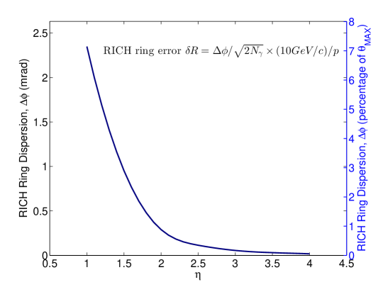
Strong residual magnetic field ( Tesla) are present in the RICH volume. This field will bend the tracks as they radiate photons, and therefore smear the Čerenkov ring in the azimuthal direction. However, the field design ensures that the field component is mostly parallel to the track inside RICH and therefore this smearing effect is minimized. The RMS size of the smearing, , is evaluated as in Figure 3.8. The uncertainty contribution to the RICH ring angular radius is , which is sub-dominant comparing to the photon measurement error for . The field contribution was included in the RICH performance estimation.
-
•
For tracks that originate from an off-center vertex, their focal point may be offset from the nominal focal plane as shown in Figure 3.7. The effect is dependent. For the most extreme case, that a track of originates from the vertex of cm (1.5 sigma of expected vertex width), an additional relative error of is contributed to the ring radius measurement, which averages over all vertices to below contribution. For high tracks, the difference is negligible comparing to the nominal RICH error.
We simulated the RICH performance with a radiator gas CF4 (index of refraction 1.00062). We use Pythia to generate the momentum distributions for pions, kaons, and protons. For each particle species, we use the momentum resolution and RICH angular resolution, to calculate the particle mass distribution. For higher momentum tracks the combined information from tracking system and energy deposit in HCal helps to improve momentum resolution particularly at higher rapidities, where momentum resolution from tracking degrades. For example, at pseudorapidity =4, the tracking momentum resolution for 50 GeV/c tracks is 50% (see Figure 3.4), while HCal can provide energy measurements with precision . Our simulation showed that the HCal is very effective in improving the resolution for high momentum track measurements even when this and other tracks (usually with lower momenta) are merged in a single cluster of deposited energy in HCal. In such a case, the contribution of lower energy tracks in HCal can be evaluated and subtracted based on momentum measurements in tracking system.
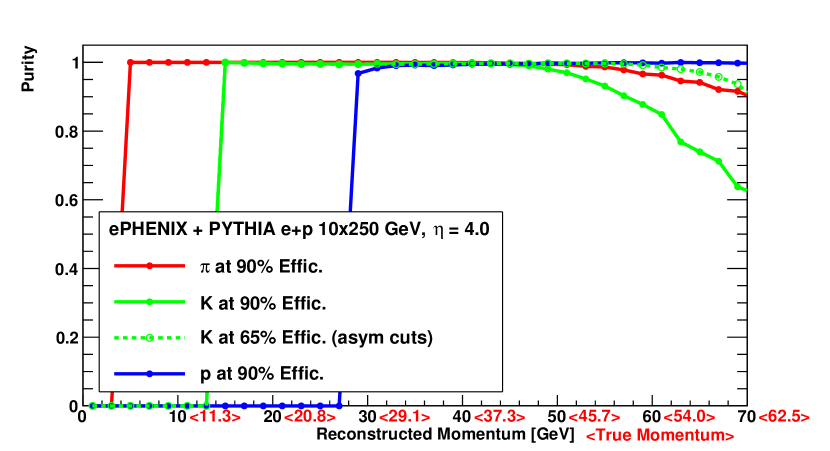
Figure 3.9 shows mass distributions for the most challenging high rapidity region =4 for different reconstructed track momenta. We make a symmetric 90% efficiency cut on the mass distributions, and calculate the purity for , shown in Figure 3.10. One can see high purity for all particle species up to momenta 50 GeV/c. Introducing asymmetric cuts on the mass distributions (and sacrificing some efficiency) extends further our capabilities for high purity hadron identification.
It is notable that the limitation on the mass resolution comes from the estimated 2.5% radius resolution per photon for the RICH from the EIC R&D RICH group. Our calculation includes the effect of the magnetic field distortion mentioned above, which is sub-dominant. This is a somewhat conservative estimate and LHCb and COMPASS have quoted values near 1% per photon. The R&D effort is working towards the best radius resolution, though there are challenges in having the light focus and readout within the gas volume in this configuration compared with LHCb or COMPASS.

3.5.2 Aerogel RICH detector
The aerogel detector will provide additional particle ID for kaons in the momentum range –15 GeV/c when used in conjunction with the gas RICH. Pions can be identified by the signal they produce in the gas RICH starting at a threshold of 4 GeV/c, and kaons will begin producing a signal in the aerogel at a threshold 3 GeV. Reconstructing a Čerenkov ring in the aerogel enables one to separate kaons from protons up to a momentum GeV/c with reduced efficiency above that.
Measuring a ring in the aerogel detector is a challenging technical problem for a number of reasons. Due to its relatively low light output, it will require detecting single photons in the visible wavelength range with high efficiency inside the rather strong fringe field of the superconducting solenoid. Also, due to the limited space available, it is difficult to have a strong focusing element in the RICH to focus the light into a ring in a short distance. One possibility for how this might be accomplished has been proposed by the Belle II experiment [28] and is shown in Figure 3.11. It uses several layers of aerogel with slightly different indices of refraction to achieve and approximate focusing of the light onto an image plane located behind the radiator. It should be possible to add additional layers of aerogel and optimize their thickness for producing the best quality ring for kaons using this technique, and therefore achieve good kaon-proton separation up to the highest momentum. One possibility for the photon detector would be large area Microchannel Plate detectors (MCPs), such as those being developed by the Large Area Picosecond Photodetector (LAPPD) Collaboration [17]. This effort is based on utilizing flat panel screen technology to produce large area MCPs at very low cost, while also preserving their excellent timing resolution (typically 20-30 ps). These devices would use multi-alkali photocathodes, which would be suitable for detecting the Cherenov light from aerogel with high efficiency, and also provide high gain for detecting single photoelectons. The excellent time resolution would also provide additional time of flight capability when used in conjunction with the BBC to further enhance hadron particle ID. While this is still an R&D effort, it has already produced very encouraging results and has substantial support within the high energy physics community, and we feel that this would offer an attractive low cost, high performance readout for the aerogel detector.
3.5.3 DIRC
The main form of particle ID in the central region will be provided by a DIRC (Detection of Internally Reflected Čerenkov Light). The DIRC will be located at a radius of cm and extend –10 cm in the radial direction. As we will be using the BaBar magnet for ePHENIX, it would be a major benefit to also acquire the BaBar DIRC, which was specifically designed to fit inside this magnet, and would completely satisfy the physics requirements for ePHENIX. However, since it is not certain at this time that the BaBar DIRC will be available for ePHENIX, we consider it more as a model for the type of DIRC that would be required in terms of its construction and performance.
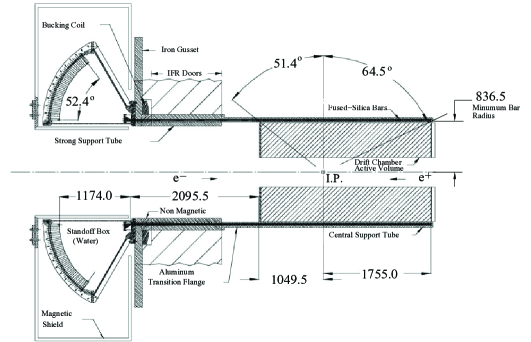
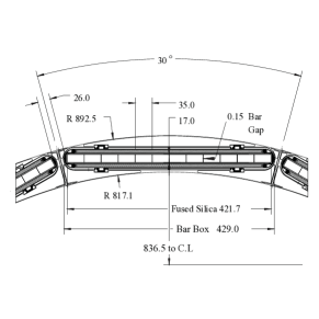
The BaBar DIRC, shown in Figure 3.12, consists of 144 precision fabricated quartz radiator bars that collect Čerenkov light produced by charged particles traversing the bars. In the BaBar DIRC, the quartz bars were read out on one end utilizing a large water filled expansion volume to allow the light to spread out and be read out using a large number (over 10,000) 28 mm diameter photomultiplier tubes.
The BaBar design, while allowing for a conventional PMT readout without the use of any focusing elements, requires a large expansion volume and this places stringent demands on the mechanical specifications for the detector. After the shutdown of BaBar at SLAC, it was proposed to use the DIRC in the SuperB Experiment in Italy. In doing so, it was also proposed to convert the original DIRC into a Focusing DIRC (FDIRC) [29], which would utilize mirrors at the end of the radiator bars, allowing for a considerable reduction in the size of the expansion region, more highly pixellated PMTs, and an overall expected improvement in performance. We would therefore propose the same modification of the BaBar DIRC for ePHENIX, or would construct a similar FDIRC if the BaBar DIRC were not available.
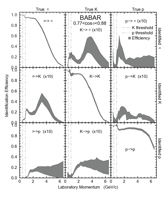
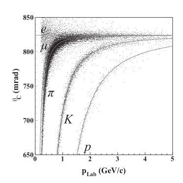
Similar to the BaBar technique [26], the hadron PID in the barrel will be analyzed using an event likelihood analysis with the DIRC and TPC information simultaneously. A measurement in the TPC gives very good hadron separation for very low momentum particles. But the ability of that technique to separate K- and p-K drops off quickly around 0.5 GeV and 0.8 GeV, respectively. Meanwhile, the pions and kaons exceed their respective DIRC Čerenkov thresholds in this momentum region, as shown in Figure 3.6. Therefore, the DIRC sensitivity for K- and p-K turns on sharply. A combined analysis of both pieces of information can give high PID purity up to a few GeV, as shown by the BaBar experiment [26]. At higher momenta, the DIRC ring resolution limits the separation capability. As shown in Figure 3.13, the K- and p-K separation gradually drops below plateau above momentum of 2 and 5 GeV, respectively. A pion and kaon efficiency can still be maintained at 5 GeV. The vast majority of hadron kinematics in SIDIS can be covered in the GeV collisions. In the GeV collisions, the low to intermediate- region in SIDIS are still well covered by this design.
3.6 Beamline detectors
Two detectors will be installed near the outgoing hadron beam, downstream of the ePHENIX detector. They will be included in the eRHIC machine lattice design [3].
- Zero Degree Calorimeter:
-
A Zero Degree Calorimeter (ZDC) is planned for the hadron-going direction for the ePHENIX IP. Consistent with the eRHIC IR design (Figure 3.14), the ZDC will be installed about 12 meters downstream of the IP centered on the hadron direction at the IP. A 5 mrad cone opening of the IP is guaranteed by the ePHENIX detector and beam line magnets. The ZDC for the current PHENIX experiment [31] and its design can be reused for this device.
- Roman Pots:
-
In exclusive deep inelastic scattering, the final state proton will have a small scattering angle and escape the main ePHENIX detector. Two silicon tracking stations (also called the Roman Pot spectrometer) will be installed close to the beam, inside the beam pipe, downstream in the hadron-going direction to capture such protons. Each of the ePHENIX Roman Pot stations utilizes four tracking modules to cover the full azimuthal angles. Each of the tracking modules can use the design of the existing STAR Roman Pots [32]. Depending on the eRHIC lattice and magnet design, their location will be around 20 meters from the IP. This Roman Pot spectrometer will provide high efficiency for the exclusive DIS events in the collisions.
Acknowledgments
We would like to acknowledge very helpful discussions and input from many groups, including the EIC tracking consortium, and BNL’s eRHIC Task Force, Collider-Accelerator Department, and Superconducting Magnet Division.
Bibliography
- [1] C. Aidala et al. sPHENIX: An Upgrade Concept from the PHENIX Collaboration. 2012. arXiv:1207.6378.
- [2] PHENIX Collaboration. The PHENIX Decadal Plan, 2010. URL: http://www.phenix.bnl.gov/phenix/WWW/docs/decadal/2010/phenix_decadal10%_full_refs.pdf.
- [3] A. Accardi et al. Electron Ion Collider: The Next QCD Frontier - Understanding the glue that binds us all. 2012. arXiv:1212.1701.
- [4] 2007 Long Range Plan: The Frontiers of Nuclear Science, 2007. URL: http://science.energy.gov/~/media/np/nsac/pdf/docs/NuclearScienceHighRe%s.pdf.
- [5] D. de Florian, R. Sassot, M. Stratmann, and W. Vogelsang. Extraction of Spin-Dependent Parton Densities and Their Uncertainties. Phys. Rev., D80:034030, 2009. arXiv:0904.3821, doi:10.1103/PhysRevD.80.034030.
- [6] M. Anselmino et al. Transversity and Collins functions from SIDIS and data. Phys. Rev., D75:054032, 2007. arXiv:hep-ph/0701006, doi:10.1103/PhysRevD.75.054032.
- [7] X.-D. Ji. Gauge invariant decomposition of nucleon spin and its spin - off. Phys. Rev. Lett., 78:610–613, 1997. arXiv:hep-ph/9603249, doi:10.1103/PhysRevLett.78.610.
- [8] A. Airapetian et al. Hadronization in semi-inclusive deep-inelastic scattering on nuclei. Nucl. Phys., B780:1–27, 2007. arXiv:0704.3270, doi:10.1016/j.nuclphysb.2007.06.004.
- [9] D. Boer et al. Gluons and the quark sea at high energies: Distributions, polarization, tomography. 2011. arXiv:1108.1713.
- [10] A. Daniel et al. Measurement of the nuclear multiplicity ratio for hadronization at CLAS. Phys. Lett., B706:26–31, 2011. arXiv:1111.2573, doi:10.1016/j.physletb.2011.10.071.
- [11] E. Iancu, K. Itakura, and L. McLerran. Geometric scaling above the saturation scale. Nucl. Phys., A708:327–352, 2002. arXiv:hep-ph/0203137, doi:10.1016/S0375-9474(02)01010-2.
- [12] eRHIC Task Force wiki. https://wiki.bnl.gov/eic/index.php/Main_Page.
- [13] F. Sauli. GEM: A new concept for electron amplification in gas detectors. Nucl. Instrum. Meth., A386:531–534, 1997. doi:10.1016/S0168-9002(96)01172-2.
- [14] P. Abbon et al. The COMPASS experiment at CERN. Nucl. Instrum. Meth., A577:455–518, 2007. arXiv:hep-ex/0703049, doi:10.1016/j.nima.2007.03.026.
- [15] R. Bell et al. The BaBar superconducting coil: Design, construction and test. Nucl. Phys. Proc. Suppl., 78:559–564, 1999. doi:10.1016/S0920-5632(99)00603-9.
- [16] S. An et al. A 20-ps timing device: A Multigap Resistive Plate Chamber with 24 gas gaps. Nucl. Instrum. Meth., A594:39–43, 2008. doi:10.1016/j.nima.2008.06.013.
- [17] B. Adams et al. Measurements of the Gain, Time Resolution, and Spatial Resolution of a 20x20cm MCP-based Picosecond Photo-Detector. Proceedings of the Vienna Conference on Instrumentation, 2013. URL: http://psec.uchicago.edu/library/doclib/documents/222/sendit.
- [18] B. Yu et al. A gem based tpc for the legs experiment. In Nuclear Science Symposium Conference Record, 2005 IEEE, volume 2, pages 924–928, 2005. doi:10.1109/NSSMIC.2005.1596405.
- [19] L. Musa et al. Letter of intent for the upgrade of the alice experiment. Technical Report LHCC-I-022, CERN, 2012.
- [20] B. Ketzer. A Time Projection Chamber for High-Rate Experiments: Towards an Upgrade of the ALICE TPC. 2013. arXiv:1303.6694.
- [21] T. Abe et al. The International Large Detector: Letter of Intent. 2010. arXiv:1006.3396.
- [22] P. Schade and J. Kaminski. A large TPC prototype for a linear collider detector. Nucl. Instrum. Meth., A628:128–132, 2011. doi:10.1016/j.nima.2010.06.300.
- [23] C. Woody. Future Applications of GEM Detectors at BNL. Technical report, 2013. Talk on RD51 Collaboration Meeting.
- [24] D. Abbaneo et al. Technical Proposal A GEM Detector System for an Upgrade of the CMS Muon Endcaps. Technical report, 2012.
- [25] Technical Design Report for PANDA Electromagnetic Calorimeter (EMC). 2008. arXiv:0810.1216.
- [26] I. Adam et al. The DIRC particle identification system for the BaBar experiment. Nucl. Instrum. Meth., A538:281–357, 2005. doi:10.1016/j.nima.2004.08.129.
- [27] W. Anderson et al. Design, Construction, Operation and Performance of a Hadron Blind Detector for the PHENIX Experiment. Nucl. Instrum. Meth., A646:35–58, 2011. arXiv:1103.4277, doi:10.1016/j.nima.2011.04.015.
- [28] T. Iijima et al. A Novel type of proximity focusing RICH counter with multiple refractive index aerogel radiator. Nucl. Instrum. Meth., A548:383–390, 2005. arXiv:physics/0504220, doi:10.1016/j.nima.2005.05.030.
- [29] E. Grauges et al. SuperB Progress Reports – Detector. 2010. arXiv:1007.4241.
- [30] D. Trbojevic, 2013. Private communication.
- [31] C. Adler et al. The RHIC zero degree calorimeter. Nucl. Instrum. Meth., A470:488–499, 2001. arXiv:nucl-ex/0008005, doi:10.1016/S0168-9002(01)00627-1.
- [32] L. Adamczyk et al. Single Spin Asymmetry in Polarized Proton-Proton Elastic Scattering at GeV. Phys. Lett., B719:62–69, 2013. arXiv:1206.1928, doi:10.1016/j.physletb.2013.01.014.