Operation and performance of the CMS tracker
Abstract
The CMS silicon tracker consists of two tracking devices utilizing semiconductor technology: the inner pixel and the outer strip detectors. They operate in a high-occupancy and high-radiation environment presented by particle collisions in the LHC. The tracker detectors occupy the region around the center of CMS, where the LHC beams collide, between 4 cm and 110 cm in radius and up to 280 cm along the beam axis. The pixel detector consists of 66 million pixels, covering about 1 m2 total area. It is surrounded by the strip tracker with 10 million read-out channels covering about 200 m2 total area. The proceedings describe the operational experience collected during the first three years of LHC running. Results include operational challenges encountered during data taking that influence the active fraction and read-out efficiency of the detectors. Details are given about the performance of the tracker at high occupancy with respect to local observables such as signal to noise ratio and hit reconstruction efficiency. Studies of radiation effects are presented with respect to the evolution of sensor bias, read-out thresholds in the inner pixels, and leakage current.
keywords:
LHC; CMS; Silicon Tracker1 Introduction
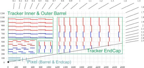
The CMS tracker is an all-silicon detector [1] with a sensitive area of over 200 m2. The sensors are arranged in concentric cylinders around the interaction region of the LHC beams and are situated in a 3.8 Tesla magnetic field. The purpose of the detector is to provide high precision measurement points in three dimensions along the curved trajectories of charged particles up to pseudorapidities . The best tracking efficiency is achieved in the barrel region, (figure 1). The charged particle tracks are used to reconstruct the positions of the primary interaction and secondary decay vertices. The tracker allows for rapid and precise measurements with temporal and spatial resolutions that fulfill the challenges posed by the high luminosity LHC collisions, which occur at a frequency of 40 MHz. The high particle fluence induces radiation damage, which also presents a challenge for the operation and data-reconstruction in the inner layers of the tracker.
The CMS tracker is comprised of two sub-detectors with independent cooling, powering, and read-out schemes. The inner sub-detector, the pixel detector, has a surface area of 1.1 m2. It is segmented into 66 million pixels of size 100 m by 150 m implanted into -type bulk with thickness of 285 m and -type back side. The detector has three layers in the barrel region at radii of 4.3 cm, 7.2 cm, and 11 cm, respectively, and two disks on each side of the barrel (the endcap regions) at 34.5 cm and 46.5 cm from the interaction point. The pixel detector contains 15840 read-out chips (ROC), each reading an array of 52 by 80 pixels. The ROCs are arranged into modules which transmit data via 1312 read-out links.
The sub-detector surrounding the pixels, the strip detector, is segmented into 9.6 million strips which are implanted into -type bulk with thickness of 320 m (500 m) in the inner (outer) layers or disks and -type back side. The pitch of the strips varies from 80 m to 205 m. The detector has 10 tracking layers in the barrel region that span radii from 25 cm to 110 cm and along the axis up to 120 cm: 4 layers in the inner barrel (TIB) and 6 in the outer barrel (TOB). It also has 12 disks in the endcap region with radii up to 110 cm and in up to 280 cm: 3 inner disks (TID) inside and 9 endcap disks (TEC) outside the TOB as shown in figure 1. Four layers in the barrel and multiple layers in the endcap regions of the strip detector are equipped with stereo modules allowing for 2D measurement. These modules have two silicon sensors mounted back-to-back with their strips aligned at a 100 mrad relative angle. Both sub-detectors are read out via a chain of analog electronic and optical links which are able to transmit absolute pulse height. In the pixel detector, the pixel coordinates are also transmitted. For the strips, all data-processing happens in off-detector electronics.
2 Operation of the tracker
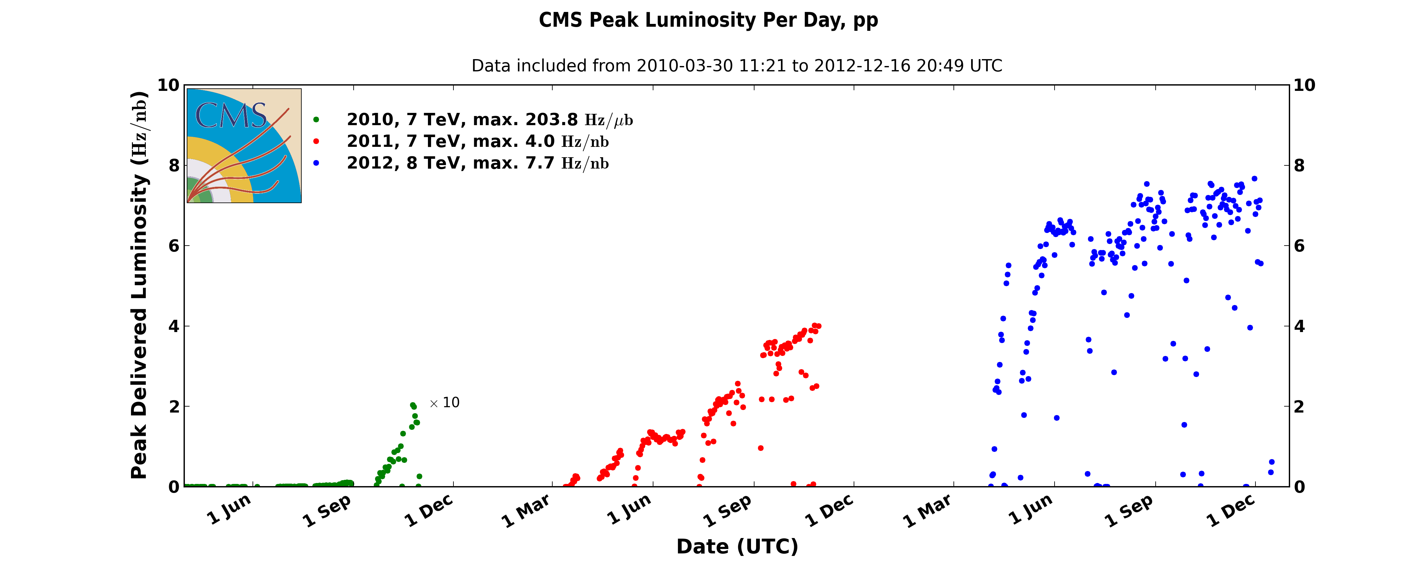
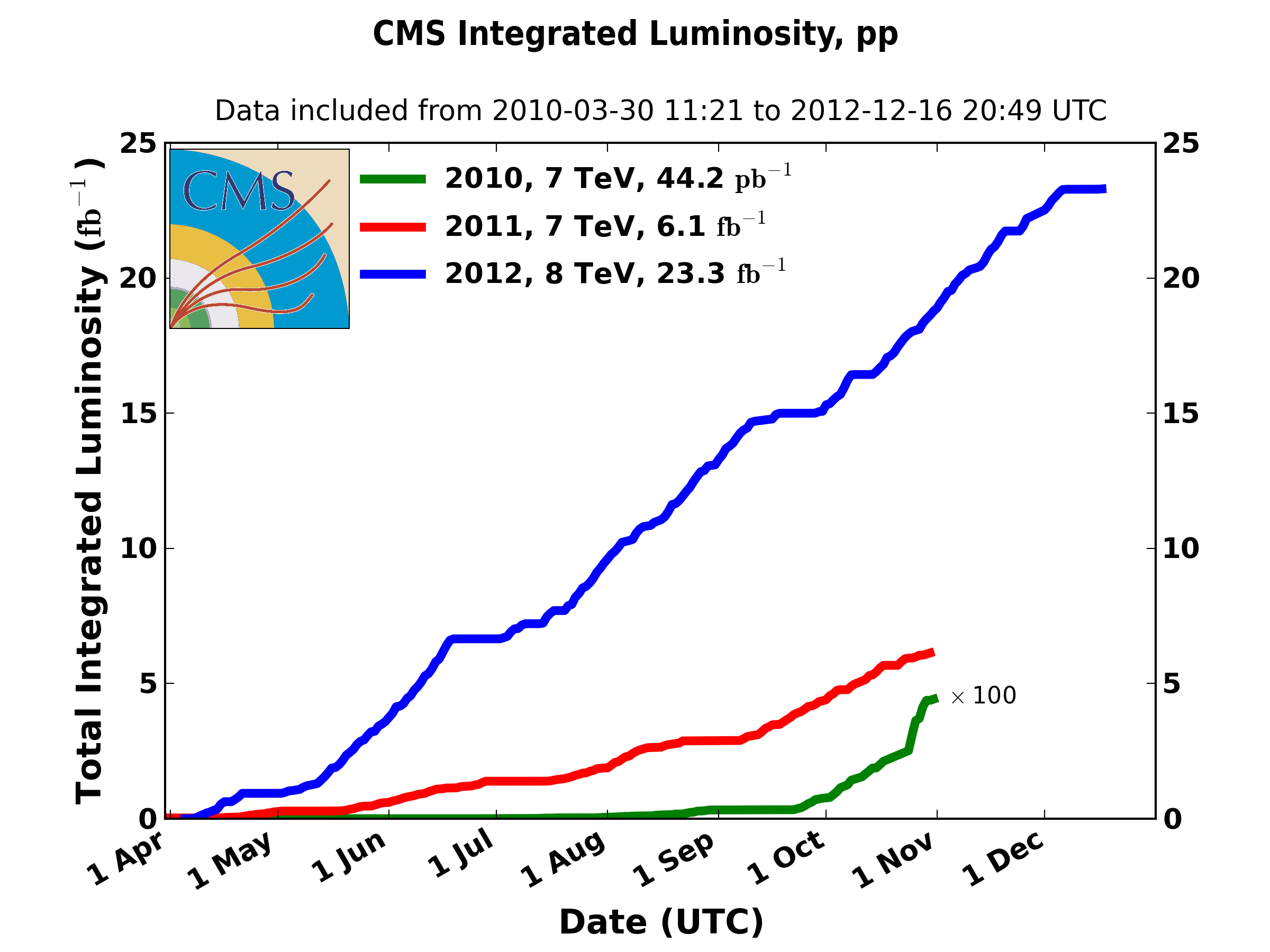
In the years of operation between 2010 and 2013, the LHC [2] has delivered about 6.1 fb-1 integrated luminosity of proton-proton collision data at 7 TeV and about 23.3 fb-1 at 8 TeV (figure 2). CMS has recorded overall 93% of these data [3]. The tracker was responsible for only about a third of the data lost, primarily because its high-voltage is ramped up only after stable collisions are declared. The reliability of the detector was constant over this period despite the increasing challenge presented by the continuously increasing instantaneous luminosity. The LHC reached its peak instantaneous luminosity of 7.71033cm-2s-1 in late 2012. High instantaneous luminosity causes multiple proton-proton interactions in the detector, known as pile-up. The average pile-up in 2012 was 21 simultaneous proton-proton collisions, and half of all events had pile-up between 21 and 40. The impact of pile-up will be further discussed later. By the time of the shutdown in 2013, about 2.3% of the barrel and 7.2% of the endcap modules of the pixel detector were inactive; mostly due to faulty wire-bonds or poor connections. Over the same period of data-taking, about 2.5% of the strip detector became inactive due to short-circuits in the control rings and HV lines, or as a result of faulty optical communications. Repair of the damaged modules was part of the maintenance performed during 2013; up to 1.5% of the pixel barrel, up to 0.5% of the pixel endcap, and up to 1% of the strip detectors were deemed recoverable.
3 Hit reconstruction
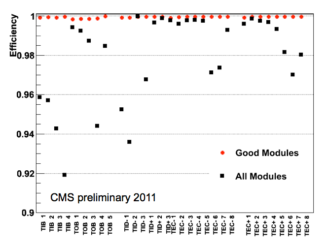
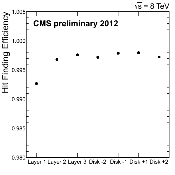
The first step in processing the data prior to track reconstruction is the efficient detection of hits, which represent the positions in the tracker’s sensors where charged particles passed through. Figure 3 shows the hit-finding efficiency in various layers of the strip and pixel detectors. After full track reconstruction, the efficiency is measured as the fraction of the number of particles that are expected to pass through the fiducial regions of the sensors in a given layer for which corresponding hits are found. In the case of the strip detector, a hit is considered to be found if it is on the same module in which the hit was expected to be observed. In the case of the pixel detector, a more stringent selection is required in order to address the higher particle occupancy: a hit must be found within a 500 m radius of the expected intersection point. In both cases, the only particle trajectories that are considered are those which have reconstructed hits on adjacent layers. The layer efficiencies exceed 99% in the strip detector and 99.5% in the pixel detector with the exception of the innermost layer of the pixels (see explanation in section 4.1).
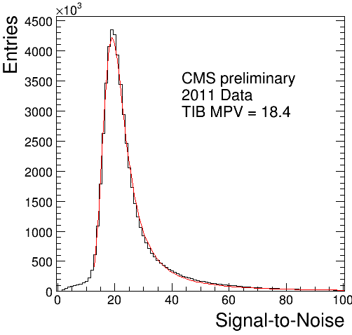
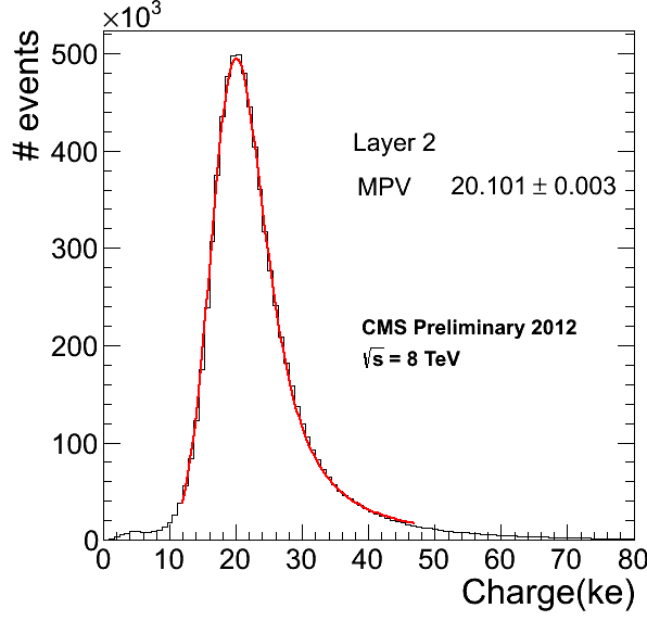
Besides the hit-finding efficiency, the resolution of the hit position is another important performance parameter of the tracker. They both rely on the complete measurement of clusters, contiguous groups of pixel or strip signals belonging to a hit, the formation of which depends on the path-length of the incident particles in the sensor and the Lorentz drift induced charge sharing. Figure 4 shows the signal-to-noise ratio in the strips and the cluster charge in the pixels for hits along reconstructed tracks. In both cases, the measurements are corrected for the impact angles of the incident particles, and the yields are fitted with a Landau distribution convoluted with a Gaussian.
4 LHC beam-induced effects
The data-taking conditions of the tracker detectors operating in the LHC environment are determined by two factors: the instantaneous luminosity through the resulting particle occupancy in a series of collision events, and the integrated luminosity which is closely correlated with the accumulated irradiation dose encountered by the sensors. The effects of the former are short-term and follow dynamically the changing beam conditions. The channel occupancy is defined as the number of pixel or strip measurements in an event divided by the number of all active pixels or strips. It scales linearly with pile-up. At the average pile-up of 9, which was typical in 2011, the pixel occupancy was 210-4 in layer 1 and 0.510-4 in layer 3 of the barrel pixel. The strip occupancy was 910-3 in the innermost layer of the TIB and 10-3 in the outermost layer of the TOB. The typical average pile-up increased by about a factor of 2.5 between 2011 and the end of 2012. Radiation-induced effects are cumulative in time and are essentially irreversible. The radiation dose acquired between 2010 and 2012 was estimated to be about 40 kGy in the innermost and 10 kGy in the outermost layers of the pixel detector. The strip detector integrated about 5 kGy radiation in the innermost layer of the TIB and 200 Gy in the outermost layer of the TOB. Both occupancy and radiation-induced effects are more important for the pixel detectors, as they are closer to the interaction region. In the following two subsections, studies performed on the pixel detector will be described.
4.1 Short-term, dynamic effects
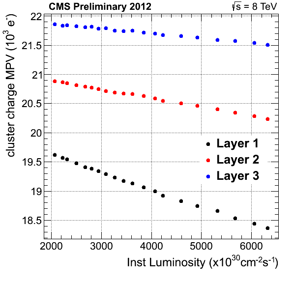
The power consumption of the ROCs increases in direct proportion to the particle occupancy in collision events, leading to higher operating temperatures. The temperature dependence of the pixel charge calibration is considered to be responsible for the decrease of the cluster charge at higher instantaneous luminosities, as shown in figure 5 (left), where the most probable value of the Landau-fit on the cluster charge is plotted.
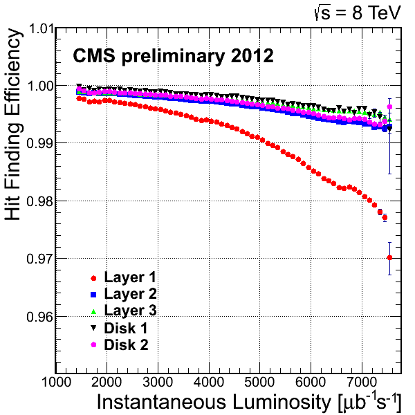
The CMS global trigger system needs about 4 s to make a decision and send a signal to the pixel detector in order to indicate whether a collision event is to be read-out or discarded. The ROCs store their hit information in internal buffers during this time. At high occupancy, the ROC buffers may entirely fill up with older hits, preventing the storage of hits in more recent events. Indirect evidence for the resulting loss of hit information can be seen in figure 5 (right). It shows the dependence of the hit finding efficiency on the instantaneous luminosity, which is the most pronounced for the innermost layer, as expected. Direct study of this mechanism is not possible, therefore approximate loss rates can only be inferred from simulation.
Another example of short-term beam effects on data taking is the so-called Single Event Upset (SEU). Particles from collisions may randomly flip bits in the control registers of the ROCs and auxiliary electronics. SEUs may interrupt or degrade data-taking. Their occurrence is proportional to the instantaneous luminosity and randomly distributed over time. A reprogramming of the ROCs solves this problem, which may be automatically triggered by the read-out front end, or the data quality monitoring framework.
4.2 Long-term, cumulative effects
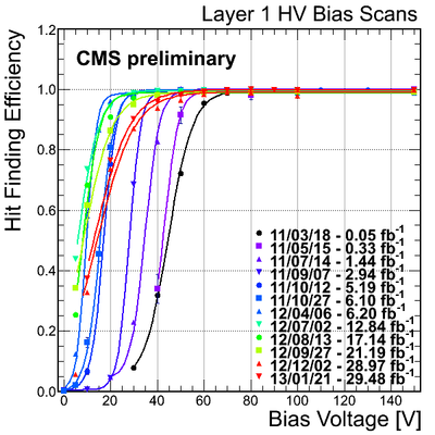
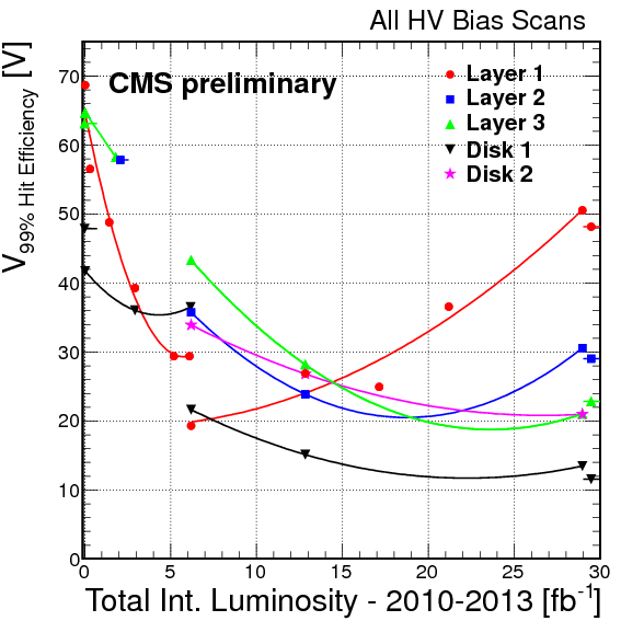
Radiation induced damage in the silicon bulk was monitored throughout the LHC running between 2010 and 2013. The bias voltage applied to the sensors during normal operation is 150 V in the barrel and 300 V in the endcap of the pixel detector. Special runs were performed regularly in which the bias voltage was increased in steps from zero to the operational voltages. The hit efficiency of the pixels was measured at each point, as shown in figure 6. The bias voltage that is needed to reach a depletion depth corresponding to full hit efficiency decreases with irradiation at first, then increases as expected due to changes in the effective doping [6]. The bias voltage at which the efficiency reaches 99% on each layer is plotted as a function of the integrated luminosity. It shows evidence of space charge sign inversion in the first and second layers.
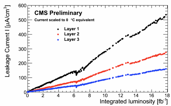
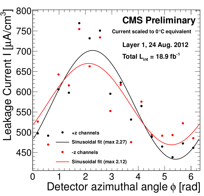
The leakage current in the pixels has also been constantly monitored (figure 7). Annealing took place during a longer shutdown after about 6 fb-1 and a shorter technical stop after about 13 fb-1 delivered integrated luminosity. The LHC collisions are not aligned in the center of the pixel detector leading to uneven irradiation of the modules along the azimuthal direction, as seen in the leakage current measurement in figure 7 (right).
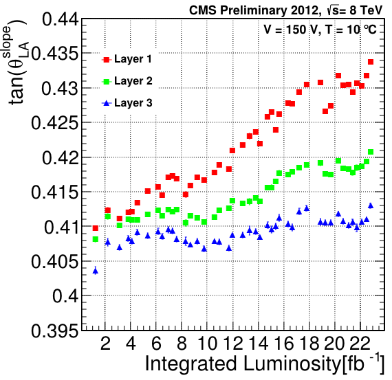
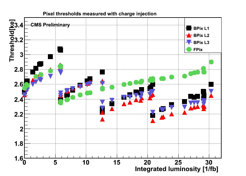
The Lorentz drift of the charges that are generated by high energy particles leads to charge sharing amongst adjacent pixels. The angle of the Lorentz drift near the mid-plane was measured repeatedly during 2012 and was found to be increasing with irradiation (figure 8 (left)). Charge sharing allows for better resolution as long as the pixels with small signals are nonetheless above read-out thresholds. These thresholds are measured in scans by injecting charges into individual pixels in incremental steps. The thresholds drifted higher with the accumulated irradiation and thus needed to be readjusted multiple times during the LHC running period (figure 8 (right)).
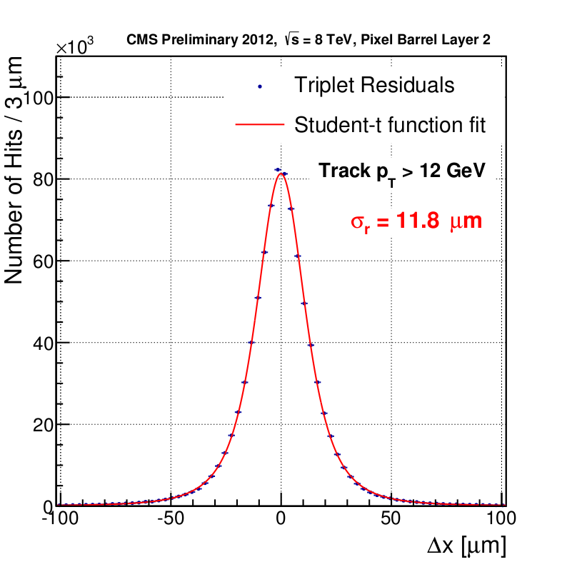
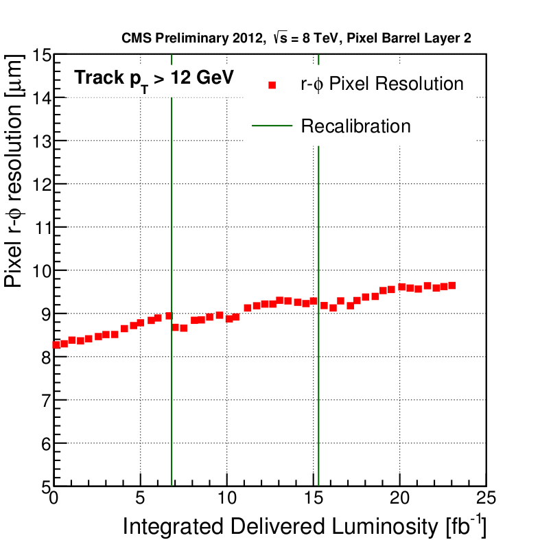
The resolution in the pixel detector is measured by re-fitting hit triplets with their associated tracks whilst omitting from the fit the hit on the layer under investigation, and by determining the distribution of the residuals between the expected and measured hit positions. The resolution is the width of the residual distribution after removing the errors which propagate from the fit of the other two hits. Figure 9 shows a residual distribution for hits in layer 2 and the evolution of the corresponding resolution as a function of delivered integrated luminosity. The resolution exhibits a slow degradation over time with two points of improvement corresponding to the times when the pixel read-out thresholds were recalibrated. The resolution also reflects our understanding of the constantly changing charge gain and Lorentz-angle calibrations.
5 Alignment of the tracker
The knowledge of each module’s position in three-dimensional space is required for track reconstruction when measurement points localised on individual modules are placed into the common frame of CMS. Movements and distortions of the tracker modules are periodically monitored using cosmic ray data and collision tracks by measuring the change in the distances between the expected trajectory impact points and reconstructed hit positions [7].
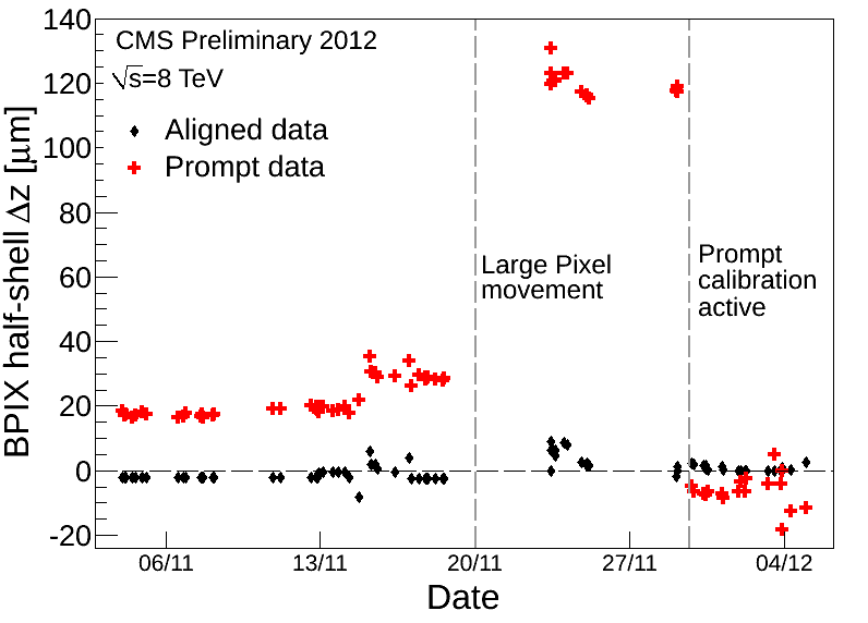
Pixel half-barrels are mechanically independent structures that may move with respect to each other in time, especially along the symmetry axis of the barrel. A relatively large movement with respect to the resolution was recorded on November 22, 2012 in connection with a cooling accident (see figure 10). This movement was detected in a subsequent calibration campaign. Since then, an automatic alignment procedure is performed within a few hours of the end of data-taking.
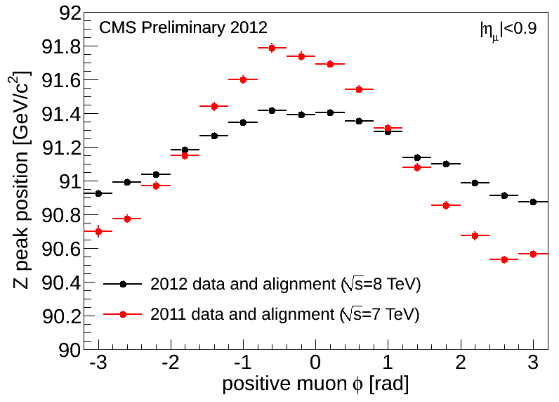
Distortions of the tracker geometry can lead to biases in the reconstructed track curvature. These biases are studied using the reconstructed invariant mass of the boson in decays as a function of the positive muon’s azimuthal angle (figure 10 (right)). The shape of the function implies a distortion of the tracker in the transverse plane, for example, the so-called sagitta. Note that figure 10 (right) does not represent the CMS muon reconstruction and calibration performance used in physics analyses, rather it is the raw tracker input to the event reconstruction.
6 Track and vertex reconstruction
The CMS tracking software was designed to operate in an environment with high particle occupancy respecting the limitations on CPU availability. It relies on an iterative procedure, each step of which produces a collection of fully reconstructed tracks. Earlier sequences search for tracks that are easier to find due to their higher transverse momentum, smaller impact parameter, and larger number of measured hits in all tracking layers. Hits associated to these tracks are then ignored in subsequent iterations which, in turn, search for tracks that fulfill less stringent requirements and therefore have higher combinatorial complexity, making them more difficult to find.
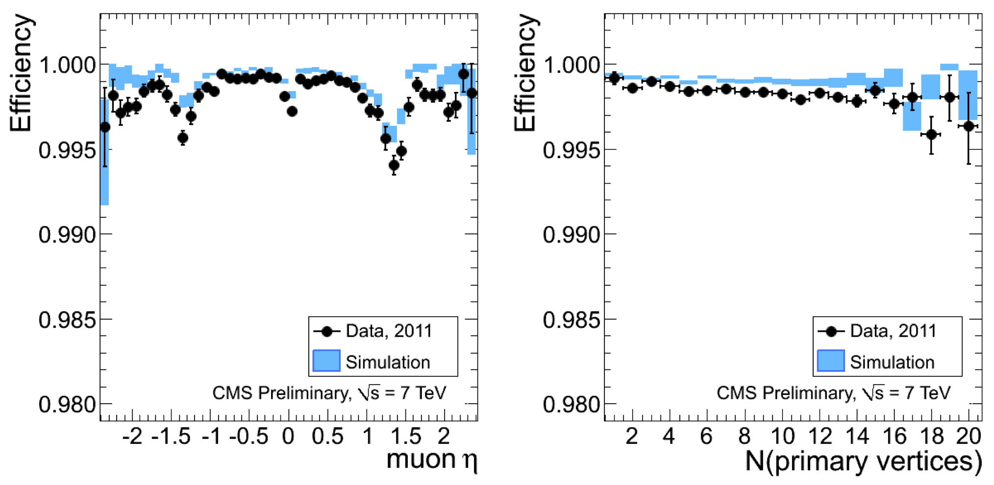
The track reconstruction efficiency was measured with the tag-and-probe method in events [8]. These events contain two muons, known as the tag and the probe, which have a combined invariant mass within a window around the nominal mass of the Z boson. The tag muons are well reconstructed using all information from the tracker and the muon systems. The probe muons are well identified in the muon system only. The tracking efficiency is then defined as the fraction of the probes which have matching tracks in the tracker. The tracking efficiency as a function of the pseudorapidity of the tracks and the number of vertices in the event are shown in figure 11.
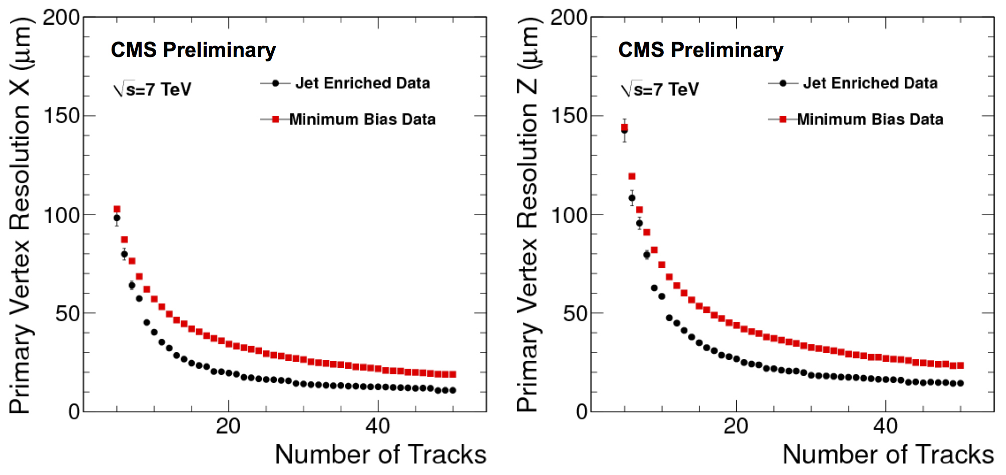
Each proton-proton interaction point in an event is considered a primary vertex. Its position is measured as the intersection of the associated tracks. It is located in three steps: first the tracks are identified, then they are grouped according to their vertex of origin, and finally the position of each vertex is fitted. The resolution of the vertex position is estimated by the split method [8] in which the group of tracks associated to a given vertex is divided into two sets. The distance between the vertex positions determined from both sets is then proportional to the resolution. The vertex resolution in the transverse plane and along the direction as a function of the number of fitted tracks are shown in figure 12.
The offline tracking and vertex finding algorithms are also used in the CMS high-level trigger (HLT) with configuration parameters customised for fast performance. The HLT processes a stream of events at rates up to 100 kHz, and attains output rates up to 400 Hz. Such a large reduction in event rate is achieved by utilizing track and vertex information in charged lepton and heavy flavour jet reconstruction in order to improve background rejection.
7 Conclusion
Run 1 of the LHC ended in February 2013. The CMS tracker has been operated successfully for over three years with excellent performance with regard to detector reliability and tracking. During this time, less than 3% of the detector became inactive and less than 5% of the delivered luminosity was lost due to the tracker. The track reconstruction methods were able to sustain high pile-up operation with excellent efficiency.
Before the restart of LHC operation in 2014 (Run 2), several improvements are expected to take place. Some parts of the detector will be replaced and broken modules recovered such that the fraction of inactive modules is expected to decrease below 1%. In order to compensate for the accumulated radiation damage, the coolant temperature will be lowered in both the pixel and strip detectors. Improved hit reconstruction will take into account the radiation induced changes in the sensors. Centering the pixel detector around the LHC beams will result in more uniform distribution of radiation damage along the azimuthal angle. In Run 2, both collision energy and instantaneous luminosity will nearly double. The tracking algorithms are going to be readjusted in order to meet the challenges presented by the higher occupancy.
References
- [1] S. Chatrchyan et al. [CMS Collaboration], The CMS experiment at the CERN LHC, \jinst32008S08004.
- [2] L. Evans and P. Bryant, LHC machine, \jinst32008S08001
- [3] CMS Luminosity - Public Results (2013), https://twiki.cern.ch/twiki/bin/view/CMSPublic/LumiPublicResults
- [4] CMS Tracker Detector Performance Results (2013), https://twiki.cern.ch/twiki/bin/view/CMSPublic/DPGResultsTRK.
- [5] V. Khachatryan et al., CMS tracking performance results from early LHC operation, Eur. Phys. J. C 70 (2010) 1165.
- [6] L. Rossi, P. Fischer, T. Rohe, N. Wermes, Pixel Detectors Springer-Verlag Berlin Heidelberg 2006
- [7] CMS Collaboration, 2012 CMS Tracker Alignment: Performance Plots, CERN-CMS-DP-2013-017
- [8] CMS Tracking Results (2012), https://twiki.cern.ch/twiki/bin/view/CMSPublic/PhysicsResultsTRK; CMS Collaboration, Tracking and Primary Vertex Results in First 7 TeV Collisions, CMS-PAS-TRK-10-005; CMS Collaboration, Measurement of Tracking Efficiency, CMS-PAS-TRK-10-002