Omega transmission lines with applications to effective medium models of metamaterials
Abstract
In this paper we introduce the concept of transmission lines with inherent bi-anisotropy and establish an analogy between these lines and volumetric bi-anisotropic materials. In particular, we find under what conditions a periodically loaded transmission line can be treated as an effective omega medium. Two example circuits are introduced and analyzed. The results have two-fold implications: opening a route to emulate electromagnetic properties of bi-anisotropic omega media using transmission-line meshes and understanding and improving effective medium models of composite materials with the use of effective circuit models of unit cells.
I. Introduction
Omega media, introduced in Refs. Saadoun, and proposed, , is a widely researched reciprocal special case of bi-anisotropic media. In bi-anisotropic media, electric field induces both electric and magnetic polarizations (and the same is true for magnetic field). The omega material is reciprocal and it is characterized by an antisymmetric magnetoelectric coupling dyadic. In case of the uniaxial omega media proposed the material relations can be written as
| (1) |
Here, and are electric and magnetic fields while and stand for electric and magnetic flux densities, respectively. Furthermore, is the omega coupling coefficient, and are, respectively, the vacuum permittivity and permeability, and the unit vector defines the only preferred direction in the uniaxial sample. The permittivity and permeability dyadics (denoted as and ) are symmetric and uniaxial.
Omega materials have an interesting property of having different wave impedances for opposite propagation directions. This implies asymmetry of reflection coefficients at interfaces with omega media when the illumination direction is reversed. Furthermore, the matching condition for interfaces between omega media and conventional magnetodielectric media depends on all three material parameters, opening interesting design possibilities in antenna and microwave engineering proposed ; Serdyukov . Most of recently introduced terahertz and optical metamaterial structures have the symmetry corresponding to the omega type of bi-anisotropic coupling (for example, arrays of complex-shaped metal particles or meshes positioned on one side of a dielectric substrate or similar multi-layer structures). Understanding and modeling of magnetoelectric omega coupling is a pre-requisite for understanding of effective response of these advanced electromagnetic materials and developing new applications.
It has been suggested that omega media can be realized by embedding electrically small resonant metal particles of an appropriate shape (e.g., -shaped metal inclusions, that is, centrally connected small dipole and loop antennas), into a conventional dielectric Saadoun . However, as such wire omega particles are resonant structures with all the polarizabilities (electric, magnetic, magneto-electric, and electro-magnetic) resonant always at the same frequency, the operational bandwidth, i.e., the bandwidth where is significantly different from zero, is rather narrow. This also means that the tunability of medium parameters in general is very limited and such media always have band-stop behavior. Losses in such media are typically also quite high when is significantly large. For these reasons, the possibilities for practical applications are limited. Here, we consider possibilities of realizing omega media with periodically loaded transmission lines (TLs). First, we compare the wave impedance of omega media with the Bloch impedance of a general periodically loaded TL and derive the required conditions for omega-like response. Second, a T-type circuit topology is considered to fulfill the required conditions. Third, a circuit topology using coupled inductors is analyzed. It should be emphasized that the goal, here, is not to replicate the narrow-band dispersion of any of the proposed realizations based on resonant particles, but rather to study more general media that still satisfy the material relations for omega media.
As will be shown below, the omega coupling parameter is defined by the asymmetry of unit cells of periodical structures (transmission lines in this example). This has important implications for problems of homogenization of composite materials (metamaterials) and electrically thin composite layers (metasurfaces). The unit cells (or periodically repeated planes of various inclusions) can be modeled by equivalent T- or -circuits, arranged in a periodical fashion. Here we will show that the asymmetry of these unit cells (most commonly imposed by the topology of the sample interfaces) can be properly accounted for by the effective omega-coupling parameter. This can remove the common problem of non-physical anti-resonance in effective permittivity and permeability, extracted from the reflection and transmission coefficients of planar slabs, without the need to introduce additional parameters which explicitly depend on the propagation constants of partial plane waves in the medium (as in Refs. alu1, ; alu2, ). From the physical point of view, the effective omega parameter accounts for first-order spatial dispersion effects in materials with non-negligible electrical size of the unit cells.
II. Omega media and omega transmission lines
A. Propagation constant and wave impedance
The propagation constant for axially propagating plane waves in omega media can be easily derived from (1) and is given by proposed ; Serdyukov
| (2) |
where is the free-space wave number, and are, respectively, the relative transverse permittivity and permeability, and is the normalized omega coefficient defined as . For lossless media with , is purely real. Therefore, for such media the propagation constant is real, i.e., there is wave propagation only when we have . An interesting property that separates omega media from conventional magnetodielectric media is that the wave impedance is different for waves traveling in the opposite directions. The wave impedance for the axial propagation can be written as proposed ; Serdyukov
| (3) |
where the two solutions correspond to opposite axial propagation directions.
B. Required conditions for unit cells
Our goal will be to emulate the wave-propagation properties of omega media with periodically loaded transmission lines. Bloch impedance can be considered as the characteristic impedance of periodically loaded transmission lines. It is defined simply as the ratio of the voltage and current at the terminals of the unit cell. It should be noted that the value of the Bloch impedance depends on how the terminal points are chosen and is, therefore, not unique for a given unit cell. The Bloch impedance for a general reciprocal periodic structure is defined using ABCD-parameters of unit cells as Pozar
| (4) |
Here, the two signs correspond to different propagation directions and the current is defined to flow always in the direction of the energy propagation. It should be noted that the top sign does not necessarily always lead to the correct solution for the positively traveling wave and the bottom sign for the negatively traveling wave, but the solutions may switch. Incorrect choice of sign leads to the non-physical result of negative real part of the Bloch impedance for passive structures. Taking this into account, the Bloch impedance for waves traveling along the positive () and negative () directions can be written as
| (5) |
Comparing the two impedances of (5) to the wave impedances of omega media (3) and assuming them to be equal, we can write the normalized omega coefficient in terms of the Bloch impedances and :
| (6) |
This can be further written using the ABCD parameters as
| (7) |
Therefore, as long as we have , i.e, the unit cell is asymmetric, and is finite, the normalized omega coefficient is non-zero. Furthermore, we can also determine the effective magnetodielectric wave impedance based on (3) and (5). This can be written as
| (8) |
Knowing the effective normalized omega coefficient and the effective wave impedance, we can also extract the effective refractive index by comparing the dispersion in omega media (2) and the dispersion in the periodically loaded TL. The latter can be calculated easily for any unit cell using basic ABCD-matrix theory and the Floquet theorem and is given by Pozar
| (9) |
where is the period of the structure. For reciprocal unit cells (), the two solutions are equal and (9) simplifies to
| (10) |
Knowing the effective normalized omega coefficient, the effective refractive index of the TL can be determined by comparing (10) to (2). Moreover, knowing the effective refractive index and wave impedance we can easily find the effective permittivity, permeability, and the (denormalized) omega coefficient.
C. T circuit
The simplest possible TL loading element is a T-type circuit (or alternatively -type), as we need an asymmetric circuit for the Bloch impedances for different propagation directions to be different. Let us take a look at a TL periodically loaded with T-type circuits as shown in Fig. 1. Let us also assume that the period of the unit cell is very small electrically. In this case, the ABCD-parameters, calculated by simply multiplying the ABCD matrices of each element in the unit cell in the right order, have the form
| (11) |
Therefore, the normalized omega coefficient, as defined in (7), can be written as
| (12) |
and the magnetodielectric wave impedance as
| (13) |
Again, we can see that for a symmetrical unit cell () we have .
Let us further simplify the analysis by assuming that we have , that is, the structure corresponds to the cascade shown in Fig. 2a. In this case, we have simply
| (14) |
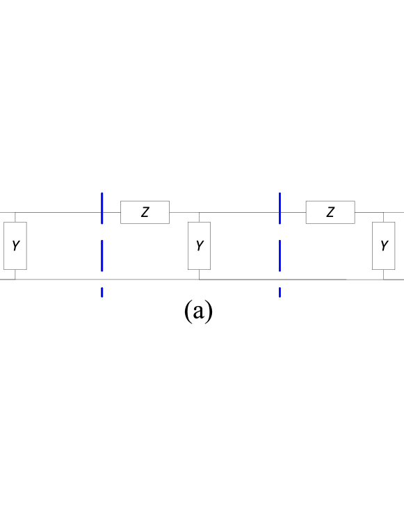
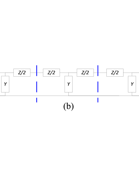
From (14), rather surprisingly, it can be seen that even a TL periodically loaded with a simple two-port consisting of a series inductor and a shunt capacitor can be interpreted as an omega media with and . Notably, if we would have chosen to be zero instead of , the magnetodielectric wave impedance would be the same but the normalized omega coefficient would have a different sign (). However, it is well known that the equivalent circuit of an infinitesimal section of an unloaded infinite TL can also be considered as a two-port consisting of a series inductor and a shunt capacitor. Therefore, loading a regular TL with these lumped elements is typically believed to just increase the equivalent permittivity and permeability with no need for any extra effective parameters. In fact, if we define the terminal points of the unit cell so that the unit cell is symmetric (i.e., series-shunt-series loading with the element values , , and as shown in Fig. 2b), we have and thus, according to (7), at all frequencies. As we consider here an infinite cascade, both unit cell choices illustrated in Fig. 2 are equally valid. Obviously, the dispersion in both cases is the same as the physical structure is the same (assuming that is electrically small). On the other hand, looking at (2) the different values of in these two cases indicate that the effective permittivity and permeability should be defined differently! In the former case, the stopband is interpreted to appear due to having whereas in the latter case it appears due to the term . Let us look at an example in order to clarify this confusion.
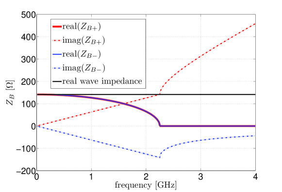
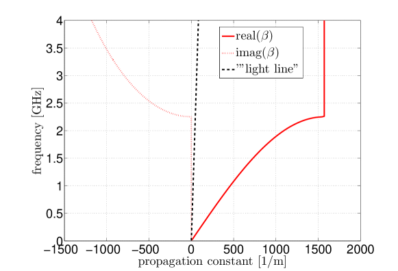
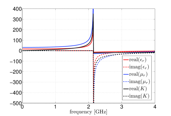
Let us first consider the asymmetric unit cell shown in Fig. 2a with and having the component values nH and pF. We also add some small losses in the series branch ( ). This is done just to avoid numerical problems in calculations and does not change the general conclusions. The period of the structure is 2 mm. The effect of the electrically short TL segments is neglected, as before. Let us first take a look at the Bloch impedance and dispersion in an infinite cascade of such unit cells shown in Figs. 3 and 4. As can be expected, the circuit has low-pass behavior. In the passband, the Bloch impedance is complex. The real part of the Bloch impedance is the same for both propagation directions while the imaginary part has the same magnitude but different signs. In the stopband, the real part of the Bloch impedance is zero for both propagation direction, but the imaginary part has different signs and magnitudes. Notably, the wave impedance term corresponding to in omega media (denoted with the black line in Fig. 3) is constant from 0 to 4 GHz. The normalized omega coefficient is shown in Fig. 5. As can be expected, as becomes larger than one, there is no propagation. Finally, in Fig. 6 the permittivity, permeability, and the omega coefficient are shown. In the passband, permittivity, permeability, and omega coefficient are real and positive and their values increase as we get closer to the stop band. They show resonant behavior in between the passband and the stopband and have negative values in the stopband.
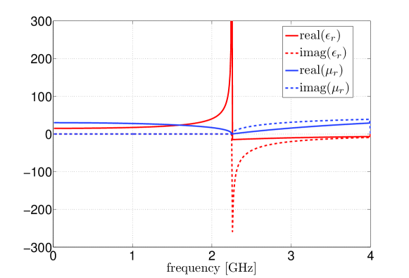
Now, let us look at the symmetric unit cell of Fig. 2b with and having the component values nH and pF. As before, the period is 2 mm and we have included some small losses in each series branch (2=0.0005). As the period is electrically small and the effect of the TL segments can therefore be neglected, this physically corresponds to the earlier case when an infinite cascade is considered. Obviously, this means that the dispersion is the same as before. The Bloch impedance, on the other hand, is the same for both propagation directions in this case. The Bloch impedance is equal to the magnetodielectric wave impedance of (13) and can be written as . Therefore, the Bloch impedance is constant with the value only if the product is sufficiently small. Clearly, if we consider a segment of a conventional, truly homogeneous TL with distributed series inductance and shunt capacitance, the term always approaches zero as the length of the segment approaches zero. Also, if we extract the material parameters, the permittivity and permeability are notably different than in the previous case, as can be observed from Fig. 7. Instead of both permittivity and permeability increasing in the passband, the permeability decreases. Typically, when we want to homogenize a periodical structure, we look at the lower passband where the permittivity and permeability are weakly dispersive. In this frequency range, the two solutions are approximately equal, as is much smaller than unity in the asymmetric case. In fact, the negative frequency derivative of the permeability is not a physical result for passive media as for passive low-loss media we must have and Landau . Also, the imaginary part of the permeability is positive in the stopband which also implies that the medium appears to be active. Therefore, this parameter extraction can only be valid at very low frequencies where the derivatives are approximately zero. This is not true for the parameter extraction in the previous asymmetric case, as in that case both derivatives are positive at all frequencies, and the anti-resonant artifact of one of the material parameters is removed. Notably, this only happens when the inductance of the other series inductor in the T-circuit is reduced to zero. Even if asymmetry (i.e., omega coupling) is introduced into the full T-circuit by making the inductance of one of the series inductors smaller than the inductance of the other one, the problem of non-physical permittivity and permeability remains as long as both inductors have non-zero values.
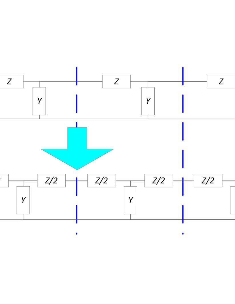
For an infinite structure, there is no physical reason to select one unit cell topology over the other. However, as soon as we consider finite-sized samples, we will see that the topologies of the first and last unit cells in fact define the symmetry or asymmetry of the unit cell and in this way also uniquely define the omega coupling coefficient. If the overall sample is formed by a set of complete unit cells, the effective parameter model with three effective parameters becomes unique. If at one of the interfaces the unit cell is incomplete, this can be accounted for by an addition of a series or parallel circuit element (equivalent to an additional surface current sheet in the effective medium model) or alternatively the sample can be interpreted as a set of complete unit cells terminated in an extra circuit element. Moreover, a set of complete asymmetric unit cells can be transformed into complete symmetric unit cells by adding a series element and a parallel element to one end of the cascade and a single series element to the other. This is illustrated in Fig. 8.

III. Omega parameter in effective medium models of metamaterials and metasurfaces
Periodically loaded transmission-line model or a periodical chain of connected two-port networks is one of the common approaches in modeling composite materials. Here, the electromagnetic properties of each period are modeled by the S- or Z-parameters of a two-port network, connected by short sections of transmission lines or directly. The main simplification in this model is that the adjacent layers of a multi-layer structure interact only by the single fundamental plane-wave harmonic, which is valid when the period along the propagation direction is larger than the period in the transverse plane.
For a spatially infinite periodical material a T- or -circuit can be equally adopted for any passive structure. If the structure topology is symmetric with respect to the propagation direction (the simplest example is a 3D periodical array of spherical inclusions), it is natural to adopt a symmetrical T- or -circuits as models of each unit cell. As we saw in the previous example, the extracted effective material parameters (permittivity and permeability) show non-physical behavior close to the resonant frequency of the unit cells. This is the well-known artifact of anti-resonant behavior of one of the two equivalent material parameters of composite materials containing resonant inclusions (metamaterials), see e.g. Refs. A1, ; A2, ; A4, ; A6, . The physical interpretations of this effect and approaches to developing better and more appropriate homogenization models have been widely discussed in the literature anti1 ; anti2 ; anti3 ; anti4 ; alu2 ; alu1 ; Hol ; Alitalo_anti . Following these studies, the main conclusions are that anti-resonances appear because we deal with composites containing resonant particles of a finite electrical size and the model of two equivalent parameters extracted from the plane-wave reflection and transmission coefficients for planar samples is not adequate (additional effective parameters are needed to account for spatial dispersion in the structure).
The results of the previous section clearly have important implications for the problem of composite material homogenization and defining physically meaningful effective permittivity and permeability. We have seen that the material parameters extracted from the symmetrical-unit-cell model exhibit the non-physical anti-resonant behavior while the parameters given by the asymmetrical-unit-cell model of the same actual structure show the physical Lorentz resonances, as is expected. From the point of view of extracted parameters, this means that one can get non-physical anti-resonant permeability and zero omega coupling coefficient (symmetric cells) or physical permittivity and permeability accompanied by positive or negative omega coupling coefficients. For the infinite periodical structure the definition of the unit cell is arbitrary: one can define a symmetric or different asymmetric cells at will. For an infinitely periodic structure, there is no physical reason to select one of these models. However, for a finite structure the topology of the unit cells at the boundaries defines the appropriate bulk effective material model. This is in line with the Ewald-Oseen extinction theorem (e.g., Ref. Born, ), which states that the incident field is compensated and the refracted wave is created by molecules (inclusions) located at the interface of a medium sample. Previously, it was suggested to introduce additional surface parameters (additional surface currents) on the interfaces of a composite slab to remove the anti-resonant artifact anti4 ; Hol ; Hol1 ; Hol2 , but in these models the bulk properties have been modeled by two parameters, without any bi-anisotropy. On the other hand, additional bi-anisotropy parameter has been introduced in Refs. alu2, ; alu1, ; Alu_new, , however, in that model the field-coupling terms explicitly depend on the propagation constants of partial plane waves in the sample, which makes the model difficult to use for samples of a finite thickness. Our present results give a simple and physically meaningful effective medium model where the first-order spatial dispersion effects due to electrically finite size of unit cells are accounted for by an additional omega coupling parameter. This model does not suffer from non-physical anti-resonant artifacts in extracted permittivity or permeability and correctly describes asymmetries in reflection from different sides of composite slabs. For extraction of all three effective parameters from reflection and transmission data, reflection should be measured from both sides of the sample slab. Finally we note that most of the known experimental samples of metasurfaces and metamaterials indeed have the topology corresponding to bi-anisotropic omega coupling (most commonly, samples are formed by dielectric substrate layers with various metal patterns printed on one side of the substrate). For such metamaterial layers proper introduction of the omega parameter removes the anti-resonant artifacts in the effective permittivity and permeability. Note that even if the individual inclusions in the bulk are not bi-anisotropic, the bi-anisotropy of the surface (the topology of the first layer of particles) defines bi-anisotropic response of the whole sample, seen as a bulk bi-anisotropy coefficient, as we saw in the above analysis of periodically loaded transmission lines.
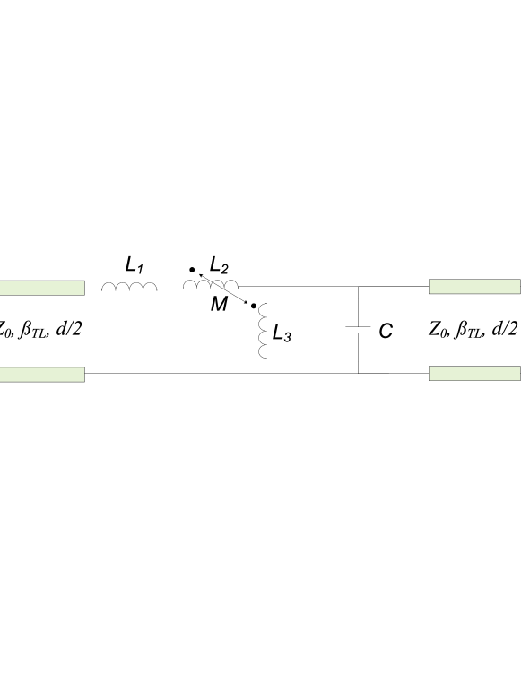
IV. Realization using unit cells with coupled inductors
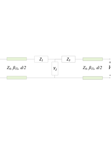
As discussed above, LC-loaded TLs have low-pass type of behavior with the normalized omega coefficient being zero at DC and increasing with the frequency. However, the permittivity and permeability appear to have different signs for the passband and the stopband as well as a strong resonance between the passband and the stopband. In omega media, the electric and magnetic responses are coupled. Following from this very basic fact, one might think of another kind of TL with omega-like response (Fig. 9). In this TL, the series and shunt branches (i.e., the magnetic and electric fields) are directly coupled via a mutual inductance. The circuit of Fig. 9 with the component values , , , and has been studied numerically as well as experimentally. Since the main goal of this study is to investigate the basic background physics of omega transmission line, the choice of operating frequency range is completely arbitrary. We have chosen a low RF range ( 30 MHz) in which the experiments can be performed easily because the parasitic capacitances are negligible. The period of the unit cell is 0.3 m and the characteristic impedance of the air-filled host line is 50 . The period of the unit cell is assumed to be equal to the total length of the two TL segments. Using the equivalent circuit for coupled inductors (e.g., Ref. Nilsson, ) and knowing the ABCD matrices for the basic circuit elements, the ABCD parameters can be easily determined and the circuit analyzed analytically. The manufactured unit cell prototype can be seen in Fig. 10. The number of windings around the same 12 mm plastic core for the inductors and was 18 and 4, respectively, and the diameter of the copper wire was 0.5 mm. The scattering matrix of coupled inductors was measured with Rohde Schwartz ZVA 8 Vector Network Analyzer (VNA). The extraction of the coupling coefficient from the measurement results gave 0.8. The inductor was also realized as a coil with 9 windings around a 12 mm plastic core. For the TL-segments, the 50 coaxial cable RG-58/U was used. As RG-58/U is polyethylene-filled ( = 2.26) instead of air-filled, the physical length of the cable sections in the measurement setup was 10 cm. The S-parameters of the assembled the unit cell were measured using the VNA and converted into ABCD parameters. These parameters were then used to calculate the Bloch impedances, dispersion in an infinite cascade of such unit cells as well as the equivalent material parameters.
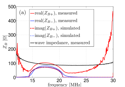
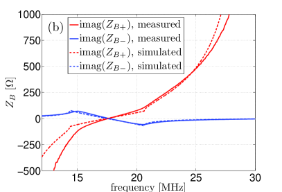
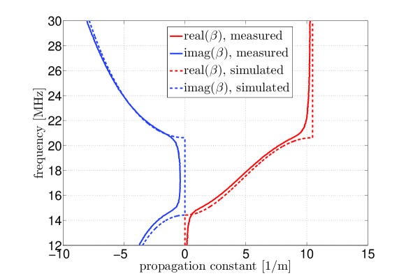
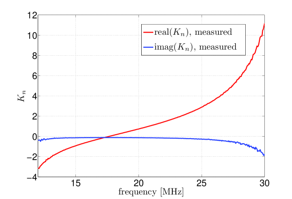
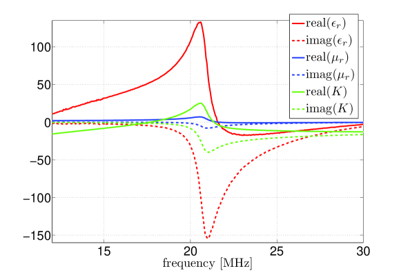
The Bloch impedance and the dispersion in an infinite cascade, in the frequency range 12 MHz – 30 MHz calculated both analytically and based on the measured S-parameters are shown in Fig. 11 and Fig. 12, respectively. Clearly, the TL has band-pass behavior. In the passband, the imaginary part of the Bloch impedance is different for different propagation directions except for the center of the passband where it is zero. Due to the intrinsic, asymmetric losses in the coupled inductors, the real part of the Bloch impedance is different for different propagation directions in the passband and has a non-zero value in the stopband. The agreement between the measurement results and the numerical results is in general quite good. The magnetodielectric wave impedance is also plotted in Fig. 11a. This can be seen to be fairly constant in the studied frequency range. The normalized omega coefficient extracted from the measurement results is shown in Fig. 13. In the studied frequency range, increases from 5 to 11 with the passband appearing when we have . Finally, the material parameters (permittivity, permeability, and the omega coefficient) extracted from the measurements are plotted in Fig. 14. Permittivity and permeability have similar behavior as in the earlier LC-loaded case, that is, they have a strong resonance between the passband and the stopband (or in this case the second stopband). However, such resonance does not appear between the first stopband and the passband. The permittivity is, here, notably larger than the permeability. The difference between permittivity and permeability could be decreased by increasing the size of the unit cell. The sign of the omega coupling coefficient changes in the middle of the passband (at 17.7 MHz) while permittivity and permeability are always positive in the studied example. However, by changing the element values appropriately epsilon-negative media (ENG) with omega coupling could also be realized. This gives us more freedom in choosing the material parameters compared to the LC-circuit loading where the permittivity and permeability have the same sign at all frequencies while omega coupling coefficient always has either the same sign (as in the studied example) or the opposite sign compared to permittivity and permeability depending on the order of the two elements within the unit cell. Still, effective permeability can only have positive values in this case due to the absence of capacitive series elements.

V. Comparison to omega wire media
The most common and the most studied way to realize a medium with omega coupling is to embed metallic wire inclusions having the shape of capital omega letter into a dielectric. The response of this so-called omega wire medium was studied numerically as well as experimentally in Ref. Kharina, . In omega wire medium, all the material parameters (permittivity, permeability and omega coefficient) are strongly resonant at the same frequency due to the resonant nature of the particle itself. The omega coefficient is non-zero only very near the resonance frequency of the particle (typically /2 length resonance) and elsewhere the particle is practically invisible to the incident field. Also, the losses near the resonance are considerable with the imaginary parts of permittivity, permeability and omega coupling coefficient being comparable to the corresponding real parts. This is in stark contrast to the presented TL implementations where the omega coupling coefficient is zero only at one frequency (DC for the LC loading circuit and an arbitrary frequency for the circuit utilizing coupled inductors). This is the frequency, where the unit cell appears symmetric. Furthermore, while the losses are large near the resonance also in this case, at frequencies farther from the resonance (where the omega coupling coefficient can still be considerable), the losses are small.
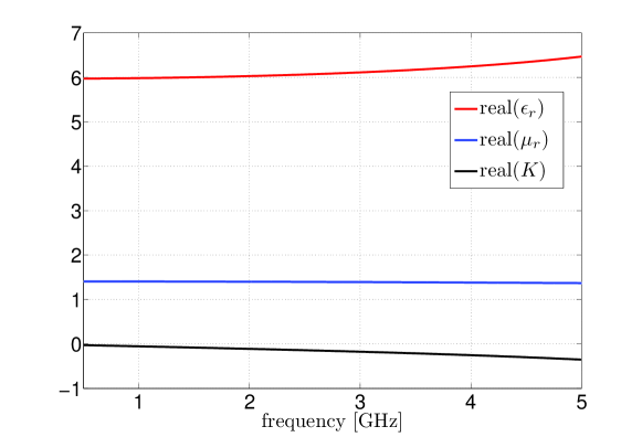
Though it was not the intention here to replicate the lossy narrow-bandwidth response of omega wire medium, we can easily realize the effective material parameters of wire omega medium at a single frequency. For example, the omega wire medium in Ref. Kharina, , consisting of thin wire -shaped inclusions resonant at 3.5 GHz embedded in epoxy with the resonance frequency of the medium being 3.2 GHz, has the effective material parameters , , and at 3.1 GHz as can be read from figures 3,4, and 5 of that paper. The losses are still fairly small at this frequency and are ignored here. The simplest way to realize this is to use T-circuit loading as shown in Fig. 1. The aforementioned material parameters can be replicated at 3.1 GHz by choosing, for example, the following values for the unit cell parameters: , with pF, with nH, , effective permittivity of the TL = 4.8, and = 7 mm. The calculated permittivity, permeability and omega coefficient for medium characterized by such unit cell are shown in Fig. 15. Clearly, at 3.1 GHz the material parameters have the same values as in the example of Ref. Kharina, . However, as can be expected, the dispersion is completely different. Now, there is very little dispersion in the material parameters compared to the omega wire medium since we are, in this case, operating far from any resonance. Obviously, such response at 3.1 GHz could also be replicated with the unit cell utilizing coupled inductors though the dispersion would again be different compared to both omega wire media and the T-circuit loaded TL implementation.
VI. Conclusion
We have discussed the connection between omega media and periodically loaded transmission lines. The effective omega material parameters for a general periodically loaded TL unit cell have been derived by comparing the characteristic impedances of omega media and a periodically loaded TL. Two examples of unit cells providing omega-like response have been analyzed. We have suggested to model periodical metamaterials with an equivalent omega medium or omega transmission lines. This model is free from the anti-resonance in one of the equivalent material parameters, which becomes possible because the first-order spatial dispersion effects are properly accounted for by the omega parameter, instead of being “embedded” into the conventional permittivity and permeability. It was shown that the equivalent omega parameter is determined by the topology of the unit cells at the boundary of composite-material samples. Finally, we have numerically and experimentally demonstrated unit cells of omega transmission lines and compared them to previously proposed realizations based on resonant particles.
Acknowledgments
Useful discussions with prof. C. Simovski are gratefully acknowledged. The authors thank Mr. D. Petricevic for help in manufacturing the prototype.
References
- (1) M.M.I. Saadoun and N. Engheta, Microwave and Opt. Tech. Lett. 5, (1992).
- (2) S.A. Tretyakov and A.A. Sochava, Electronics Letters 29, 12, (1993).
- (3) A. Serdyukov, I. Semchenko, S. Tretyakov, and A. Sihvola, Electromagnetics of Bi-anisotropic Materials (Gordon and Breach Science Publishers, Amsterdam, The Netherlands, 2001).
- (4) A. Alù, Phys. Rev. B 84, 075153 (2011).
- (5) A. Alù, Phys. Rev. B 83, 081102(R) (2011).
- (6) D.M. Pozar, Microwave Engineering, 3rd edition (John Wiley & Sons, USA, 2005).
- (7) L.D. Landau, E.M. Lifhutz, and L.P. Pitaevskii, Electrodynamics of Continuous Media, 2nd edition (Butterwoth Heinmann, 2002)
- (8) S. O’Brien and J. Pendry, J. Phys.: Condens. Matter 14, 4035 (2002).
- (9) V.V. Varadan and A.R. Tellakula, J. Appl. Phys. 100, 034910 (2006).
- (10) N. Liu, H. Guo, L. Fu, S. Kaiser, H. Schweizer, and H. Giessen, Nature Mater. 7, 31 (2008).
- (11) D. R. Smith, Phys. Rev. E 81, 036605 (2010).
- (12) T. Koschny, P. Markos, D.R. Smith, and C.M. Soukoulis, Phys. Rev. E 68, 065602(R) (2003).
- (13) T. Koschny, P. Markos, E.N. Economou, D.R. Smith, D.C. Vier, and C.M. Soukoulis, Phys. Rev. B 71, 245105 (2005).
- (14) C.R. Simovski and S.A. Tretyakov, Phys. Rev. B 75, 195111 (2007).
- (15) C.R. Simovski, Opt. Spectrosc. 107, 726 (2009).
- (16) A.P. Vinogradov, A.I. Ignatov, A.M. Merzlikin, S.A. Tretyakov, and C. R. Simovski, Opt. Express 19, 6699 (2011).
- (17) P. Alitalo, A.E. Culhaoglu, C.R. Simovski, and S.A. Tretyakov, J. of Applied Physics 113, 224903 (2013).
- (18) M. Born and E. Wolf, Principles of Optics: Electromagnetic Theory of Propagation, Interference, and Diffraction of Light, 7th ed. (Cambridge University Press, Cambridge, England, 1999).
- (19) S. Kim, E.F. Kuester, C.L. Holloway, A.D. Aaron, and J. Baker-Jarvis, IEEE Trans. Antennas Propag. 59, 2226 (2011).
- (20) S. Kim, E.F. Kuester, C.L. Holloway, A.D. Scher, and J.R. Baker-Jarvis, Progress In Electromagnetics Research B 36, 133 (2012).
- (21) X.X. Liu and A. Alù, Phys. Rev. B 87, 235136 (2013).
- (22) J.W. Nilsson and S. Riedel, Electric Circuits, 6th ed. (Prentice Hall, New Jersey, USA, 2000).
- (23) T.G. Kharina, S.A. Tretyakov, A.A. Sochava, C.R. Simovski, and S. Bolioli, Electromagnetics 18:4, 423–437 (1998).