Temperature Dependent Spin Transport Properties of Platinum Inferred From Spin Hall Magnetoresistance Measurements
Abstract
We study the temperature dependence of the spin Hall magnetoresistance (SMR) in yttrium iron garnet/platinum hybrid structures via magnetization orientation dependent magnetoresistance measurements. Our experiments show a decrease of the SMR magnitude with decreasing temperature. Using the sensitivity of the SMR to the spin transport properties of the normal metal, we interpret our data in terms of a decrease of the spin Hall angle in platinum from at room temperature to at , while the spin diffusion length and the spin mixing conductance of the ferrimagnetic insulator/normal metal interface remain almost constant.
In a metallic conductor with finite spin-orbit coupling, the flow of electric charge inevitably induces a spin current, and vice versa Dyakonov and Perel (1971); Hirsch (2004); Kato et al. (2004); Valenzuela and Tinkham (2006). In the literature, this is usually discussed in terms of the spin Hall effect (SHE), which describes the spin current induced by a charge current, and the inverse spin Hall effect (ISHE), i.e., the
charge current arising from a spin current Saitoh et al. (2006). The SHE and ISHE are widely exploited for the generation and/or detection of spin currents in ferromagnet/normal metal (FM/NM)
hybrid structures Bauer (2011), e.g., in the spin Seebeck effectUchida et al. (2008, 2010a, 2010b); Jaworski et al. (2010); Weiler et al. (2012a) or in spin pumping experimentsCzeschka et al. (2011); Weiler et al. (2012b); Qiu et al. (2012); Tserkovnyak et al. (2002); Ando et al. (2009); Costache et al. (2008); Mosendz et al. (2010). For a quantitative interpretation of such experiments, a detailed knowledge about the spin transport properties of the respective samples viz. their constituent materials is of key importance. Since any quantitative analysis is complicated by the coexistence of electronic and magnonic spin currents, hybrid devices based on ferromagnetic insulators (FMI) came into focus, and resulted in particular in a renewed interest in the ferrimagnetic insulator yttrium iron garnet (, YIG)Uchida et al. (2010a, b); Weiler et al. (2012a); Huang et al. (2012); Nakayama et al. (2013); Vlietstra et al. (2013); Althammer et al. (2013); Lu et al. (2013a); Isasa et al. (2013). The characteristic magnetoresistive effect reported from YIG/Pt (FMI/NM)
heterostructures by different groupsWeiler et al. (2012a); Huang et al. (2012); Nakayama et al. (2013); Vlietstra et al. (2013); Althammer et al. (2013); Lu et al. (2013b, a); Isasa et al. (2013), however, is controversially discussed. Huang et al.Huang et al. (2012) and Lu et al.Lu et al. (2013b, a) ascribe the observed magnetoresistance to a static magnetic proximity effect in Pt. On the other hand, the magnetoresistance in FMI/NM hybrids
can also be understood as a spin current-based effect, the so-called spin Hall magnetoresistance (SMR) Nakayama et al. (2013); Althammer et al. (2013); Chen et al. (2013). This interpretation naturally accounts for both the magnetization orientation dependence and the magnitude of the observed magnetoresistanceWeiler et al. (2012a); Nakayama et al. (2013); Althammer et al. (2013); Chen et al. (2013); Geprägs et al. (2012).
In this letter, we experimentally study the temperature-dependent evolution of the magnetoresistance in a set of YIG/Pt bilayer samples with different Pt thicknesses, and interpret our observations in terms of the SMR. We extract the magnitude of the SMR effect from magnetoresistance measurements as a function of the magnetization orientation (angle dependent magnetoresistance, ADMR). The ADMR data recorded in the temperature range consistently show that the SMR magnitude decreases with decreasing temperature. Using the SMR theory Chen et al. (2013), we extract the effective spin diffusion length in Pt, the real part of the spin mixing conductance of the YIG/Pt interface, as well as the spin Hall angle in Pt. We find that and are about independent of temperature, while decreases from at to at .
The SMR arises from the absorption () or reflection () of a spin current at the FMI/NM interface and thus depends on the orientation of the magnetization
of the FMI with respect to the spin polarization of the spin currentChen et al. (2013). This results in a characteristic dependence of the resistivity of the NM layer on the orientation of the magnetization in the adjacent FMI:Weiler et al. (2012a); Nakayama et al. (2013); Althammer et al. (2013); Vlietstra et al. (2013); Chen et al. (2013)
| (1) |
with the SMR amplitude
| (2) |
Here, is the intrinsic electric resistivity of the NM layer and is the magnitude of the magnetization-orientation dependent resistivity change arising from the interplay of charge and spin currents at the FMI/NM interface, is a unit vector orthogonal to both the direction of charge current flow and the film normal (see Fig. 1), and is the angle enclosed by and the magnetization orientation .
As evident from Eq. (2), the SMR varies characteristically with the thickness of NM Nakayama et al. (2013); Huang et al. (2012); Althammer et al. (2013); Vlietstra et al. (2013). Thus, the measurement of the SMR as a function of allows for a quantitative evaluation of both and of the NM. Since we here study Pt films with thicknesses down to , we explicitly take surface scattering effects into account by considering that the resistivity depends on the Pt film thicknessAlthammer et al. (2013).
The samples used in our experiments are YIG/Pt thin film heterostructures deposited onto (111)-oriented gadolinium gallium garnet (GGG) or yttrium aluminum garnet (YAG) single crystal substrates as described earlierGeprägs et al. (2012). The YIG thin films with a thickness of approximately were epitaxially grown via pulsed laser deposition from a stoichiometric polycrystalline target, utilizing a KrF excimer laser with a wavelength of at a repetition rate of .
The deposition was carried out in an oxygen atmosphere at a pressure of and a substrate temperature of (YAG) or (GGG), respectively.
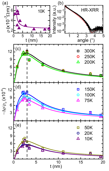
After cooling the sample to room temperature, we in-situ deposited a polycrystalline Pt layer of thickness via electron beam evaporation on top of the YIG film. We applied high-resolution X-ray reflectometry (HR-XRR) to determine for all samples, using the Software Package LEPTOS (Bruker AXS), (see Tab. 1).

We patterned the YIG/Pt bilayers into Hall bar structures (width , contact separation ) using optical lithography and argon ion beam milling (see Fig. 1(a)), and mounted them in the variable temperature inset of a superconducting magnet cryostat for magnetoresistance measurements (). We performed ADMR measurementsLimmer et al. (2006, 2008); Althammer et al. (2013) by rotating an external magnetic field of constant magnitude in the plane perpendicular to the current direction (oopj geometry) and recording the evolution of the sample’s resistivity . Here, denotes the angle between the magnetic field and the surface normal . The magnitude of the magnetic field is intentionally chosen much larger than the anisotropy and demagnetizing fields of YIG, in order to ensure that the YIG magnetization is always saturated and oriented along , .
By choosing the oopj rotation geometry, we can separate the SMR signal from an anisotropic magnetoresistance (AMR) in the polycrystalline Pt layer. In particular, one would not expect a magnetization orientation dependence of the resistivity in this configuration for AMR, as discussed in Lu et al. (2013a); Althammer et al. (2013)”.
The longitudinal resistivity of the sample can then straightforwardly be calculated from the voltage drop along the direction of charge current flow and the magnitude of the charge current density.
| substrate | substrate | ||||
|---|---|---|---|---|---|
| YAG | 0.8 | 0.7 | GGG | 3.5 | 0.7 |
| YAG | 2.0 | 0.8 | YAG | 6.5 | 0.9 |
| GGG | 2.2 | 0.7 | GGG | 11.1 | 0.6 |
| GGG | 2.5 | 0.5 | GGG | 17.2 | 0.6 |
| YAG | 3.0 | 0.8 | YAG | 19.5 | 1.0 |
Figure 1 shows a typical set of ADMR curves, recorded in the YIG/Pt sample with at different, constant temperatures while rotating a magnetic field . In a series of ADMR measurements at different magnetic fields (not shown here), we furthermore checked that does not depend on the field magnitude for . As evident from Fig. 1, the measured resistivity shows a -behavior with respect to the magnetization orientation, as also reported in earlier SMR experimentsAlthammer et al. (2013).
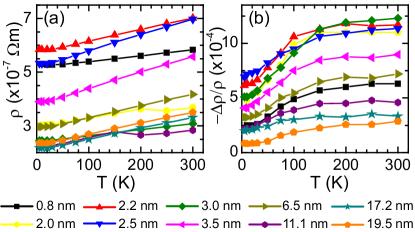
We now address of the normal metal Pt in more detail. We observe an increase of with decreasing , which we attribute to the finite roughness of the YIG/Pt interface. Upon decreasing the temperature from room temperature to , decreases by a factor of about [cf. Fig. 2(a)] for all samples as expected for metals. In order to take the film thickness and temperature dependence of into account, we use a thickness dependent resistivity Vlietstra et al. (2013); Castel et al. (2012) Fischer et al. (1980):
| (3) |
where is the resistivity for , the rms interface roughness, the mean free path for and the fraction of electrons scattered at the metal surface. Here we assume a diffusive limit () and choose (the thickest film studied is assumed to be bulk-like) and from a fit of Eq. (3) to the experimental data as exemplarily shown in Fig. 3(a) for the data. To enable a straightforward fit of the data as a function of the film thickness, i.e., across several samples, we use one and the same average rms value of for the interface roughness (derived from HR-XRR as listed in tab. 1) for all samples. As evident from Fig. 2(b), the magnitude of the SMR signal decreases with decreasing temperature for all samples. Upon plotting as a function of for different as shown in Fig. 3(c)-(e), a clear maximum in the SMR signal magnitude at around becomes evident. Note that according to Eq. (2) the SMR should show a maximum at . Fig. 3(c)-(e) reveals that this maximum appears at the same value of about for all temperatures within the accuracy of our measurements, suggesting that the spin diffusion length is only weakly temperature dependent.
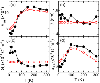
Finally, we use Eq. (2) to extract the Pt spin transport parameters from our set of experimental data. As discussed above, Eq. (2) depends on four parameters: , , and . Since we use calculated from Eq. (3), this leaves , , and as free parameters. Fitting the data then yields , and as given by the full symbols in Fig. 4. The parameters consistently describe our entire set of experimental data, as depicted by the solid lines in Fig. 3(c)-(e). As the temperature dependence of and is rather weak and comparable to the fitting error, we performed a second analysis with temperature independent and values [cf. Fig. 4(c)]. The values obtained from this simple analysis [cf. red open symbols in Fig. 4(a)] are very similar to the ones obtained from the full fit. This suggests that the real part of the spin mixing conductance is almost independent of temperature, as one might naively expect considering that the density of states in Pt does not significantly change with . The spin diffusion length obtained from our fit is comparable to earlier resultsUlrichs et al. (2013). However, since the spin diffusion strongly depends on the density and type of impurities in the NM, a significant difference of values for spreading from Ulrichs et al. (2013) to Kurt et al. (2002) is reported in the literature.
From the relation , we can calculate the temperature dependent spin Hall conductivity using the temperature dependent from the simulation and the measured electrical conductivity . Figure 4(d) shows exemplary for the sample [the -evolution is very similar in all samples studied, see Fig. 2(a)]. From both simulation approaches, we obtain a dependence that does not substantially change within the temperature range investigated, with a magnitude quantitatively consistent with other measurements Kimura et al. (2007).
In summary, we have investigated the SMR in YIG/Pt heterostructures with different Pt thicknesses via ADMR measurements at temperatures between and room temperature. We observe a decrease of the SMR at low temperatures for all Pt thicknesses. We used the SMR theory to extract the temperature dependence of the spin mixing conductance for the YIG/Pt interface, as well as the spin Hall angle and the spin diffusion length in Pt. Our data suggests and to be almost -independent, while decreases from at room temperature to at . Nevertheless, the spin Hall conductivity in Pt does not substantially change as a function of temperature, with .
We thank T. Brenninger for technical support, A. Erb for the fabrication of the stoichiometric YIG target and G.E.W. Bauer and M. Schreier for fruitful discussions. Financial support by the Deutsche Forschungsgemeinschaft via SPP 1538 (project no. GO 944/4) and the German Excellence Initiative via the ”Nanosystems Initiative Munich (NIM)” is gratefully acknowledged.
References
- Dyakonov and Perel (1971) M. I. Dyakonov and V. I. Perel, Physics Letters A 35, 459 (1971).
- Hirsch (2004) J. E. Hirsch, Physical Review B 71, 1 (2004).
- Kato et al. (2004) Y. K. Kato, R. C. Myers, A. C. Gossard, and D. D. Awschalom, Science 306, 1910 (2004).
- Valenzuela and Tinkham (2006) S. O. Valenzuela and M. Tinkham, Nature 442, 5 (2006).
- Saitoh et al. (2006) E. Saitoh, M. Ueda, H. Miyajima, and G. Tatara, Applied Physics Letters 88, 182509 (2006).
- Bauer (2011) G. E. W. Bauer, Solid State Communications 150, 459 (2011).
- Uchida et al. (2008) K. Uchida, S. Takahashi, K. Harii, J. Ieda, W. Koshibae, K. Ando, S. Maekawa, and E. Saitoh, Nature 455, 778 (2008).
- Uchida et al. (2010a) K. Uchida, H. Adachi, T. Ota, H. Nakayama, S. Maekawa, and E. Saitoh, Applied Physics Letters 97, 172505 (2010a).
- Uchida et al. (2010b) K. Uchida, J. Xiao, H. Adachi, J. Ohe, S. Takahashi, J. Ieda, T. Ota, Y. Kajiwara, H. Umezawa, H. Kawai, G. E. W. Bauer, S. Maekawa, and E. Saitoh, Nature Materials 9, 894 (2010b).
- Jaworski et al. (2010) C. M. Jaworski, J. Yang, S. Mack, D. D. Awschalom, J. P. Heremans, and R. C. Myers, Nature Materials 9, 898 (2010).
- Weiler et al. (2012a) M. Weiler, M. Althammer, F. D. Czeschka, H. Huebl, M. S. Wagner, M. Opel, I. Imort, G. Reiss, A. Thomas, R. Gross, and S. T. B. Goennenwein, Physical Review Letters 108, 106602 (2012a).
- Czeschka et al. (2011) F. D. Czeschka, L. Dreher, M. S. Brandt, M. Weiler, M. Althammer, I. Imort, G. Reiss, A. Thomas, W. Schoch, W. Limmer, H. Huebl, R. Gross, and S. T. B. Goennenwein, Physical Review Letters 107, 046601 (2011).
- Weiler et al. (2012b) M. Weiler, H. Huebl, F. S. Goerg, F. D. Czeschka, R. Gross, and S. T. B. Goennenwein, Physical Review Letters 108, 176601 (2012b).
- Qiu et al. (2012) Z. Qiu, Y. Kajiwara, K. Ando, Y. Fujikawa, K. Uchida, T. Tashiro, K. Harii, T. Yoshino, and E. Saitoh, Applied Physics Letters 100, 022402 (2012).
- Tserkovnyak et al. (2002) Y. Tserkovnyak, A. Brataas, and G. E. W. Bauer, Physical Review B 66, 10 (2002).
- Ando et al. (2009) K. Ando, J. Ieda, K. Sasage, S. Takahashi, S. Maekawa, and E. Saitoh, Applied Physics Letters 94, 262505 (2009).
- Costache et al. (2008) M. V. Costache, S. M. Watts, C. H. Van Der Wal, and B. J. Van Wees, Physical Review B 78, 9 (2008).
- Mosendz et al. (2010) O. Mosendz, V. Vlaminck, J. E. Pearson, F. Y. Fradin, G. E. W. Bauer, S. D. Bader, and A. Hoffmann, Physical Review B 82, 11 (2010).
- Huang et al. (2012) S. Y. Huang, X. Fan, D. Qu, Y. P. Chen, W. G. Wang, J. Wu, T. Y. Chen, J. Q. Xiao, and C. L. Chien, Physical Review Letters 109, 107204 (2012).
- Nakayama et al. (2013) H. Nakayama, M. Althammer, Y.-T. Chen, K. Uchida, Y. Kajiwara, D. Kikuchi, T. Ohtani, S. Geprägs, M. Opel, S. Takahashi, R. Gross, G. E. W. Bauer, S. T. B. Goennenwein, and E. Saitoh, Physical Review Letters 110, 206601 (2013).
- Vlietstra et al. (2013) N. Vlietstra, J. Shan, V. Castel, B. J. van Wees, and J. Ben Youssef, Physical Review B 87, 184421 (2013).
- Althammer et al. (2013) M. Althammer, S. Meyer, H. Nakayama, M. Schreier, S. Altmannshofer, M. Weiler, H. Huebl, S. Geprägs, M. Opel, R. Gross, D. Meier, C. Klewe, T. Kuschel, J.-M. Schmalhorst, G. Reiss, L. Shen, A. Gupta, Y.-T. Chen, G. E. W. Bauer, E. Saitoh, and S. T. B. Goennenwein, Physical Review B 87, 224401 (2013).
- Lu et al. (2013a) Y. M. Lu, J. W. Cai, S. Y. Huang, D. Qu, B. F. Miao, and C. L. Chien, Physical Review B 87, 220409 (2013a).
- Isasa et al. (2013) M. Isasa, A. Bedoya-Pinto, F. Golmar, F. Sanchez, L. Hueso, J. Fontcuberta, and F. Casanova, submitted (2013), arXiv:1307.1267.
- Lu et al. (2013b) Y. M. Lu, Y. Choi, C. M. Ortega, M. X. Cheng, J. W. Cai, S. Y. Huang, L. Sun, and C. L. Chien, Physical Review Letters 110 147207 (2013b).
- Chen et al. (2013) Y.-T. Chen, S. Takahashi, H. Nakayama, M. Althammer, S. T. B. Goennenwein, E. Saitoh, and G. E. W. Bauer, Physical Review B 87, 144411 (2013).
- Geprägs et al. (2012) S. Geprägs, S. Meyer, S. Altmannshofer, M. Opel, F. Wilhelm, A. Rogalev, R. Gross, and S. T. B. Goennenwein, Applied Physics Letters 101, 262407 (2012).
- Limmer et al. (2006) W. Limmer, M. Glunk, J. Daeubler, T. Hummel, W. Schoch, R. Sauer, C. Bihler, H. Huebl, M. S. Brandt, and S. T. B. Goennenwein, Physical Review B 74, 205205 (2006).
- Limmer et al. (2008) W. Limmer, J. Daeubler, L. Dreher, M. Glunk, W. Schoch, S. Schwaiger, and R. Sauer, Physical Review B 77, 205210 (2008).
- Castel et al. (2012) V. Castel, N. Vlietstra, J. B. Youssef, and B. J. van Wees, Applied Physics Letters 101, 132414 (2012).
- Fischer et al. (1980) G. Fischer, H. Hoffmann, and J. Vancea, Physical Review B 22, 6065 (1980).
- Kimura et al. (2007) T. Kimura, Y. Otani, T. Sato, S. Takahashi, and S. Maekawa, Physical Review Letters 98, 156601 (2007).
- Ulrichs et al. (2013) H. Ulrichs,V. E. Demidov,S. O.. Demokritov,W. L. Lim, J. Melander, N. Ebrahim-Zadeh, and S. Urazin, Applied Physics Letters 102, 132402 (2013).
- Kurt et al. (2002) H. Kurt, R. Loloee, K. Eid, W. P. Pratt Jr., and J. Bass, Applied Physics Letters 81, 4787 (2002).