Slipping magnetic reconnection during an X-class solar flare observed by SDO/AIA
Abstract
We present SDO/AIA observations of an eruptive X-class flare of July 12, 2012, and compare its evolution with the predictions of a 3D numerical simulation. We focus on the dynamics of flare loops that are seen to undergo slipping reconnection during the flare. In the AIA 131Å observations, lower parts of 10 MK flare loops exhibit an apparent motion with velocities of several tens of km s-1 along the developing flare ribbons. In the early stages of the flare, flare ribbons consist of compact, localized bright transition-region emission from the footpoints of the flare loops. A DEM analysis shows that the flare loops have temperatures up to the formation of Fe XXIV. A series of very long, S-shaped loops erupt, leading to a CME observed by STEREO. The observed dynamics are compared with the evolution of magnetic structures in the “standard solar flare model in 3D”. This model matches the observations well, reproducing both the apparently slipping flare loops, S-shaped erupting loops, and the evolution of flare ribbons. All of these processes are explained via 3D reconnection mechanisms resulting from the expansion of a torus-unstable flux rope. The AIA observations and the numerical model are complemented by radio observations showing a noise storm in the metric range. Dm-drifting pulsation structures occurring during the eruption indicate plasmoid ejection and enhancement of reconnection rate. The bursty nature of radio emission shows that the slipping reconnection is still intermittent, although it is observed to persist for more than an hour.
Subject headings:
Sun: flares – Sun: X-Rays, gamma rays – Sun: UV radiation – Sun: Radio radiation – magnetic reconnection – Magnetohydrodynamics (MHD)1. Introduction
Solar flares are the most energetic manifestation of solar magnetic activity. They are characterized by a rapid increase in emission over a broad range of the electromagnetic spectrum, from X-rays and extreme-ultraviolet (EUV) to radio wavelengths (e.g., Kane, 1974; Fletcher et al., 2011; White et al., 2011). A typical flare encompasses a wealth of dynamical phenomena that are manifestations of the release of magnetic energy via the process of magnetic reconnection (Parker, 1957; Sweet, 1958; Priest & Forbes, 2000; Zweibel & Yamada, 2009). One of the most distinct signatures of these dynamical phenomena is that of the formation of flare loops, which emit strongly in X-rays and EUV (e.g., Fletcher et al., 2011), and the accompanied flare ribbons prominent in EUV and up to visible wavelengths (e.g., Warren & Warshall, 2001). Eruptive flares also exhibit large-scale restructuring of the magnetic field accompanied by coronal mass ejections (CMEs) that possibly result from the expulsion of coronal magnetic flux ropes (e.g., van Ballegooijen & Martens, 1989; Amari et al., 2000; Moore et al., 2001; Green & Kliem, 2009; Green et al., 2011; Patsourakos et al., 2013) and are an important driver of space weather.
Based on the observations of eruptive flares, various models have been developed to describe and interpret their main features. The standard 2D CSHKP model (Carmichael, 1964; Sturrock, 1966; Hirayama, 1974; Kopp & Pneuman, 1976), for example, describes the formation of flare loops and the flux rope (e.g., Dere et al., 1999; Cheng et al., 2013), from the reconnection of coronal magnetic field lines. Magnetic reconnection releases magnetic energy in the form of particle acceleration and thermal energy. Energetic particles guided along the magnetic field can impact the chromosphere (e.g., Reid et al., 2012), where they lead to the formation of flare ribbons (e.g., Schmieder et al., 1996). The chromosphere can also be heated by thermal conduction (Petkaki et al., 2012). Both processes lead to chromospheric evaporation (Neupert, 1968), which quickly fills the flare loops (e.g., Raftery et al., 2009; Milligan & Dennis, 2009; Brosius & Holman, 2010; Del Zanna et al., 2011b; Ning, 2011; Doschek et al., 2013; Brosius, 2013). The high density in the flare loops makes them a prominent emission structures. Flare ribbons are the footpoints of these loops, and their emission comes from compact transition region features (e.g., Graham et al., 2011; Young et al., 2013) and the underlying chromosphere.
While the CSHKP model provides a straightforward picture of eruptive flares, it fails at describing the intrinsically 3D features of solar flares. Examples of such features include e.g. motion of EUV or X-ray sources parallel to the flare ribbons (e.g. Inglis & Gilbert, 2013), or the evolution of the twist or shear of coronal loops, which is important for the dynamics of both flare loops and the flux rope (Aulanier et al., 2012). Other models, for example the tether cutting model (Moore et al., 1997; Fan, 2012) or torus-unstable flux rope models (Török et al., 2004; Aulanier et al., 2010) have been proposed to extend the standard model for eruptive flares to 3D. In particular, the 3D numerical simulation of a torus-unstable flux rope (Aulanier et al., 2012; Janvier et al., 2013) has helped to shed light on the underlying reconnection mechanism forming both flare loops and the flux rope. The absence of 3D null-points means that the reconnection takes place in Quasi-Separatrix Layers (QSLs), and in particular in the thinning high current density region underneath the expanding flux rope.
The QSLs (Priest & Démoulin, 1995; Démoulin et al., 1996, 1997) are locations where the mapping of the magnetic field lines exhibits strong gradients, but is not discontinuous. This means that there are no separatrices dividing the magnetic field into regions of different connectivities, as is the case with magnetic null-points. Rather, connectivity domains are bordered by regions where the connectivity is strongly changing, but is still continuous. The magnetic field distortion is analytically measured by calculating the norm of the field line mapping (Démoulin et al., 1996) or the squashing degree (Titov et al., 2002; Pariat & Démoulin, 2012). Because of the distortion of the magnetic field, high electric current density regions can form where the distortion is the strongest (e.g., Aulanier et al., 2005; Masson et al., 2009; Wilmot-Smith et al., 2009). This therefore results in magnetic reconnection as ideal MHD can break down (Parker, 1957; Sweet, 1958; Priest & Forbes, 2000).
In the case of QSLs, magnetic field lines passing through them can undergo successive reconnection that is seen as an apparent “flipping”, or “slipping” motion (Priest & Démoulin, 1995; Priest et al., 2003; Aulanier et al., 2006). The apparent slipping motion is a consequence of the local diffusion in the reconnection region, where the neighbouring field lines continually exchange connectivities (Aulanier et al., 2006). Because of the local rotation of the magnetic field vector within the coronal diffusion region, this process induces apparent field line velocities all along their length that can be different from the plasma velocity (Priest et al., 2003; Aulanier et al., 2006). Slipping reconnection is theoretically predicted in both eruptive and confined flares, as investigated in Masson et al. (2012). Janvier et al. (2013) showed that the speed of the apparent motion of the field lines can be directly linked to the norm and the reconnection rate. This study provided an important insight on reconnection mechanisms in 3D and the link with magnetic topology. Since the QSLs are more general than true null-points which require discontinuities, slipping reconnection is a more general mechanism of energy release not only during solar flares, but also in active regions (Aulanier et al., 2007).
At first, current sheets required for reconnection can be formed dynamically, both in 2D (e.g., Magara et al., 1996; Lin & Forbes, 2000; Bárta et al., 2011) and also in 3D (e.g., Antiochos et al., 1999; Lynch et al., 2008; Aulanier et al., 2010; Kliem et al., 2010; Aurass et al., 2011). Then, the current layer itself can be destabilized, leading to the formation of several plasmoids and null-points moving along the sheet (e.g., Loureiro et al., 2012). Merging and fragmentation of plasmoids then results in smaller current sheet systems that can be associated with fast reconnection regimes, providing the necessary energy release rate and acceleration of particles (Shibata & Tanuma, 2001; Karlický, 2004; Bárta et al., 2008; Uzdensky et al., 2010; Bárta et al., 2011; Karlický & Bárta, 2011; Karlický et al., 2012). These processes can be observed in X-rays as the formation, ejection and interaction of plasmoids (Ohyama & Shibata, 1998; Kołomański & Karlický, 2007; Milligan et al., 2010) and in the dm-radio range as drifting pulsation structures (DPS, Kliem et al., 2000; Karlický et al., 2002; Karlický, 2004; Karlický & Bárta, 2007; Karlický et al., 2010). Magnetic reconnection at high coronal altitudes can also manifest itself as a radio noise storm (Elgaroy, 1977; Del Zanna et al., 2011a).
Based on the above, the general expectation is that during eruptive flares, slipping motion of the field lines should manifest itself as an apparent slipping motion of flare loops, and plasmoid emission in the form of DPS should be observed at radio wavelengths as a consequence of both the flux rope eruption and the reconnection regime involving dynamics of the current layer. To the author’s knowledge, these processes have not previously both been reported in the same flare. Moreover, reports of the slipping reconnection itself are rare (Aulanier et al., 2007; Testa et al., 2013) and none are associated with flares.
In this paper, we report on the X1.4 flare of July 12, 2012 that manifests both the slipping reconnection and in later phase the fast reconnection with plasmoids (DPSs). AIA observations of the flare are described in Sect. 2. This section contains an overview of the events during the flare together with analysis of the apparent slipping motion of the flare loops. Individual contributions to flare EUV emission as observed by AIA are obtained from DEM analysis in Sect. 3. Section 4 presents the results of an earlier numerical simulation reproducing the expansion of an unstable asymmetric flux rope. With the simulated region having similar features as the observed active region 11520, the simulation is directly compared to observations. Evolution of the QSLs and the flux rope are also described along with the slipping reconnection process. In Sect. 5, we report on radio emission associated with the flare. A Summary and Conclusions are given in Sect. 6.


| Approx. Time [UT] | Event description | Location [Solar , ] | Notes |
|---|---|---|---|
| 14:48–15:15 UT | Brightening of loop systems in AR 11521 | Fig. 1, second row | |
| 15:00 UT | Flare start in AR 11520 (first flare loop) | , above F1 | Arrow 1 in Fig. 3 top left |
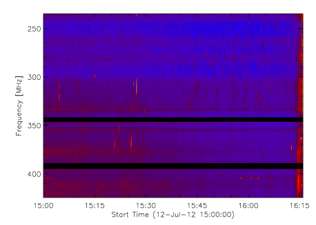
| 15:00 UT | Radio noise storm beginning at 200–500 MHz | Fig. 18, type III–like bursts | |
| 15:01–15:34 UT | Flare loops undergo slipping motion and gradual brightening | Sect. 2.2.1, Figs. 6–7 | |
| 15:07–16:10 UT | Growing system of hot loops in 131Å (erupts later) | Arrow 2 in Fig. 3 (rows 2–4) | |
| 15:43–16:07 UT | Second slipping event, gradual developing of NR | , NR | Sect. 2.2.2, Figs. 8–9 |
| 16:02–16:17 UT | Hot 131Å loop appearing at the end of NRH | Arrow 3 in Fig. 3 fourth row | |
| 16:05–16:25 UT | Brightening and development of the NRH | , NRH | Fig. 3 fifth row |
| 16:05–16:35 UT | Third slipping event along developing NRH | Sect. 2.2.3, Figs. 10–11 | |
| 16:13–16:33 UT | Large intensity enhancement along NR moving westward | , NR | Fig. 3 fifth row |
| 16:14–16:27 UT | PRH brightening, slipping assoc. with eruption in 131Å | , PRH | Fig. 3 fifth row, Figs. 12–13 |
| 16:16 UT | Start of a strong radio flare | Sect. 2.2, Figs. 18–18 | |
| 16:30–17:00 UT | PRH widens, with associated coronal dimming | Fig. 3 sixth row | |
| 16:34–16:40 UT | Deformation of the NRH | ||
| 16:40–17:00 UT | NRH extension in N-S direction, assoc. coronal dimming | Fig. 3 sixth row | |
| 16:49 UT | Peak of the GOES 1–8Å X-ray flux | Fig. 1 top |


2. SDO/AIA Observations and Data Analysis
An X1.4 flare occurred on 2012 July 12 in the large complex of active regions NOAA 11519, 11520 and 11521. It was an eruptive, long-duration event with a peak in the GOES 1–8Å flux at 16:49 UT (Fig. 1), but with flaring activity starting as early as 15:00 UT. The bulk of the flare EUV and X-ray emission (Sect. 2.1) occurred in AR 11520 (Hale class ), with one ribbon extending to AR 11521 (). The magnetogram for these active regions is shown in Fig. 1. The small, old AR 11519 () located further 100 westward was not involved in the flare. Altogether, the active region complex spanned nearly 40∘ in solar longitude.
2.1. Overview
The Atmospheric Imaging Assembly (AIA, Lemen et al., 2012; Boerner et al., 2012) on board the Solar Dynamics Observatory (SDO) consists of 4 identical, normal-incidence two-channel telescopes providing multiple, near-simultaneous full-Sun images with both high temporal resolution and high spatial resolution (1.5, pixel size 0.6). AIA images of the Sun are taken in 10 filters, 7 of which are centered on EUV wavelengths (94Å, 131Å, 171Å, 193Å, 211Å, 304Å, and 335Å), and 3 on UV or visible wavelengths (1600Å, 1700Å, and 4500Å). The EUV filters are centered on some of the strongest lines in the solar EUV spectrum. Such multi-filter AIA observations allow a study of the thermal structure of the solar atmosphere. However, the presence of a variety of emission lines originating at different temperatures within one filter bandpass makes the temperature responses of the AIA EUV filters (Fig. 2) highly multithermal in nature (e.g., O’Dwyer et al., 2010; Del Zanna et al., 2011c; Schmelz et al., 2013). This behaviour is also reflected in the responses of the 131Å and 94Å filters used for flare observations. Their responses are double-peaked due to sensitivity to both flare and coronal temperatures. The response of the AIA 131Å filter peaks at logK) = 5.75 and again at 7.05 due to contributions from Fe VIII and Fe XXI, respectively. The main contributors to the response of the 94Å filter are Fe X and Fe XVIII, producing peaks at logK) = 6.0 and 6.85, respectively. Fe XIV contributes to this filter as well (Del Zanna, 2013). Nevertheless, the flare emission observed by AIA is now well understood (Petkaki et al., 2012; Del Zanna, 2013). Together with its high temporal and spatial resolution, AIA is well-suited for studies of dynamical phenomena that occur on small scales, such as the evolution of individual features during a flare.
The flare evolution, as observed by SDO/AIA, is summarized in Fig. 3 and in Table 1, which should act as a reference guide for the online movies, as well as individual events during the flare discussed in this paper.
2.1.1 Pre-flare state, brightening in AR 11521 and the large-scale magnetic topology
The magnetic configuration of the AR 11520 before the flare is that of a forward S-shaped sigmoid visible only in AIA 94Å (Fig. 1, second row). This sigmoid overlies an active region filament F1 visible in AIA 304Å (Fig. 3, top right).
In the neighbouring AR 11521, a brightening of several loop systems occurs at around 14:48, i.e., shortly before the flare in AR 11520. One of the loop systems involved in the brightening is rooted in the vicinity of the position (arrow in Fig. 1). This position corresponds to the leftmost extension of the positive-polarity ribbon (PR) during the flare, and also to an intersection of one of the strongest QSLs with the photosphere (Fig. 1, bottom).
We obtained these QSL footpoints from a potential extrapolation of a SDO/HMI (Helioseismic Magnetic Imager, Scherrer et al., 2012) magnetogram using the method of Alissandrakis (1981) and Gary (1989). The potential extrapolation is an approximative method which assumes that there are no electric currents in the region. Clearly, this assumption is not valid either during the flare or near the vicinity of a sigmoid. Nevertheless, it can be used to infer the number and approximate shape of the large-scale QSLs that separate the magnetic flux closed within the active region complex from other closed, or locally “open” magnetic field lines (as also done in e.g., Chandra et al., 2009). We found that there are two strong, large-scale QSLs in the active region complex (Fig. 1, bottom): one semi-circular shaped on the left-hand side of the image in the negative polarities, and a second one at in the positive polarities. A portion of the QSL in the negative polarities is shifted to the north with respect to the footpoint locations of the sigmoidal loops. Such mismatch can be expected because of the electric currents present in the sigmoid.
As already noted, the positive-polarity QSL at corresponds well to the ribbon PR involved the flare (Fig. 3). This QSL provides the spatial connection between the flare in AR 11520 and the brightening in AR 11521 occuring immediately before the flare. We note that flaring, erupting or even radio events closely related in time have higher than a random occurrence (Wheatland, 2006), which could be a result of a “domino effect” (Chifor et al., 2006). Events related in time can have spatial connections through the magnetic field and its topology (e.g. Zuccarello et al., 2009; Liu et al., 2009; Jiang et al., 2011; Török et al., 2011; Shen et al., 2012; Mészárosová et al., 2013; Schrijver et al., 2013). Therefore, the brightening in AR 11521 is the earliest signature of the flaring activity in the entire AR complex.
2.1.2 Flare evolution
The flare itself starts at approximately 15:00 UT, when the first flare loop can be clearly identified in the AIA 131Å filter (Arrow 1 in Fig. 3). This is the first signature of high temperature flare emission in any of the AIA filters. At one end, the loop is rooted near in the QSL in the strongest positive-polarity spots in AR 11520. It then encircles the western spot counterclockwise from SW to NE and is rooted on the other end in the negative polarity. The loop is highly sheared and lies along the outer edge of the curved filament F1 (Fig. 3, top right). The 131Å flare loop is easily identifiable with one of the pre-existing sigmoidal loops.
Over the next 40 minutes, the flare gradually develops into a rather compact, highly sheared bundle of flare loops. Some of the flare loops undergo expansion in the SW direction (Arrow 2 in Fig. 3). Their footpoints gradually move along the QSL which develops into the positive-polarity ribbon (PR) and its hook (PRH, Fig. 3, second to fifth row). The apparent motion of the footpoints along the PR accelerates, and by around 16:25, the loops have erupted. This eruption is observed by the twin STEREO satellites as a CME (Fig. 4) consisting of expanding concentric coronal loops in 171Å. Unfortunately, the STEREO/EUVI instrument (Wuelser et al., 2004) does not contain “hot” flare filters, so the erupting loops cannot be directly identified in STEREO observations. The expansion of the 171Å loops can be driven by the erupting hot loops, as reported for another event by Zhang et al. (2012).
The arcade of flare loops meanwhile continues to widen, with the flare ribbons brightening and growing in lateral directions (Fig. 3, second to fifth row). These extensions and brightenings are often in the form of bright blobs in 304Å or 1600Å moving along the ribbons, associated with the apparent slippage of flare loops. This is discussed in detail in Sect. 2.2. Around 16:25 UT, the ribbons are the most prominent emitting structures in the 304Å observations (dominated by He II). Both ribbons exhibit hooks on their ends. These hooks are typically not as bright as the rest of the ribbon (Fig. 3, fifth row). The hooks show a quite rapid evolution with the eruption. For example, the hook of the negative-polarity ribbon (NRH) undergoes a deformation starting around 16:34 UT and subsequently extends by more than 100 in the N-S direction grazing along the large-scale QSL (shown in Fig. 1, bottom). The width of both the NRH and PRH increases over time to a maximum of about 20–30. Therefore, even if their width is increasing, they still stay rather narrow. Both of them also stay continuous and enclose narrow regions of coronal dimming observed in all AIA EUV filters.
This coronal dimming confirms that the erupting loops are rooted in both hooks. In fact, a bright loop arc located at the end of NRH can be identified around 16:02–16:17 UT (Arrow 3 in Fig. 3). This bright loop arc is a portion of a system of long loops with projected length of more than 250 (Fig. 5). These long loops are a part of the erupting structure. Because these loops are very long, for most of their length they are barely visible in the AIA 131Å observations due to low signal caused in turn by decreasing density along the loops. However, the motion of this loop system can be discerned in Fig. 5 or in the corresponding online Movie 3, where the running-difference of the 131Å observations with time lag of 1 min is shown. To guide the eye, the discernible portions of two long loops are outlined in Fig. 5, right by yellow and dark red lines. The running-difference also shows a series of other moving loops following the outlined ones. We emphasize that these long loops have general S-shaped appearance, and so are presumably non-potential. Unfortunately, due to the overlay of many emitting structures, the footpoints of these loops in the PRH cannot be traced with confidence.
One of the interesting features of this flare is that the filament F1, as well as other filaments within the AR complex (e.g. F2, Fig. 3, top right) do not erupt during the flare. Most importantly, F1 is still present and visible at 16:10–16:25 UT, i.e., the time of eruption of the hot loops. This suggests that F1 is constituted by a portion of the magnetic field not participating in the eruption and/or the flare. We note that the intensity of F1 as observed in the 304Å filter is highly variable with time, although there are little or no morphological changes. This is due to the fact that the He II emission originates from scattering (e.g., Andretta et al., 2003; Labrosse et al., 2010, and references therein). The scattering increases with the ribbon emission. An additional contribution comes from the diffraction pattern showing many secondary maxima (Poduval et al., 2013).
The GOES 1-8Å flux peaked at 16:49 UT, at which time the CME is in the interplanetary space and the arcade of flare loops is well developed and is cooling (Fig. 3 bottom).
2.2. Individual slipping events
We now focus on the apparent slipping motion of the flare loops observed in 131Å. This motion is observed throughout the early stage of the flare. Four times, when the apparent slipping motion is most prominent, can be identified. They are listed in Table 1 and discussed in the next subsections. Note that the plasma velocity can be decoupled from the velocity of the apparent motion of the field lines (Priest et al., 2003). Hereafter, we use the terms “apparent slipping motion” or “slipping motion” to describe the apparent motion of the flare loops as observed by AIA. The physical origin of the apparent slipping motion of flare loops is further discussed in Sect. 4.3.
2.2.1 15:00–15:34 UT
The first signature of apparent slipping motion of the flare loops is observed immediately at the start of the flare. The slipping is best visible in the negative-polarity footpoints of the first flare loops. Part of the time-sequence of this event is shown in Fig. 6 and in the online Movie 4. This figure is a zoom in the region NR indicated in Fig. 3. It shows AIA observations in filters 131Å, 94Å, 171Å, 304Å and 1600Å, with a time step of 5 min. The apparent slipping motions are best seen in 131Å and are weak in 94Å. All other filters show only concentrated enhancements of emission consisting of several point-like features. This means that this emission originates in the rather compact transition region near the loop photospheric footpoints (similarly as in Graham et al., 2011; Young et al., 2013). In other words, the loops emit primarily in Fe XXI and not in Fe VIII or Fe IX, meaning that their temperature is around 10 MK. We examine this point in detail in Sect. 3. We emphasize here that the transition region emission seen in all AIA filters is the first signature of the developing ribbon NR. During these early stages of the flare, the ribbon emission is only due to the footpoints of these dense, hot flare loops.
We note that some of the footpoints are very close to F1, especially around 15:05–15:10 UT. The F1 does not exhibit any significant structural changes, suggesting that its magnetic field is stable even to perturbations of the surrounding field as close as 1–2. Similarly, the sigmoid in 94Å remains largely unperturbed during this time (Fig. 6, Column 2), except for the widening of the arcade and apparent slippage of the flare loops.
To study the apparent slipping motion of the hot flare loops, we construct stackplots along artificial “cuts” inserted at = 315 and 320 (– plots). These cuts are shown in Fig. 6 as dark lines. The stackplots are shown in Fig. 7. Several intensity structures can be discerned, moving in the negative direction, in agreement with a visual inspection of the time-sequence in Fig. 6. One of the brightest structures is moving with an apparent velocity of 8.70.3 km s-1 (dotted line in Fig. 7). The error in velocity is estimated as the error of the line slope. There are other structures exhibiting apparent motion in the same direction, but they show large and intermittent intensity variations. There is no distinguishable velocity component in the perpendicular () direction.
The apparent slipping motion is also evident in the online Movies 1, 2 and 4, which have full temporal cadence (12 s). We note that the slipping motion can easily be missed in the visual inspection of AIA movies with lower cadence (e.g., 1 min).
2.2.2 15:43–16:07 UT
After the first time interval discussed in the previous section, the apparent slipping motion of the flare loops becomes less evident or nearly invisible. Then, a series of apparently slipping loops reappear shortly after 15:43 UT. These loops appear brighter and more dynamical than during the time interval described in Sect. 2.2.1. Figure 8 shows a portion of the time-sequence with a cadence of 1 minute. The slipping is again predominantly in the negative direction. The intensity variations of the apparently slipping loops make it difficult to distinguish individual structures moving in the opposite direction. We again construct stackplots along an artificial cut placed at = 320. The stackplots (Fig. 9) show a series of moving intensity features, with the one denoted by a long, dotted line having a velocity of 16.62 km s-1. The apparently moving loops are also clearly visible on the running-difference images (Fig. 9, bottom row) with a time delay of 12 s. At 15:52 UT, only one intense, apparently moving loop is visible, while at 15:57 UT, there are several, as shown by the stackplots. Note also that there are indications of somewhat weaker structures moving short distances in the opposite direction. The brightest one is outlined by the short dotted short line (Fig. 9), which corresponds to a velocity of 4.5 km s-1.
At 94Å, only the most intense of the 131Å loops can be clearly distinguished (Fig. 8). These can also be seen in the 94Å stackplot shown in Fig. 9 right. There are no discernible temporal shifts between the 131Å and 94Å bands, suggesting no temporally resolved cooling of the hot plasma.
The transition region emission near the footpoints of the apparently slipping loops is again visible in all AIA filters, with a clear one-to-one correspondence. The emission morphology is that of a chain of bright dots, resembling a pearl necklace in the AIA 304Å and 1600Å images at 15:57 UT. This transition region emission constitutes the elongating, developing NR.
2.2.3 16:05–16:35 UT
As the NR continues to develop, flare loops apparently move along it and along its hook (NRH). The most prominent example is shown in Fig. 10, with stackplots along the cut shown in Fig. 11. We denote the coordinate along the cut as , measured from left to right. The stackplots show multiple structures moving in both directions, but predominantly in the negative- direction. This is not surprising, since this is the local direction of the ribbon extension. The brightest apparently moving loops are seen at 131Å and 94Å. However, one of the loops is seen at 193Å and 131Å rather than at 94Å, apparently moving with a velocity of 445 km s-1 (Fig. 11, dotted line in the left panel). Considering the temperature responses (Fig. 2), this means that the loop emits in Fe XXIV. This occurence of a flare loop at 193Å is the only example we were able to find in this dataset. This is due to the fact that the 193Å channel is normally dominated by transition region and coronal emission from moss or warm coronal loops, with the secondary peak at logK) = 7.2 which is more than an order of magnitude lower than the primary one.
2.2.4 16:14–16:27 UT
The bulk of the brightest flare loops are rooted in a small portion of the PR oriented in the N-S direction, directly in the strongest positive-polarity sunspots. Since the magnetic field is strong here, the footpoints of the flare loops are concentrated and any apparent slippage here is not easily distinguished.
There is however one prominent event, exhibiting moving structures along the PR and its developing hook. This event is the eruption of a portion of the hot 131Å loops, associated with a travelling brightening along the PRH (Fig. 12). This brightening is seen in all AIA filters simultaneously. We note especially that this brightening happens immediately after the eruption of the long loop (Fig. 5) described in Sect. 2.1. We therefore interpret it as the apparently moving footpoints of the erupting loops.
We again construct a stackplot along the artificial cut inserted at = (black line in Fig. 12). The stackplot (Fig. 13, left) shows a single weak structure moving in the positive- direction with the velocity of 13615 km s-1 (dotted line). The vertical stripes of enhanced intensity are stationary, warm coronal loops. They are seen in the 171Å, both in Fig. 12 and on the 171Å stackplot (Fig. 13, right). Where the moving 131Å feature temporarily overlies these warm coronal loops, the intensity becomes enhanced, since the emission is optically thin.
The brightening of PRH due to the apparently moving footpoints of erupting loops causes intensity variations of the warm coronal loops anchored in the PRH. As can be seen from Figs. 12 and 13, these loops fade or disappear after the eruption.
3. DEM Analysis
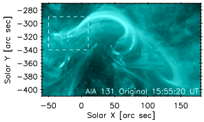
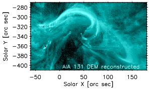
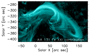
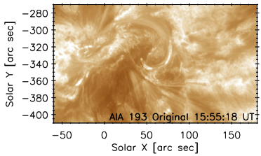
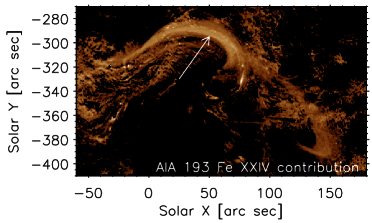
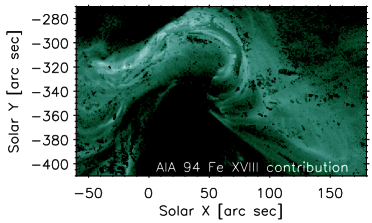
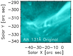
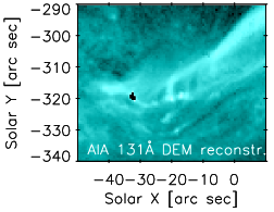
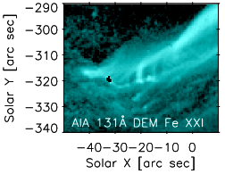
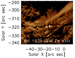
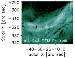
We now investigate the temperature structure of the individual structures within the flare, in particular the slipping and erupting loops. To do this, we performed a differential emission measure (DEM) analysis on each pixel of a selected AIA frame, within the field of view given by the = and = . We selected the observations at 15:55 UT as representative of the flare (c.f. Fig. 3, third row). At this time, both the slipping loops are visible (Sect. 2.2.2), together with the erupting loops moving along the PRH appearing as a single wide bundle (Arrow 2 in Fig. 3 third row, also Fig. 14 top left). We remind the reader that the presence of plasma at flare temperatures can already be discerned by visual inspection of the AIA images, in particular the 131Å and 171Å channels (Sect. 2.2.1). The aim of the DEM reconstruction is to estimate the contribution of the Fe XVIII 93.93Å, Fe XXI 128.75Å and Fe XXIV 192.02Å lines to the AIA flare bands 94Å, 131Å and 193Å, respectively. The contribution function of these lines peaks for log/K) = 6.85, 7.05 and 7.25, respectively. Therefore, these lines sample well the contribution of the hot plasma to the AIA observations.
We note that in general, the DEM inversion problem is ill-posed and under-constrained (e.g., Craig & Brown, 1976, 1986; Judge et al., 1997). Any solution found is not unique, as it typically contains additional constraints, such as some form of regularisation or smoothing of the solution, or an a-priori assumption on the functional form of the solution. (e.g., del Zanna, 1999; Aschwanden & Boerner, 2011; Hannah & Kontar, 2012). The regularized inversion of Hannah & Kontar (2012) has been specifically adapted for DEM reconstruction of the AIA data and used e.g. to recover DEMs at each AIA pixel in an observation of an eruptive off-limb event (Hannah & Kontar, 2013). We adopt this method for DEM analysis of the selected AIA images at 15:55 UT and use the implementation provided in the dn2dem_map_pos.pro IDL routine. In the reconstruction, the photospheric abundances of Asplund et al. (2009) are used similarly as in the flare modeling of Petkaki et al. (2012). Newest atomic data benchmarked against best available solar and laboratory spectra (see Del Zanna, 2013, Sect. 3 therein for details) are also used together with the atomic data from the CHIANTI database, v7.1 (Landi et al., 2013; Dere et al., 1997). We verified that the assumption of abundances and atomic data has only a small effect on the shape of the reconstructed DEMs. This is because the AIA responses are dominated by Fe ions (O’Dwyer et al., 2010; Del Zanna, 2013) and the atomic data for flare lines are reliable (Petkaki et al., 2012).
Once the DEM is recovered for each AIA pixel, predicted intensity maps for each AIA filter are calculated as follows. First, the DEM obtained for a given pixel is used to calculate a corresponding synthetic spectrum. To do this, CHIANTI v7.1 is used together with the newest atomic data available. The obtained synthetic spectrum is then multiplied by the spectral response of a given AIA filter, and finally integrated in the wavelength direction. Predicted contribution of a specific spectral line to a given AIA band is calculated in a similar manner. This is done for each pixel to obtain the predicted intensity map.
We determined that the AIA observations are best reproduced using 19 temperature bins of logK) = 5.5–7.3. This temperature interval is chosen to adequately cover the range of temperatures observed by the AIA instrument (Fig. 2) and the many contributions to its bandpasses (O’Dwyer et al., 2010; Del Zanna, 2013). The DEM reconstruction obtained for each AIA pixel results in good agreement between observed and predicted intensities for the 131Å, 171Å, 193Å, and 211Å filters. An example is shown in Fig. 14, top left and top center for the AIA 131Å. The 94Å and 335Å contain some areas, especially within the flare loops arcade, where the reconstructed intensities do not approximate the observed ones. At these locations, the DEM has large horizontal errors in the logK) = 6.6–6.8 temperature bins, affecting the Fe XVI and Fe XVIII contributions to the 335Å and 94Å bands, respectively. As an example, the predicted intensity map for Fe XVIII is shown in Fig. 14, middle row, right. The locations of poorly recovered DEMs correspond to dark spots and patches of darker areas, especially within the flare loops arcade. Note that these locations of poorly recovered DEMs at logK) = 6.6–6.8 correspond to locations where the LOS pierces the filament F1 and overlying flare loop arcade. The F1 shows dark as well as bright threads (e.g., Figs. 3 and 8; see also Alexander et al., 2013), while the overlying flare loops are visible in all of the AIA flare filters, namely 94Å, 131Å and 193Å (Fig. 14). We therefore suspect that the true DEM structure in such locations is complicated, with more than two peaks, and cannot be adequately recovered by the (Hannah & Kontar, 2012) method due to the enforced smoothness. Including more temperature bins at lower or higher log/K) improves the reconstruction only marginally. Nevertheless, outside of these areas, the DEM is recovered successfully, and the results confirm strong contribution of Fe XVIII to the AIA 94Å channel.
The results of the DEM reconstruction also confirm that the observed apparently slipping flare loops are indeed emitting strongly in Fe XXI (Fig. 14, bottom), which is the dominant contributor to the 131Å bandpass. In our case, Fe XXI contributes up to 50–85% of the observed flare emission in the 131Å channel. Weak Fe XXIV emission is also present in the 193Å bandpass (Fig. 14, middle row, center.) This Fe XXIV emission contributes of about 45% to the observed flare loops in the 193Å image (white arrow in Fig. 14). We note that these loops are weak in the 193Å image and can be discerned only outside of areas of strong moss emisson that dominate the observed 193Å morphology.
We note that there is some spurious contribution in the moss areas in the recovered Fe XXI and Fe XXIV intensities. However, this emission is typically 30 times weaker compared to the observed signal in the 193Å channel. The recovered DEM at these locations exhibit a weak secondary peak at logK) = 7.2 characterized again by large errors, and therefore uncertain.
In summary, the DEM reconstruction confirms that the slipping loops consist dominantly of flare plasma with temperatures up to logK) = 7.1–7.3.
4. Numerical simulation of a flux rope expansion and associated slipping reconnection
The mechanisms of solar flares and the associated formation of magnetic structures can be well reproduced with numerical models. In the following, we exploit the 3D MHD simulation performed earlier by Aulanier et al. (2012), recreating the evolution of a flux rope expansion during an eruptive flare. This simulation exhibits naturally occurring slipping magnetic reconnection as a result of the evolution of the model. This slipping reconnection builds both the flare loop arcade and the erupting flux rope (Aulanier et al., 2012; Janvier et al., 2013), which, as we will show in this section, compares well with the observations in qualitative terms. Although the simulation was not designed to fit any specific event, it is well suited for this particular flare (described in Sect. 2), as the photospheric magnetic field contains flux asymmetry, and geometrical comparison with the observations can be easily achieved by appropriate rotation of the simulation box.
4.1. Description of the numerical simulation
The initial conditions of the model are dynamically built so that the whole magnetic structure is torus-unstable. The details of the physical ingredients needed to build such conditions are described in Aulanier et al. (2010). The development of the torus instability leads to the upward expansion of the flux rope core, as well as the formation of a thin current layer where reconnection takes place. The reconnected field lines are of two types: they either further add to the envelope of the flux rope or they form the flare loops, as described in Aulanier et al. (2012) and Janvier et al. (2013). The numerical simulation is non-dimensionalized, and extends over a time period of , where represents the Alfvén time, i.e., the travel time for a distance at the Alfvén speed .
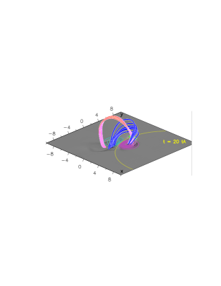
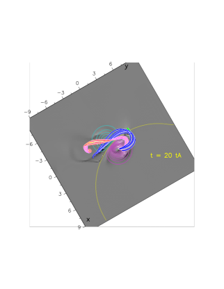
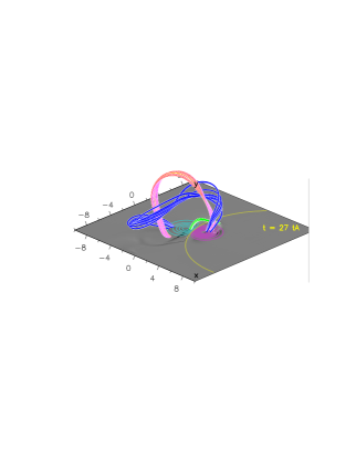
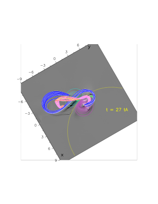
The region modelled in the present numerical simulation has similar features as that of the AR 11520 where the X1.4 flare was observed (Sect. 2). First, the asymmetry of the magnetic polarities is reproduced, with a 27% flux imbalance favouring the positive polarity in the photosphere. This asymmetry reflects the stronger, leading positive polarity and the weaker, trailing negative polarity of AR 11520 (Fig. 1). The numerical simulation also reproduces well the shape of the sigmoid as seen in the 94Å filter at the beginning of the flare (Fig. 1). This sigmoid, present at =15:00 UT, contains both -shaped pre-reconnected loops and -shaped post-reconnected loops as seen from the top, as is shown in the top right image of Fig. 17, where field lines are drawn at one time in the simulation.
Lack of null points and separatrices in the simulation implies that reconnection takes place in QSLs. Field lines then undergo a succession of reconnection processes as they cross the evolving QSLs, resulting in an apparent slipping motion. The details of such a mechanism have been thoroughly investigated in Janvier et al. (2013).

4.2. QSL structural evolution
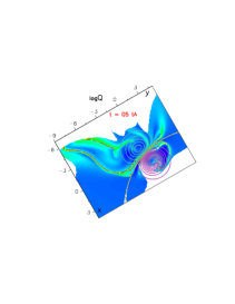
Quasi-separatrix layers, that correspond to a strong distortion of the magnetic field, are for the present simulation calculated with the TOPOTR routine (Démoulin et al., 1996) that integrates all the field lines of the volume from a fixed position in one polarity to its counterpart in the other polarity. TOPOTR then measures the squashing degree , that is a quantification of the magnetic field distortion (Pariat & Démoulin, 2012), and that defines QSLs for . 2D maps of QSLs can then be drawn anywhere in the volume, representing e.g. the QSL footpoints with a cut at the photosphere, or the hyperbolic flux tube (HFT) with a vertical cut into the volume which corresponds to the central part of the QSL volume.
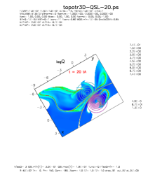
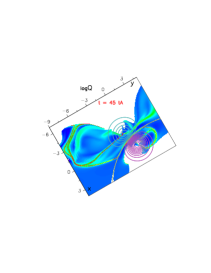
An example of these QSL footpoints at the photosphere () can be found in Fig. 15, where we have plotted the contour plot of log at three different times during the flux rope expansion of the present numerical simulation. The colour table indicates the strongest magnetic field gradients corresponding to log in red, and weaker gradients with log in blue. The regions in white correspond to areas where magnetic field lines are open, making the calculation of impossible (see also Janvier et al., 2013). The magnetic polarities in the photosphere are indicated by contour plots, with purple and cyan for the positive and negative polarities, respectively.
We note that since QSLs correspond to regions of high magnetic field distortion, they are expected to be formed near strong current density locations, as was demonstrated in Savcheva et al. (2012), Gekelman et al. (2012) and Janvier et al. (2013), although there is not necessarily a one-to-one correspondence (Wilmot-Smith et al., 2009). Then, the evolution of QSLs is very similar to that of flare ribbons, as is described in Sec.2 of Janvier et al. (2013).
At , two very thin QSL structures exist (Fig. 15, left, red color). Both are QSLs consisting of a straight part and a hook. Note that similarly to the magnetic polarity asymmetry, there is an asymmetry in the shape of those QSLs, most pronounced for the hooks. The QSL in the stronger positive polarity has a rounder hook, and is localized very near the center of the polarity. In contrast to this, the hook of the QSL in the weaker negative polarity extends toward negative values and is much broader, while the tip of the hook remains located near the centre of the polarity. The straight part of both QSLs is close to the polarity inversion line (PIL) indicated in yellow colour.
As time advances, two evolutions can be seen. First, the QSLs move away from each other, i.e., their straight parts move away from the PIL. This motion resembles the flare ribbon motion, as was suggested by Janvier et al. (2013) and as can be seen here by comparison with observations. Indeed, the distance between flare ribbons NR and PR in 304Å filter (Fig.3) increases over time, suggesting the separation of flare ribbons as is commonly observed during eruptive flare events.
Secondly, both QSL hooks become rounder with time. This is straightforward with the QSL in the negative polarity, as it extends toward negative -direction in the simulation (Fig. 15) and becomes rounder. The orientation of this extension corresponds to the east direction on the surface of the Sun, and is similar to the evolution of the NRH in AIA 304Å, (Fig.3, right) between 16:25 and 17:00 UT. However, the observed NRH does not become rounder, instead it elongates in the south direction and remains narrow, as was described in Sect. 2.1. This is because the large-scale magnetic configuration of the AR 11520 and 11521 is much more complex than in the simulation. The presence of surrounding magnetic fields on the Sun implies the existence of numerous large-scale QSLs that prevent the extension of the flare-associated QSLs (Chen et al., 2012). The broadening QSL is then squeezed by the surrounding structures, therefore explaining the unidirectional elongation in the observations instead of the isotropic broadening seen in the simulation.
In the simulation, the QSL hook in the positive polarity does not extend much and while it becomes rounder, it remains located near the center of the polarity. It is however difficult to compare the evolution of this QSL hook in the positive polarity with the observations. In Fig.3, the PRH is in fact an elongated ribbon, whose structure could be more complicated than in the simulation due to presence of other magnetic polarities, i.e., AR 11521.
For completeness, we note that at another QSL is present in the negative polarity in the simulation. Its straight part lies very close to the PIL, and the hook very close to the previously described QSL. This QSL is associated with a bald patch corresponding to field lines tangent to the surface. The bald patch does not play any role in the reconnection of field lines in the simulation. Its description will then be omitted in the further paragraphs.
The evolution of the QSLs is associated with the reconnection process leading to the formation of new pairs of reconnected field lines, including the flux rope envelope. This process is detailed in the following.
4.3. Slipping motion and associated kernel brightening
In the simulation, the upward expansion of the flux rope during its ejection creates a very thin current layer where reconnection occurs. This current layer is associated with a HFT, as described in Fig. 2 in Janvier et al. (2013). The field lines passing through the HFT undergo multiple reconnections, and this effect is seen as an apparent slippage of the field lines. In order to investigate this fast apparent motion in detail, the numerical data have been output from the simulation at a time cadence of less than one Alfvén time.
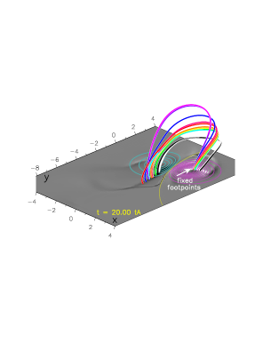
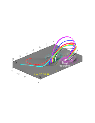
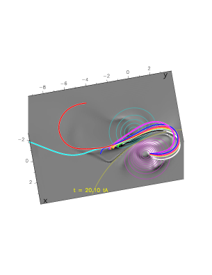
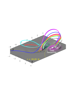
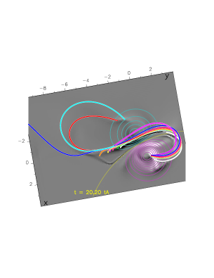
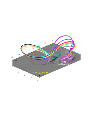
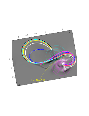
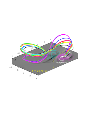
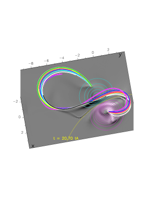
Figure 16 shows a set of selected field lines that are evolving from to . We picked these times since the magnetic field lines resemble the shape of the flare loops (Fig. 3). The photospheric surface at is shaded according to the photospheric current density , with the magnetic polarities indicated by pink and cyan contour plots. The field lines are integrated from their fixed footpoints anchored in the positive polarity close to the tip of the QSL hook. This hook is apparent in both the QSL trace (Fig.15, middle) and the structures. With advancing time, the connectivity of the field lines changes. For example, the blue field line is anchored in the negative polarity near the PIL at , while at it extends beyond the field of view of the simulation box, and at is connected to the tip of the hook of strong , similar in shape to the QSL hook in the negative polarity. This motion occurs similarly for the other field lines so that at , they are all connected in the negative polarity near the tip of the QSL or hook. The continuity of this motion can be seen in the online Movie 7.
This motion can in principle be observed with SDO/AIA imaging by two means. First, the loops themselves can be seen to be moving, as is the case for their NR footpoints discussed in Sects. 2.2.1–2.2.3 (also Figs. 6, 8, 10). Second, the field line footpoints can be seen to be moving as are the ribbon brightenings. These correspond to chromospheric or transition region emission due to the impact of energetic particles accelerated in the reconnection site. In practice, both are observed at the same time (Sect. 2.2).
We note that in the simulation, the fast motion of field lines is only an apparent motion due to the diffusion of magnetic field in the current layer, not necessarily associated with motion of plasma dragged by the moving field lines. This is because the time scale needed to fill the field lines by chromospheric evaporation is generally much larger than the time scale for multiple reconnections to take place in the current sheet. However, if reconnection were to happen on a time scale that is comparable with evaporation-field line filling, then the slipping motion of field lines could be identical with that of the flare loops. Note that the AIA instrument is able to observe only the portions of the field lines filled with high-density plasma at temperatures given by its temperature response (Fig. 2). Therefore, the coherent, apparently moving loops, reported in Sect. 2.2, do not neccessarily lie on a single, co-moving (slipping) magnetic field line. Rather, the apparent slipping motion of these loops is an illusion created by the apparent slipping motion of the magnetic field itself, coupled with the plasma thermal response.
We also note that the speed of the slipping motion along the QSL is not uniform. This can be inferred also from Fig.16. At and , field lines are only slightly moving in the straight part of the QSL, while their motion becomes much faster in the hook, as can be seen by comparing with . This slipping velocity profile has been investigated in detail in Sect. 3 of Janvier et al. (2013), where a peak in the velocity profile was found near the hook of the QSL. Smaller velocities were found at the beginning and at the end of the slipping motion, corresponding to the straight part of the -shape and tip part of the hook. The peak in the velocity profile can be explained by the fact that the reconnecting field lines are passing through the HFT, where is the highest, and the changes in magnetic connectivity the most drastic.
This change of slipping motion speed can also be seen in the observations (Sect. 2). As seen in Figs. 6, 8 and 10, one can see different sets of loops slipping at different times during the flare, yet their footpoints are mostly located in the straight part of the NR (Fig. 3). These slipping loops can be seen in this location because the field line slipping motion is slow, leaving enough time for filling the field lines via chromospheric evaporation. It is then possible to measure the velocity of this motion with stackplots along different cuts (Figs. 7, 9, and 11). Similarly, a bright loop appears at the tip of the NRH at 16:10:08 UT (Arrow 3 in Fig.3). This loop can be associated with a slipping set of field lines found at 15:55:08 UT.
Contrary to flare loops, kernel brightenings are much more visible moving along the ribbons, as can be seen in the NRH in the online Movie 2 and also in the Fig. 3 (right column). However, this kernel motion is not continuous but rather scattered, although the associated reconnection process should be continuous. This can be explained in terms of energy deposition along the QSL footpoints. The energy from the reconnection process is deposited at the chromosphere thanks to the energetic particles accelerated at the reconnection site. When the field lines are moving slowly, the energy is deposited in a small area of the QSL footpoint, so that the resulting chromospheric or EUV emission due to evaporation is large. In contrast, when the field lines move fast, the energy deposited per area is small, so that the kernel brightening will be weaker or even practically invisible. This is illustrated in Fig.16 where the footpoints of the field lines are seen to jump from the straight part of the QSL to the tip of the hook. This jump indicates that the change of connectivity is much more important in the hook. Therefore, the deposition of energy in the hook should be very low. At 16:25 UT, the intensity of the NRH is indeed slightly lower than the straight part of the NR, or the NRH hook (Fig. 3, fifth column).
The direction of the propagation of slipping loops during the observed flare is also consistent with the simulation. In the numerical model, the footpoints of the reconnecting field lines move along the QSL footpoint (Fig.16) toward the tip of the hook. This propagation direction is clearly seen in Figs. 6, 8, and 10.
4.4. Evolution of the expanding flux rope
The slipping motion of field lines, as discussed above, occurs on a very short time scale, typically within one Alfvén time. When the magnetic field lines reconnect, they either add to flare arcade or they contribute to the flux rope envelope. We are now concerned with the latter process.
As time passes, the reconnection process feeds the flux rope with twisted field lines surrounding its core, leading to the continuous growth of the expanding flux rope (e.g., Fig.5 in Aulanier et al., 2012). This process, reproduced in the present 3D simulation, is similar to that depicted in the CSHKP model where twisted field lines construct the envelope of the flux rope. This growth of the flux rope is related with the motion of QSLs within the volume. Similar to separatrices in a quadripolar configuration, QSLs move away from the reconnection region with increasing time (Sect. 4.2). The moving QSLs swipe the field lines that subsequently reconnect as they are passing in the QSLs.
Therefore, the footpoints of the field lines constituting the flux rope, that have therefore already reconnected, are located inside the two hooks of the QSL footpoints in the negative and positive polarities, as shown in Fig.15. Pre-reconnected field lines that will become a part of the flux rope are in contrast situated on the periphery, i.e., outside the hook. The shape of the hooks therefore gives a good indication on the localization of the flux rope footpoints as well as its growth with time: the rounder and bigger the hooks become indicates how “big” the flux rope becomes as well. In summary, the envelope of the flux rope increases from the peripheral region by feeding the flux rope as time goes by.
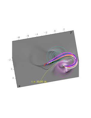
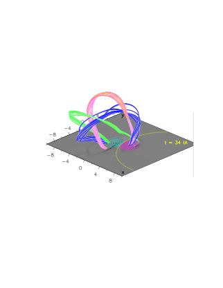
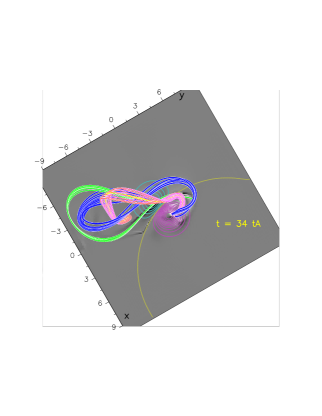
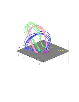
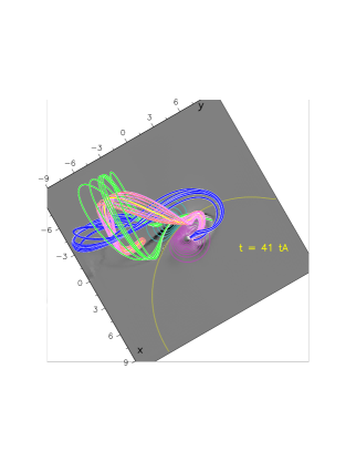
The evolution of the flux rope envelope is shown in Fig.17. There, we have represented a set of field lines in pink representing the unstable flux rope core present from the beginning of the simulation. Another set of field lines, reconnecting between and , is shown in blue. These lines are actually the same set of field lines that are slipping from to in Fig.16. Finally, green represent field lines reconnecting at a later time, between to . We note that field lines reconnecting at later times surround the field lines already reconnected, i.e., the green lines are winding around both the pink and blue ones. Note also that as the flux rope expands, the whole structure becomes increasingly stretched, leading to almost vertical field lines near their footpoints at the photosphere, as is apparent from the side view in Fig. 17 (left column) at .
The top view shown in the right panel of Fig.17 can be compared directly with observations of the flare (Fig.3, arrows 2 and 3; Fig. 5). These long, hot loops appearing on the sides of the active region are added to the whole flux rope structure by the periphery and constitute its envelope (Fig. 5). The flux rope core itself is not visible.
The mechanism behind these erupting loops can be understood when looking at the top view (right panel) of Fig.17. The flux rope tends to erupt in a privileged direction (green lines in Fig. 17). In the simulation, this privileged direction is north-east. In the observations, the erupting loops also have a preferential direction, although this is south-west (Arrow 2 in Fig. 3). The existence of a privileged direction arises due to the asymmetry of the flux rope expansion, but can be constrained by the surrounding magnetic field, as observed here and described in Sect. 2. Moreover, the green field lines are seen to erupt in the model from to . This shows that only parts of the flux rope erupt at different times, explaining the appearance of erupting loops on the west (arrow 2) at 15:40:08 UT before those on the east (arrow 3) at 16:10:08 UT as shown in Fig.3. Therefore, the classical approach to flux rope ejection, as described in McKenzie & Canfield (2008) is not complete: the flux rope is continuously fed by on-going reconnection, leading to different sets of field lines constituting the flux rope envelope having their own ejection dynamics.
5. Radio Observations and Interpretation
To gain more insight into the nature of the slipping reconnection process, we analysed the available radio data for the flare. These also complement the EUV observations from SDO/AIA.
At about 15:00 UT, radio burst activity started as a noise storm in the 200–500 MHz range (Fig. 18, first row). The noise storm was observed by the Callisto instrument (Benz et al., 2009; Monstein, 2013) in Trieste and consisted of a group of narrowband bursts resembling narrowband type III bursts. Some of the individual bursts exhibited drifts towards lower and some to higher frequencies. The typical frequency drifts of these bursts, which are about 20 MHz s-1, are more than an order of magnitude smaller than the typical mean frequency drift of the type III bursts, which is about 360 MHz s-1 (Alvarez & Haddock, 1973). This means that the velocity of the electron beams generating the noise storm bursts is more than an order of magnitude slower than for type III radio bursts, which is about /3, where is the speed of light.
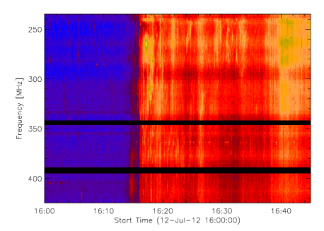
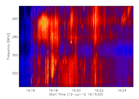
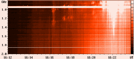
The noise storm lasted until 16:16 UT, when the strong radio flare started. The beginning of the strong radio flare is marked with two drifting pulsation structures (DPSs, e.g., Karlický et al., 2002; Karlický, 2004) occurring during 16:16–16:21 UT: one starting at 1.3 GHz and the other one at 1.0 GHz (Fig. 18, bottom row). Since these frequencies are not in harmonic relationship, this indicates spatially separated plasmoids. Both these DPSs drifted towards lower frequencies with the frequency drift d/d = 0.8 MHz s-1. Based on the timing, we identify them with the eruption of the series of long S-shaped loops observed by AIA (Fig. 5). Note also that at about 16:16:30 UT, several DPSs also appeared in the 250–300 MHz range (Fig. 18, third row), c.f. Karlický (2004), indicating a range of erupting structures with different densities.
At 16:16:30 UT, broadband radio continuum was registered in the range of 1–5 GHz simultaneously with the DPSs. The 1–5 GHz radio emission peaked at about 16:22 UT. After a short decrease at about of 16:24 UT the radio emission increased to its main maximum at 16:26 UT. At the lower frequencies (200–500 MHz), the main maximum occurred at about 16:40 UT.
The bursty nature of the radio emission in both the noise storm and the DPSs shows that the reconnection during the flare is intermittent and that the energy release leading to plasma heating is not uniformly distributed in time or space. This is already hinted at by the EUV observations from AIA (Sect. 2), which showed discrete, apparently moving features in all filters, rather than a continuous, near-uniform heating over the spatial locations (ribbons) where the slipping motion of the field line footpoints is occurring. Furthermore, presence of the DPSs during the impulsive phase indicates (1) presence of a current sheet and its fragmentation, (2) enhancement of the reconnection rate (Kliem et al., 2000; Bárta et al., 2008, 2011) at 16:16 UT, and that (3) the fast reconnection is not of the Petschek (1964) type, but turbulent with plasmoids in 3D (Daughton et al., 2011a, b). Note that the 3D MHD model of Aulanier et al. (2012) does not have sufficient spatial resolution to resolve the individual small-scale processes within the current sheet. Furthermore, since the model is pressureless, it does not include spatial and temporal distributions of plasma heating and particle acceleration. Therefore, the radio data give an important complementary information to the flare physics treated by the 3D MHD model.
6. Summary and Discussion
We have presented observations of an eruptive X1.4 long-duration flare that occurred on July 12, 2012 in active region 11520, which is a part of an active region complex. The observations were compared to the 3D MHD “standard solar flare model” of Aulanier et al. (2012). The model qualitatively allows for an explanation of the observed apparent slipping motion of both the flare and erupting loops in terms of a torus-unstable erupting flux rope that is fed continually by the slipping magnetic reconnection.
The flare itself is preceded by a brightening of several loop systems located in active region 11521. Using magnetic field extrapolations, we found that one of these loop systems shares the footpoint of a quasi-separatrix layer corresponding to the positive-polarity flare ribbon PR.
The flare starts with the appearance of a highly sheared flare loop in AIA 131Å, outlying an active region filament F1 seen in 304Å. This flare loop appears in a pre-existing coronal sigmoid. It subsequently develops into an arcade of flare loops, with individual loops exhibiting apparent slipping motion. In the early stages of the flare, there are several episodes when the slipping motion is clearly visible. This apparent slipping motion is of the order of several tens of km s-1 and is most pronounced in the flare loop footpoints located in the ribbon in the trailing negative polarities. Transition region emission from the loop footpoints is clearly identifiable in 171Å, 304Å and 1600Å from the beginning of the flare. These footpoints represent the first signature of the ribbon and subsequent local brightenings along the developing ribbon.
A number of the flare loops observed in 131Å expand in the SW direction and subsequently erupt. These loops connect both flare ribbons and contain a series of faint, S-shaped non-potential loops more than 250 long. The footpoints of the erupting loops are seen to slip along the extended hook of the positive-polarity ribbon with a velocity of approximately 136 km s-1. A CME is subsequently observed by the STEREO spacecrafts.
The DEM analysis method of Hannah & Kontar (2012) was applied to each AIA pixel in a limited field of view. It confirms that both the apparently slipping and erupting flare loops emit strongly in Fe XXI, originating around 10 MK. This emission is seen in the 131Å channel. Portions of these loops are also visible in the 94Å or 193Å channels, dominated by contributions from Fe XVIII, Ca XVII and Fe XXIV. A DEM analysis leads to an estimation of these contributions. We show that the flare loops do indeed emit in Fe XXIV. This emission is, except for a portion of the flare loops above the inversion line, obscured by much stronger Fe XII emission coming from the moss and warm coronal loops.
The observations have been qualitatively explained by a 3D pressureless MHD simulation of Aulanier et al. (2012) and Janvier et al. (2013). In this simulation, a torus-unstable flux rope is located within an active region exhibiting flux imbalance similarly to our observations. The simulation does not contain null points or separatrices, but the presence of quasi-separatrix layers leads to a slipping reconnection regime. That is, the field lines with one fixed footpoint in a QSL exhibit an apparent slipping motion of the footpoint in the conjugate QSL. The direction of the slipping predicted by the model is consistent with the observations. The difference between the simulated and observed velocities may be caused by the difference between the timescales of the slipping motion and chromospheric evaporation, as the flare loops must first be filled with heated plasma in order to be observable. Alternatively, the slipping reconnection during the flare can happen in thicker QSLs, involving sub-Alfvénic flare loop slipping motion, as suggested in Aulanier et al. (2007), instead of apparent super-Alfvénic motion in thin QSLs as in Janvier et al. (2013).
The QSL footpoints in the simulation are in the shape of a hook, with a straight portion in the strong photospheric magnetic field, and a curved hook portion located further away. The simulated slipping motion is faster in the hook, in agreement with the observations. During the simulation, the hook evolves and becomes rounder. The presence of a hook and its evolution is reflected in the observations, with the exception that large-scale magnetic field constricts the negative-polarity hook and does not allow it to become round. Instead, the hook is deformed because of the presence of a large-scale QSL and extends more than 100 to the south. The EUV intensity of the ribbon hook is lower than that of the straight portion of the ribbon, which can be understood in terms of energy deposition. The slipping motion is faster in the hook than in the straight part of the QSL in both the observations and the simulation, resulting in a lower amount of energy per unit time and area available for chromospheric evaporation.
The flux rope in the simulation is unstable and expands, which leads to its eruption. As the reconnection proceeds, the flux rope is fed with newly reconnected field lines that participate in the eruption. The flux rope envelope is observed by the AIA as long, S-shaped erupting hot loops. The erupting flux rope has a preferential direction in both the model and observations. In the observations this direction is modified by the large-scale magnetic field not present in the model.
An interesting feature of the flare is that despite the presence of an erupting flux rope and a flare arcade, the filament F1 remains unperturbed during the entire flare. This suggests that the real flare configurations may be complicated by the presence of another, filament-related flux rope that does not evolve with the rest of the magnetic configuration, in particular the overlying sigmoid. We note that although there are magnetic dips close to the photosphere in the simulation (Aulanier et al., 2012, Fig. 6 therein), these are part of the sigmoid and not of any additional flux rope. This additional flux rope must then be connected to the topological complexity of real solar magnetic fields, as opposed to the simplified modelled ones. We also note that such tightly-packed flux-ropes constituting active-region filaments have indeed been recently reported by Kuckein et al. (2012) and Yelles Chaouche et al. (2012).
The apparent motion of EUV loops in early stages of the flare, interpreted by the slipping reconnection, was associated with the noise storm in the metric radio range. The noise storm ended at 16:16 UT with the appearance of the dm-drifting pulsation structures, indicating plasmoid formation within the flare current sheet and their subsequent ejection. This marks the enhancement of the reconnection rate and the impulsive phase of the flare, as evidenced by radio bursts observed in very broad range of radio frequencies. Note that at this instant the long S-shaped loop erupted and the GOES X-ray flux rapidly increased.
In summary, we have shown that the apparent slipping motion as a result of slipping reconnection, is indeed occurring during eruptive flares. This motion is a typical feature of the “standard solar flare model in 3D”, which allows for a consistent explanation of many of the individual magnetically-controlled phenomena during the eruptive flares. It also shows that null-points and true separatrices are not required for the eruptive flares to occur. Radio data indicate that the slipping reconnection is also associated with intermittent particle acceleration and plasmoid formation.
References
- Alexander et al. (2013) Alexander, C. E., Walsh, R. W., Régnier, S., et al. 2013, ApJ, 775, L32
- Alissandrakis (1981) Alissandrakis, C. E. 1981, A&A, 100, 197
- Alvarez & Haddock (1973) Alvarez, H., & Haddock, F. T. 1973, Sol. Phys., 29, 197
- Amari et al. (2000) Amari, T., Luciani, J. F., Mikic, Z., & Linker, J. 2000, ApJ, 529, L49
- Andretta et al. (2003) Andretta, V., Del Zanna, G., & Jordan, S. D. 2003, A&A, 400, 737
- Antiochos et al. (1999) Antiochos, S. K., DeVore, C. R., & Klimchuk, J. A. 1999, ApJ, 510, 485
- Aschwanden & Boerner (2011) Aschwanden, M. J., & Boerner, P. 2011, ApJ, 732, 81
- Asplund et al. (2009) Asplund, M., Grevesse, N., Sauval, A. J., & Scott, P. 2009, ARA&A, 47, 481
- Aulanier et al. (2005) Aulanier, G., Démoulin, P., & Grappin, R. 2005, A&A, 430, 1067
- Aulanier et al. (2012) Aulanier, G., Janvier, M., & Schmieder, B. 2012, A&A, 543, A110
- Aulanier et al. (2006) Aulanier, G., Pariat, E., Démoulin, P., & DeVore, C. R. 2006, Sol. Phys., 238, 347
- Aulanier et al. (2010) Aulanier, G., Török, T., Démoulin, P., & DeLuca, E. E. 2010, ApJ, 708, 314
- Aulanier et al. (2007) Aulanier, G., Golub, L., DeLuca, E. E., et al. 2007, Science, 318, 1588
- Aurass et al. (2011) Aurass, H., Mann, G., Zlobec, P., & Karlický, M. 2011, ApJ, 730, 57
- Bárta et al. (2011) Bárta, M., Büchner, J., Karlický, M., & Skála, J. 2011, ApJ, 737, 24
- Bárta et al. (2008) Bárta, M., Vršnak, B., & Karlický, M. 2008, A&A, 477, 649
- Benz et al. (2009) Benz, A. O., Monstein, C., Meyer, H., et al. 2009, Earth Moon and Planets, 104, 277
- Boerner et al. (2012) Boerner, P., Edwards, C., Lemen, J., et al. 2012, Sol. Phys., 275, 41
- Brosius (2013) Brosius, J. W. 2013, ApJ, 762, 133
- Brosius & Holman (2010) Brosius, J. W., & Holman, G. D. 2010, ApJ, 720, 1472
- Carmichael (1964) Carmichael, H. 1964, NASA Special Publication, 50, 451
- Chandra et al. (2009) Chandra, R., Schmieder, B., Aulanier, G., & Malherbe, J. M. 2009, Sol. Phys., 258, 53
- Chen et al. (2012) Chen, P. F., Su, J. T., Guo, Y., & Deng, Y. Y. 2012, Chi. Sci. Bull., 57, 1393
- Cheng et al. (2013) Cheng, X., Zhang, J., Ding, M. D., Liu, Y., & Poomvises, W. 2013, ApJ, 763, 43
- Chifor et al. (2006) Chifor, C., Mason, H. E., Tripathi, D., Isobe, H., & Asai, A. 2006, A&A, 458, 965
- Craig & Brown (1976) Craig, I. J. D., & Brown, J. C. 1976, A&A, 49, 239
- Craig & Brown (1986) Craig, I. J. D., & Brown, J. C. 1986, Inverse problems in astronomy: A guide to inversion strategies for remotely sensed data (Adam Hilger, Ltd., 159 p.)
- Daughton et al. (2011a) Daughton, W., Roytershteyn, V., & Karimabadi, H. 2011a, in APS Meeting Abstracts, 9016P
- Daughton et al. (2011b) Daughton, W., Roytershteyn, V., Karimabadi, H., et al. 2011b, in American Institute of Physics Conference Series, Vol. 1320, American Institute of Physics Conference Series, ed. D. Vassiliadis, S. F. Fung, X. Shao, I. A. Daglis, & J. D. Huba, 144–159
- del Zanna (1999) del Zanna, G. 1999, PhD thesis, , Univ. of Central Lancashire, (1999)
- Del Zanna (2013) Del Zanna, G. 2013, A&A, 558, A73
- Del Zanna et al. (2011a) Del Zanna, G., Aulanier, G., Klein, K.-L., & Török, T. 2011a, A&A, 526, A137
- Del Zanna et al. (2011b) Del Zanna, G., Mitra-Kraev, U., Bradshaw, S. J., Mason, H. E., & Asai, A. 2011b, A&A, 526, A1
- Del Zanna et al. (2011c) Del Zanna, G., O’Dwyer, B., & Mason, H. E. 2011c, A&A, 535, A46
- Démoulin et al. (1997) Démoulin, P., Bagala, L. G., Mandrini, C. H., Hénoux, J. C., & Rovira, M. G. 1997, A&A, 325, 305
- Démoulin et al. (1996) Démoulin, P., Hénoux, J. C., Priest, E. R., & Mandrini, C. H. 1996, A&A, 308, 643
- Démoulin et al. (1996) Démoulin, P., Priest, E. R., & Lonie, D. P. 1996, J. Geophys. Res., 101, 7631
- Dere et al. (1999) Dere, K. P., Brueckner, G. E., Howard, R. A., Michels, D. J., & Delaboudiniere, J. P. 1999, ApJ, 516, 465
- Dere et al. (1997) Dere, K. P., Landi, E., Mason, H. E., Monsignori Fossi, B. C., & Young, P. R. 1997, A&AS, 125, 149
- Doschek et al. (2013) Doschek, G. A., Warren, H. P., & Young, P. R. 2013, ApJ, 767, 55
- Elgaroy (1977) Elgaroy, O. 1977, Solar noise storms, 43
- Fan (2012) Fan, Y. 2012, ApJ, 758, 60
- Fletcher et al. (2011) Fletcher, L., Dennis, B. R., Hudson, H. S., et al. 2011, Space Sci. Rev., 159, 19
- Gary (1989) Gary, G. A. 1989, ApJS, 69, 323
- Gekelman et al. (2012) Gekelman, W., Lawrence, E., & Van Compernolle, B. 2012, ApJ, 753, 131
- Graham et al. (2011) Graham, D. R., Fletcher, L., & Hannah, I. G. 2011, A&A, 532, A27
- Green & Kliem (2009) Green, L. M., & Kliem, B. 2009, ApJ, 700, L83
- Green et al. (2011) Green, L. M., Kliem, B., & Wallace, A. J. 2011, A&A, 526, A2
- Hannah & Kontar (2012) Hannah, I. G., & Kontar, E. P. 2012, A&A, 539, A146
- Hannah & Kontar (2013) —. 2013, A&A, 553, A10
- Hirayama (1974) Hirayama, T. 1974, Sol. Phys., 34, 323
- Inglis & Gilbert (2013) Inglis, A. R., & Gilbert, H. R. 2013, ArXiv e-prints
- Janvier et al. (2013) Janvier, M., Aulanier, G., Pariat, E., & Démoulin, P. 2013, A&A, 555, A77
- Jiang et al. (2011) Jiang, Y., Yang, J., Hong, J., Bi, Y., & Zheng, R. 2011, ApJ, 738, 179
- Judge et al. (1997) Judge, P. G., Hubeny, V., & Brown, J. C. 1997, ApJ, 475, 275
- Kane (1974) Kane, S. R. 1974, in IAU Symposium, Vol. 57, Coronal Disturbances, ed. G. A. Newkirk, 105–141
- Karlický (2004) Karlický, M. 2004, A&A, 417, 325
- Karlický & Bárta (2007) Karlický, M., & Bárta, M. 2007, A&A, 464, 735
- Karlický & Bárta (2011) —. 2011, ApJ, 733, 107
- Karlický et al. (2012) Karlický, M., Bárta, M., & Nickeler, D. 2012, A&A, 541, A86
- Karlický et al. (2010) Karlický, M., Bárta, M., & Rybák, J. 2010, A&A, 514, A28
- Karlický et al. (2002) Karlický, M., Fárník, F., & Mészárosová, H. 2002, A&A, 395, 677
- Kliem et al. (2000) Kliem, B., Karlický, M., & Benz, A. O. 2000, A&A, 360, 715
- Kliem et al. (2010) Kliem, B., Linton, M. G., Török, T., & Karlický, M. 2010, Sol. Phys., 266, 91
- Kołomański & Karlický (2007) Kołomański, S., & Karlický, M. 2007, A&A, 475, 685
- Kopp & Pneuman (1976) Kopp, R. A., & Pneuman, G. W. 1976, Sol. Phys., 50, 85
- Kuckein et al. (2012) Kuckein, C., Martínez Pillet, V., & Centeno, R. 2012, A&A, 539, A131
- Labrosse et al. (2010) Labrosse, N., Heinzel, P., Vial, J.-C., et al. 2010, Space Sci. Rev., 151, 243
- Landi et al. (2013) Landi, E., Young, P. R., Dere, K. P., Del Zanna, G., & Mason, H. E. 2013, ApJ, 763, 86
- Lemen et al. (2012) Lemen, J. R., Title, A. M., Akin, D. J., et al. 2012, Sol. Phys., 275, 17
- Lin & Forbes (2000) Lin, J., & Forbes, T. G. 2000, J. Geophys. Res., 105, 2375
- Liu et al. (2009) Liu, C., Lee, J., Karlický, M., et al. 2009, ApJ, 703, 757
- Loureiro et al. (2012) Loureiro, N. F., Samtaney, R., Schekochihin, A. A., & Uzdensky, D. A. 2012, Physics of Plasmas, 19, 042303
- Lynch et al. (2008) Lynch, B. J., Antiochos, S. K., DeVore, C. R., Luhmann, J. G., & Zurbuchen, T. H. 2008, ApJ, 683, 1192
- Magara et al. (1996) Magara, T., Mineshige, S., Yokoyama, T., & Shibata, K. 1996, ApJ, 466, 1054
- Masson et al. (2012) Masson, S., Aulanier, G., Pariat, E., & Klein, K.-L. 2012, Sol. Phys., 276, 199
- Masson et al. (2009) Masson, S., Pariat, E., Aulanier, G., & Schrijver, C. J. 2009, ApJ, 700, 559
- McKenzie & Canfield (2008) McKenzie, D. E., & Canfield, R. C. 2008, A&A, 481, L65
- Mészárosová et al. (2013) Mészárosová, H., Dudík, J., Karlický, M., Madsen, F. R. H., & Sawant, H. S. 2013, Sol. Phys., 283, 473
- Milligan & Dennis (2009) Milligan, R. O., & Dennis, B. R. 2009, ApJ, 699, 968
- Milligan et al. (2010) Milligan, R. O., McAteer, R. T. J., Dennis, B. R., & Young, C. A. 2010, ApJ, 713, 1292
- Monstein (2013) Monstein, C. 2013, in EGU General Assembly Conference Abstracts, Vol. 15, EGU General Assembly Conference Abstracts, 2027
- Moore et al. (1997) Moore, R. L., Schmieder, B., Hathaway, D. H., & Tarbell, T. D. 1997, Sol. Phys., 176, 153
- Moore et al. (2001) Moore, R. L., Sterling, A. C., Hudson, H. S., & Lemen, J. R. 2001, ApJ, 552, 833
- Neupert (1968) Neupert, W. M. 1968, ApJ, 153, L59
- Ning (2011) Ning, Z. J. 2011, in Astronomical Society of India Conference Series, Vol. 2, Astronomical Society of India Conference Series, 279
- O’Dwyer et al. (2010) O’Dwyer, B., Del Zanna, G., Mason, H. E., Weber, M. A., & Tripathi, D. 2010, A&A, 521, A21
- Ohyama & Shibata (1998) Ohyama, M., & Shibata, K. 1998, ApJ, 499, 934
- Pariat & Démoulin (2012) Pariat, E., & Démoulin, P. 2012, A&A, 541, A78
- Parker (1957) Parker, E. N. 1957, J. Geophys. Res., 62, 509
- Patsourakos et al. (2013) Patsourakos, S., Vourlidas, A., & Stenborg, G. 2013, ApJ, 764, 125
- Petkaki et al. (2012) Petkaki, P., Del Zanna, G., Mason, H. E., & Bradshaw, S. J. 2012, A&A, 547, A25
- Petschek (1964) Petschek, H. E. 1964, NASA Special Publication, 50, 425
- Poduval et al. (2013) Poduval, B., DeForest, C. E., Schmelz, J. T., & Pathak, S. 2013, ApJ, 765, 144
- Priest & Forbes (2000) Priest, E., & Forbes, T. 2000, Magnetic Reconnection
- Priest & Démoulin (1995) Priest, E. R., & Démoulin, P. 1995, J. Geophys. Res., 1002, 23443
- Priest et al. (2003) Priest, E. R., Hornig, G., & Pontin, D. I. 2003, Journal of Geophysical Research (Space Physics), 108, 1285
- Raftery et al. (2009) Raftery, C. L., Gallagher, P. T., Milligan, R. O., & Klimchuk, J. A. 2009, A&A, 494, 1127
- Reid et al. (2012) Reid, H. A. S., Vilmer, N., Aulanier, G., & Pariat, E. 2012, A&A, 547, A52
- Savcheva et al. (2012) Savcheva, A., Pariat, E., van Ballegooijen, A., Aulanier, G., & DeLuca, E. 2012, ApJ, 750, 15
- Scherrer et al. (2012) Scherrer, P. H., Schou, J., Bush, R. I., et al. 2012, Sol. Phys., 275, 207
- Schmelz et al. (2013) Schmelz, J. T., Jenkins, B. S., & Pathak, S. 2013, ApJ, 770, 14
- Schmelz et al. (2012) Schmelz, J. T., Reames, D. V., von Steiger, R., & Basu, S. 2012, ApJ, 755, 33
- Schmieder et al. (1996) Schmieder, B., Heinzel, P., van Driel-Gesztelyi, L., & Lemen, J. R. 1996, Sol. Phys., 165, 303
- Schrijver et al. (2013) Schrijver, C. J., Title, A. M., Yeates, A. R., & DeRosa, M. L. 2013, ArXiv e-prints
- Shen et al. (2012) Shen, Y., Liu, Y., & Su, J. 2012, ApJ, 750, 12
- Shibata & Tanuma (2001) Shibata, K., & Tanuma, S. 2001, Earth, Planets, and Space, 53, 473
- Sturrock (1966) Sturrock, P. A. 1966, Nature, 211, 695
- Sweet (1958) Sweet, P. A. 1958, in IAU Symposium, Vol. 6, Electromagnetic Phenomena in Cosmical Physics, ed. B. Lehnert, 123
- Testa et al. (2013) Testa, P., De Pontieu, B., Martínez-Sykora, J., et al. 2013, ApJ, 770, L1
- Titov et al. (2002) Titov, V. S., Hornig, G., & Démoulin, P. 2002, Journal of Geophysical Research (Space Physics), 107, 1164
- Török et al. (2004) Török, T., Kliem, B., & Titov, V. S. 2004, A&A, 413, L27
- Török et al. (2011) Török, T., Panasenco, O., Titov, V. S., et al. 2011, ApJ, 739, L63
- Uzdensky et al. (2010) Uzdensky, D. A., Loureiro, N. F., & Schekochihin, A. A. 2010, Physical Review Letters, 105, 235002
- van Ballegooijen & Martens (1989) van Ballegooijen, A. A., & Martens, P. C. H. 1989, ApJ, 343, 971
- Warren & Warshall (2001) Warren, H. P., & Warshall, A. D. 2001, ApJ, 560, L87
- Wheatland (2006) Wheatland, M. S. 2006, Sol. Phys., 236, 313
- White et al. (2011) White, S. M., Benz, A. O., Christe, S., et al. 2011, Space Sci. Rev., 159, 225
- Wilmot-Smith et al. (2009) Wilmot-Smith, A. L., Hornig, G., & Pontin, D. I. 2009, ApJ, 704, 1288
- Wuelser et al. (2004) Wuelser, J.-P., Lemen, J. R., Tarbell, T. D., et al. 2004, in Society of Photo-Optical Instrumentation Engineers (SPIE) Conference Series, Vol. 5171, Society of Photo-Optical Instrumentation Engineers (SPIE) Conference Series, ed. S. Fineschi & M. A. Gummin, 111–122
- Yelles Chaouche et al. (2012) Yelles Chaouche, L., Kuckein, C., Martínez Pillet, V., & Moreno-Insertis, F. 2012, ApJ, 748, 23
- Young et al. (2013) Young, P. R., Doschek, G. A., Warren, H. P., & Hara, H. 2013, ApJ, 766, 127
- Zhang et al. (2012) Zhang, J., Cheng, X., & Ding, M.-D. 2012, Nature Communications, 3
- Zuccarello et al. (2009) Zuccarello, F., Romano, P., Farnik, F., et al. 2009, A&A, 493, 629
- Zweibel & Yamada (2009) Zweibel, E. G., & Yamada, M. 2009, ARA&A, 47, 291