Optimizing a spin-flip Zeeman slower
Abstract
We present a design of a spin-flip Zeeman slower controlled by a fast feedback circuit for a sodium Bose-Einstein condensate apparatus. We also demonstrate how the efficiency of the slower strongly depends on its intrinsic parameters, and compare these observations with a few theoretical models. Our findings lead to a simple three-step procedure of designing an optimal Zeeman slower for neutral atoms, especially for those atomic species with high initial velocities, such as sodium and lithium atoms.
pacs:
020.3320, 020.7010, 020.7490, 020.0020I Introduction
Laser cooling and trapping neutral atoms with a magneto-optical trap (MOT) has become an important step in a successful production of ultracold quantum gases mot . To improve the capture efficiency of a MOT, a number of slowers were invented to slow hot atoms before they overlap with the MOT ketterle ; mot ; durfee ; phillips ; naik ; gibble . Atoms and a resonant laser beam counter propagate in a slower. The longitudinal velocity and corresponding Doppler shift of these atoms decrease after they absorb resonant photons. After a few such absorptions, these slowed atoms are no longer resonant with the laser beam and thus cannot be further slowed down. In order to continuously slow atoms along the laser beam path, one can vary the laser frequency accordingly as with the frequency chirp method Wallis or by using broadband lasers zhu . Another widely-used method is to compensate differences in the Doppler shift with a spatially varying magnetic field generated by a Zeeman slower while keeping the laser frequency unchanged mot ; durfee ; phillips ; Stamper-Kurn2010 ; cheiney ; bell ; naik ; slower2004 ; Meschede1999 . In this paper, we present the design and construction of a spin-flip Zeeman slower controlled by a fast feedback circuit for a sodium Bose-Einstein condensate (BEC) apparatus. An efficient method of optimizing a slower with our simulation program and by monitoring the number of atoms trapped in the MOT is also explained. In addition, our data demonstrates how the efficiency of a slower strongly depends on a few of its intrinsic parameters, such as the intensity of the slowing laser beam and the length of each section in the slower. These findings result in a simple three-step procedure of designing an optimal Zeeman slower for neutral atoms, especially for those atomic species with high initial velocities, for example lithium atoms.
II Experimental Setup
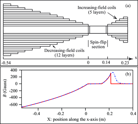
A sodium beam is created by an oven consisting of a half nipple and an elbow flange. A double-sided flange with a 6 mm diameter hole in the center is used to collimate the atomic beam. To collect scattered atoms, a cold plate with a 9 mm diameter center hole is placed before a spin-flip Zeeman slower and kept at 10 ∘C with a Peltier cooler. Our multi-layer slower has three different sections along the axis (i.e., a decreasing-field section, a spin-flip section, and an increasing-field section), as shown in Fig. 1(a). Compared with the single-layer Zeeman slower with variable pitch coils bell , this multi-layer design provides us enormous flexibilities in creating large enough for slowing atoms with high initial velocities (e.g., sodium and lithium atoms). The first section of our Zeeman slower produces a magnetic field with decreasing magnetic field strength . We choose Gauss at the entrance of the slower, so the slowing beam only needs to be red-detuned by of a few hundred MHz from the D2 line of 23Na atoms. This frequency detuning is easily achieved with an acousto-optic modulator, but is still large enough to avoid perturbing the MOT. The spin-flip section is simply a bellow as to maintain for atoms to be fully re-polarized and also to damp out mechanical vibrations generated by vacuum pumps. The increasing-field section creates a magnetic field with increasing but in the opposite direction to that of the decreasing-field section, which ensures the magnetic field quickly dies off outside the slower. This slower can thus be placed close to the MOT, which results in more atoms being captured. The MOT setup is similar to that of our previous work JiangBEC and its maximum capture velocity is 50 m/s.
To precisely adjust inside the slower, all layers of magnetic coils are divided into four groups, and different layers in each group are connected in series and controlled by one fast feedback circuit. A standard ring-down circuit consisting of a resistor and a diode is also connected in parallel with each coil for safely shutting off the inductive current in the coil. An important chip in our control circuit is a high power metal oxide semiconductor field effect transistor (MOSFET) operated in the linear mode. We use a number of MOSFETs connected in parallel and mount them on the top of a water-cooled cold plate to efficiently cool them. A carefully chosen resistor Rs of 50 m is connected to each MOSFET’s source terminal to encourage equal current splitting among the MOSFETs in parallel. Rs also limits MOSFET’s transconductance to a narrow range, which enables our feedback circuit to control both low and high electric currents with a single set of gains. The design of this feedback circuit is available upon request.
III Optimization
When neutral atoms pass through the Zeeman slower, only those atoms with a longitudinal velocity are resonant with the slowing beam and can be slowed. Here is the magnetic moment, is the reduced Planck’s constant, and are the wavevector and frequency detuning of the laser beam, respectively. The actual deceleration in the slower is thus given by
| (1) |
where is a safe factor to account for magnetic field imperfections in a given slower and the finite intensity of the slowing laser beam, and is the maximal achievable deceleration. and are the mass and the natural linewidth of the atoms, respectively.
Our largest MOT is achieved when we match inside the slower as precisely as possible to a prediction derived from Eq. 1 with being set at 0.65 in decreasing- and increasing-field sections and 40 m/s, as shown in Fig. 1(b). Here is the velocity of atoms at the end of the slower. , the number of atoms in a MOT, can also be boosted by a larger atomic flux with a hotter atomic oven. However, this is generally not a favorable method due to two reasons. First, a hotter oven generates atoms with higher initial average velocities, but a slower can only handle entering atoms of a certain maximum velocity. Second, alkali metals’ consumption rates sharply increase with the oven temperature.
We find that convenient parameters to adjust are slowing beam’s intensity and frequency detuning , electric current in each magnetic coil, and the length of each section of the slower. These parameters, however, cannot be optimized independently since there is a strong correlation among them. In order to efficiently optimize the slower, we developed a computer program to simulate and compared the simulation results to the actual magnetic field strengths in the slower under many different conditions (e.g., at various values of ). The actual magnetic field strengths were measured with a precise Hall probe before the slower was connected to the vacuum apparatus. The agreements between the simulation results and the measurements are good, i.e., the discrepancies are 5 %. This simulation program can thus mimic the actual performance of a Zeeman slower and provide a reasonable tuning range for each aforementioned parameter, which allows for efficiently optimizing the slower. Our simulation program is available upon request.
One common way to evaluate a slower’s performance is from knowing the exact number of atoms whose velocities are smaller than with a costly resonant laser. In the next four subsections, we show that a convenient detection method of optimizing a slower is to monitor the number of atoms captured in the MOT, i.e., more atoms trapped in a given MOT setup indicate a better performance of the slower.
III.1 Intensity of the slowing beam
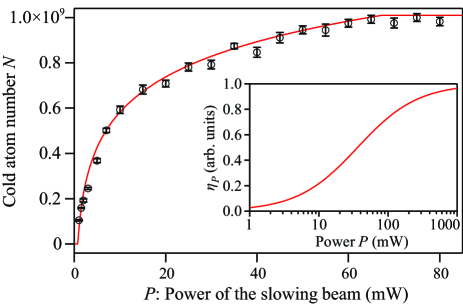
Figure 2 shows that the MOT capture efficiency strongly depends on the slowing beam power , i.e., increases with and then stays at its peak value when is higher than a critical value. This can be understood from the relationship between the safe factor of a slower and the slowing beam intensity . Based on Ref. Meschede1999 , the safe factor at a finite can be expressed as,
| (2) |
where is the saturation intensity of neutral atoms, e.g., it is for sodium atoms. Eq. 2 implies that the safe factor of any optimal Zeeman slower has an upper limit, , as long as the slowing beam intensity is fixed. In other words, a bigger in the decreasing- or increasing-field section does not always lead to a more efficient Zeeman slower if is given.
For a Gaussian slowing beam with a width , its intensity can be expressed as . Here is the distance away from the slowing beam center and is the beam intensity at . can be given by,
| (3) |
Here is a unit step function of to account for the fact that atoms can be efficiently slowed only when , and is the radius of the atomic beam. Figure 2 shows that our data taken with in decreasing- and increasing-field sections can be well fitted by Eq. 3 and saturates at mW. This indicates that 70 mW is the minimum power to achieve for our apparatus. We can thus define a , the preferred in decreasing- and increasing-field sections at a given , and derive its expression from Eq. 3 as follows,
| (4) |
The predicted as a function of for our apparatus is shown in the inset in Fig. 2, which implies sharply increases with and is infinitely large at . Therefore, the first step in designing an optimal Zeeman slower is to determine from Eq. 4 based on the available slowing beam power.
III.2 The decreasing-field section
To focus on the decreasing-field section, our data shown in this subsection are taken with being set at 0.65 in the increasing-field section, a fixed distance between the atomic oven and the MOT center to maintain a fixed solid angle for an atomic beam, MHz, and mW which implies is 0.65. Based on the discussions in Refs. durfee ; Stamper-Kurn2010 , can be expressed as
| (5) |
where is the initial number of atoms created by the oven, is the Boltzmann constant, and the oven temperature is set at 530 K in this work. is a correction factor to account for the transverse velocity distribution of slowed atoms after they absorb resonant photons in a Zeeman slower, which can be expressed as
| (6) |
Here is the radius of a MOT, is the distance between the MOT center and the end of a Zeeman slower, is the recoil velocity of an atom in a slowing process, and is the transverse velocity of slowed atoms Stamper-Kurn2010 . In Eq. 5, is the maximum velocity of entering atoms which can be handled by a slower. For a spin-flip Zeeman slower, is given by
| (7) |
where and are the length and the actual safe factor of the decreasing-field section, respectively. And is the velocity of atoms which are resonant with the slowing beam at the spin-flip section, since is zero in this section. For example, is 302 m/s at MHz in our sodium BEC apparatus.
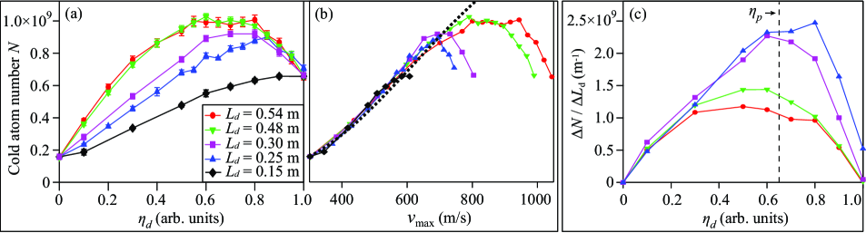
For a given , Eqs. 5-7 predict that should monotonically increase with , i.e., increases with at a fixed (or increases with at a fixed ). However, our observations shown in Fig. 3(a) are drastically different from this prediction: at each studied in this paper, appears to first increase with , reach its peak at a critical value of , and then decrease with . Based on Eq. 7, we can also plot these data points as a function of , as shown in Fig. 3(b). At each value of , the agreement between our data and a theoretical prediction derived from Eqs. 5-7 (dotted black line) can only be found when is smaller than m/s, which is approximately equal to the mean velocity ( ) of atoms entering our slower.
In addition, we plot as a function of in Fig. 3(c), where represents the number of extra atoms in the MOT gained from elongating the decreasing-field section by . Figure 3(c) shows that drops to a much smaller value when is increased from 0.3 m to 0.48 m. This implies the ideal length of the decreasing-field section for our apparatus should be longer than 0.3 m and shorter than 0.48 m. It is worth noting that peaks at for each value of , as shown in Fig. 3(c). Interestingly, the predicted from Eq. 4 is also 0.65 at 70 mW, and Fig. 3(a) shows is also the position where the largest occurs. This indicates that of our optimized decreasing-field section is actually equal to . Therefore, one important procedure in designing an optimal Zeeman slower is as follows: 1) find out based on Eq. 4 from the available slowing beam intensity; 2) determine the length of the decreasing-field section from Eq. 7, i.e., ; 3) find out electric currents of decreasing-field coils with our simulation program by precisely matching the simulated to a prediction derived from Eq. 1.
III.3 The increasing-field section
The aforementioned discussion on the decreasing-field section applies to the increasing-field section as well. To only study the increasing-field section, data shown in this subsection are taken at , , and 70 mW.
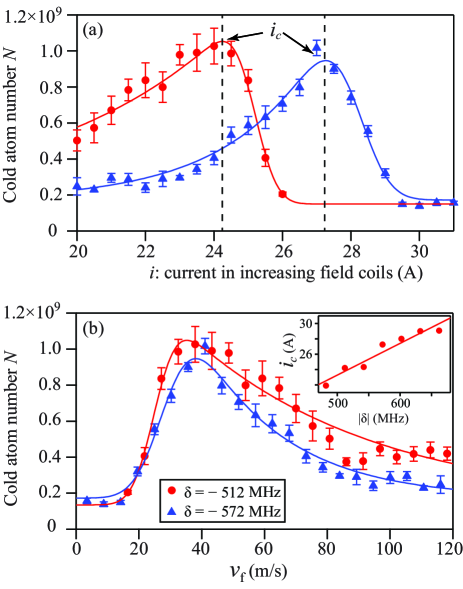
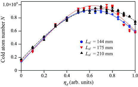
Our data in Fig. 4(a) shows that is not a monotonic function of at a given . first increases with and reaches a peak at a critical value , because a higher leads to a larger deceleration which means more atoms can be slowed and captured in the MOT. When is higher than , we find that sharply decreases with due to atoms being over-slowed. Because , the data points in Fig. 4(a) can be converted to reveal the relationship between and , as shown in Fig. 4(b). Here is the maximum magnetic field strength created by the increasing-field section at a fixed . We find four interesting results: always peaks around m/s at any within the range of ; the minimal velocity of the atoms captured in the MOT appears to be 20 m/s; the maximum value of does not depend on ; and linearly increases with , as shown in Fig. 4. Therefore, in addition to the procedures listed in Sections 3.A and 3.B, another useful procedure in designing an optimal spin-flip Zeeman slower is as follows: 1) choose a convenient , for example, is around for sodium or lithium atoms; 2) find out the ideal length of the increasing-field section from the following equation, ; 3) determine from a figure similar to Fig. 4(a) and then set the current at a value slightly smaller than in the increasing-field coils.
III.4 The spin-flip section
We have also studied the contribution of the spin-flip section, but have not found a strong correlation between the slower’s efficiency and , the length of the spin-flip section. Figure 5 shows that always peaks at for three different values of , when is kept at 0.54 m, is set at 0.65 in the increasing-field section, is , and is 70 mW. This figure also implies that a longer spin-flip section does not boost the number of atoms captured in the MOT, as long as its length is sufficient to fully re-polarize atoms. A very long , however, has a negative effect on the MOT capture efficiency, because it also unavoidably reduces the solid angle of the atomic beam when all other parameters of the system remain unchanged.
IV Conclusions
We have presented the design and construction of a spin-flip Zeeman slower controlled by a fast feedback circuit, and demonstrated an efficient method to optimize a slower by using our simulation program and monitoring the number of atoms trapped in the MOT. Our data suggests that an optimal Zeeman slower may be designed with the following procedures: 1) determine based on Eq. 4 from the available slowing beam intensity; 2) choose a convenient and find out the ideal lengths of the increasing- and decreasing-field sections from and , respectively; 3) set at a value slightly smaller than in the increasing-field coils and determine of decreasing-field coils with our simulation program. We have found that a longer spin-flip section does not boost the number of atoms captured in the MOT, as long as its length is sufficient to fully re-polarize atoms. These conclusions are very useful in designing an optimal Zeeman slower for other atomic species, especially those with high initial velocities, for example lithium atoms.
V Acknowledgments
We thank Ian Spielman and Karl Nelson for insightful discussions, and Jared Austin and Micah Webb for experimental assistances. We also thank the U. S. Army Research Office, Oklahoma Center for the Advancement of Science and Technology, and Oak Ridge Associated Universities for financial support.
References
- (1) H. Metcalf and P. Van Der Straten, Laser Cooling and Trapping, Graduate Texts in Contemporary Physics (Springer, 1999).
- (2) W. Ketterle, K. B. Davis, M. A. Joffe, A. Martin, and D. E. Pritchard, “High densities of cold atoms in a dark spontaneous-force optical trap,” Phys. Rev. Lett. 70, 2253–2256 (1993).
- (3) D. Durfee, “Dynamic properties of dilute bose-einstein condensation,” Ph.D. thesis, Massachusetts Institute of Technology (1999).
- (4) W. D. Phillips and H. Metcalf, “Laser deceleration of an atomic beam,” Phys. Rev. Lett. 48, 596–599 (1982).
- (5) D. S. Naik, “Bose-einstein condensation: Building the testbeds to study superfluidity,” Ph.D. thesis, Georgia Institute of Technology (2006).
- (6) K. E. Gibble, S. Kasapi, and S. Chu, “Improved magneto-optic trapping in a vapor cell,” Opt. Lett. 17, 526–528 (1992).
- (7) H. Wallis and W. Ertmer, “Fokker-planck analysis of atomic beam cooling by frequency chirp methods,” Journal of Physics B: Atomic, Molecular and Optical Physics 21, 2999 (1988).
- (8) M. Zhu, C. W. Oates, and J. L. Hall, “Continuous high-flux monovelocity atomic beam based on a broadband laser-cooling technique,” Phys. Rev. Lett. 67, 46–49 (1991).
- (9) G. E. Marti, R. Olf, E. Vogt, A. Öttl, and D. M. Stamper-Kurn, “Two-element zeeman slower for rubidium and lithium,” Phys. Rev. A 81, 043424 (2010).
- (10) P. Cheiney, O. Carraz, D. Bartoszek-Bober, S. Faure, F. Vermersch, C. M. Fabre, G. L. Gattobigio, T. Lahaye, D. Guéry-Odelin, and R. Mathevet, “A zeeman slower design with permanent magnets in a halbach configuration,” Review of Scientific Instruments 82, 063115 (2011).
- (11) S. C. Bell, M. Junker, M. Jasperse, L. D. Turner, Y.-J. Lin, I. B. Spielman, and R. E. Scholten, “A slow atom source using a collimated effusive oven and a single-layer variable pitch coil zeeman slower,” Review of Scientific Instruments 81, 013105 (2010).
- (12) C. J. Dedman, J. Nes, T. M. Hanna, R. G. Dall, K. G. H. Baldwin, and A. G. Truscott, “Optimum design and construction of a zeeman slower for use with a magneto-optic trap,” Review of Scientific Instruments 75, 5136–5142 (2004).
- (13) F. Lison, P. Schuh, D. Haubrich, and D. Meschede, “High-brilliance zeeman-slowed cesium atomic beam,” Phys. Rev. A 61, 013405 (1999).
- (14) J. Jiang, L. Zhao, M. Webb, N. Jiang, H. Yang, and Y. Liu, “Simple and efficient all-optical production of spinor condensates,” Phys. Rev. A 88, 033620 (2013).