High electric field development for the SNS nEDM Experiment
Abstract
A new experiment to search for the permanent electric dipole moment of the neutron is being developed for installation at the Spallation Neutron Source at Oak Ridge National Laboratory. This experiment will be performed in liquid helium at K and requires a large electric field ( kV/cm) to be applied in liquid helium. We have constructed a new HV test apparatus to study electric breakdown in liquid helium. Initial results demonstrated that it is possible to apply fields exceeding 100 kV/cm in a 1 cm gap between two electropolished stainless steel electrodes 12 cm in diameter for a wide range of pressures.
pacs:
84.70.+p, 77.22JpI Introduction
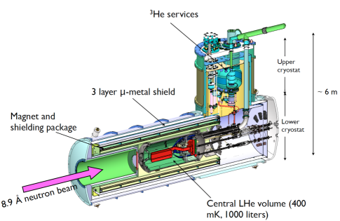
A nonzero permanent electric dipole moment (EDM) of a nondegenerate state of a system with spin violates time reversal invariance as well as invariance under parity operation. The time reversal invariance violation implies a CP violation through the theorem. Given the smallness of the standard model CP violating contributions induced by quark mixing, an EDM is a sensitive probe of new physics. A new experiment to search for the permanent EDM of the neutron, based on the method proposed by Golub and Lamoreaux GOL94 , is being developed to be mounted at the Spallation Neutron Source at Oak Ridge National Laboratory, with a sensitivity goal of cm, an improvement of roughy two orders of magnitude over the current limit BAK06 . For more details of the current status of this SNS nEDM experiment, see e.g. Ref. ITO07 . A schematic of the apparatus for the SNS nEDM experiment is shown in Fig. 1.
II HV requirements
The SNS nEDM experiment requires that a high, stable electric field ( kV/cm) be applied in the region inside the two measurement cells that are sandwiched between electrodes. The measurement cells and electrodes are immersed in 0.4 K liquid helium (LHe). The measurement cells, which store ultracold neutrons, are filled with isotopically pure liquid 4He at K (the relative 3He concentration ). The measurement cells are made of PMMA and are 10.16 cm 12.70 cm 42 cm in outer dimension with a wall thickness of 1.2 cm. The electrodes, roughly cm 40 cm 80 cm in size, are made of PMMA coated with a material that needs to meet various requirements related to electrical resistivity, neutron activation properties, and magnetic properties, etc. The leakage current along the cell walls need to be minimized.
III Some general remarks on electrical breakdown in LHe
Electrical breakdown in LHe, or more in general electrical breakdown in any dielectric liquid, is rather poorly understood. Data exist on electrical breakdown in LHe for temperatures of K (with the bulk of data being taken at 4.2 K) mostly at the saturated vapor pressure (SVP) for various electrode geometries, including sphere-to-sphere, sphere-to-plane, and plane-to-plane. However, there is little consistency among the data, and therefore there is no consistent theoretical interpretation.
However, a rather simple consideration of the mean free path of ions in LHe (electron bubbles and snow balls) and the electric field strength necessary to accelerate them to an energy sufficiently high to generate subsequent ionization leads to a conclusion that the intrinsic dielectric strength of bulk LHe is greater than 10 MV/cm, a field much higher than breakdown fields experimentally observed. This leads to the following generally-accepted picture for the mechanism of generation of electrical breakdown in LHe:
-
1.
A vapor bubble is formed on the surface of the electrode, e.g. by field emission from roughness on the cathode
-
2.
The vapor bubble grows, presumably by heating of the gas by accelerated electrons and evaporation of the liquid as a result, and forms a column of gas reaching from one electrode to the other
-
3.
Electrical breakdown occurs through the gas column
It follows that the parameters that can affect the breakdown field strength include: (i) electrode material, in particular the surface properties,and (ii) LHe temperature and pressure. In addition, because electrical breakdown is a stochastic process, the size of the system affects the breakdown field strength and its distribution. See e.g. Ref. WEB56 .
IV R&D approach
The consideration given above indicates that the R&D for the SNS nEDM experiment requires a study of electrical breakdown in LHe in a condition (i.e. temperature, pressure, size) as close as possible to that expected for the SNS nEDM experiment, using suitable candidate materials.
It is also very important to study the effect of the presence of a dielectric insulator sandwiched between electrodes, as such will be the geometry for the SNS nEDM experiment. Note that even in a room temperature vacuum system, electric fields exceeding a few 100 kV/cm are possible when there is no insulator between the two electrodes. In a study performed using a room temperature vacuum aparatus GOL86 similar to those used in the previous nEDM experiments (such as Ref. BAK06 ), the electric field was limited to kV/cm due to the presence of the UCN confining wall that was sandwiched between the two electrodes GOL86 111In the actual nEDM experiment, the achievable field was further lowered due to other factors. Field emission at the cathode-insulator junction is thought to be responsible for initiating breakdown KOF60 , which we expect to be suppressed at cryogenic temperatures.
In order to study the relevant aspects of electrical breakdown in LHe with a goal of establishing the feasibility of the SNS nEDM experiment as well as guiding the design of the apparatus, we constructed an apparatus called Medium Scale HV (MSHV) Test Apparatus, which is described below.
V Medium scale HV test apparatus
The purpose of the MSHV system is to study electrical breakdown in LHe in a condition approximating that of the SNS nEDM experiment using suitable electrode candidate materials. The lowest operating temperature of the MSHV system is designed to be 0.4 K, corresponding to the operating temperature of the SNS nEDM experiment. Since we expect that the pressure is an important parameter affecting the breakdown field strength in LHe, the MSHV system is designed so that the pressure of the LHe volume in which the electrodes are placed can be varied between the SVP and 1 atm. Note that the SVP is torr at 0.4 K. The size of the LHe volume was determined as a compromise between the following two competing factors:
-
•
Short turnaround time of the system ( weeks) to allow multiple electrode material candidates to be tested.
-
•
Size large enough to give information relevant for the SNS nEDM experiment.
The electrodes are 12 cm in diameter. The gap size is adjustable between 1 and 2 cm. Each dimension is within a factor of 10 of the SNS nEDM experiment’s HV system. A schematic of the MSHV system is shown in Fig. 2.
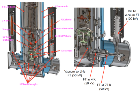
The Central Volume (CV), a 6-liter LHe volume that houses the electrodes, is cooled by a 3He refrigerator.
HV between kV and kV can be provided to each electrode through a HV feed line. The HV feed lines are made of thin wall stainless steel tubing and are thermally anchored at the LN2 heat shield and at the 4 K heat shield, in order to minimize the heat leak to the HV electrodes. Heat leak to the HV electrodes can cause vapor bubbles to be created on the surface of the electrodes, which in turn can initiate electrical breakdown, potentially leading to erronoues results.
Commercially available models are used for all the HV feedthroughs. For the air-to-vacuum feedthroughs, CeramTec Model 6722-01-CF feedthroughs, rated for 100 kV, are used. For all other feedthroughs, including ones on the CV that need to be superfluid tight, CeramTec Model 21183-01-W, rated for 50 kV and for LHe temperature operation, were chosen because the spatial limitations did not allow larger sized feedthroughs. In an offline test of these 50 kV feedthroughs, we found that, after proper cleaning, they can withstand a HV up to kV with a leakage current of less than 1 nA in vacuum when cooled to 77 K.
Most of HV components were tested in a separate system for holdoff voltage before being installed into the MSHV system. Our experience is that a component that functions in a room temperature vacuum generally functions in LHe.
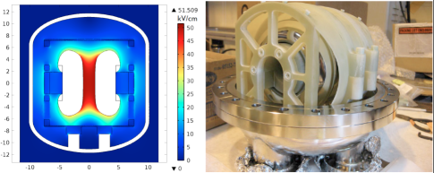
The initial electrodes are made of electropolished stainless steel and have the so-called Rogowski profile COB58 , which provides a uniform electric field in the gap and ensures that the gap has the highest field in the system (see Fig. 3).
VI Progress to date
We have successfully constructed and commissioned the MSHV system. We have demonstrated that the CV can be cooled to 0.4 K with it filled with LHe. We have also demonstrated that the pressure inside the CV can be varied and controlled easily.
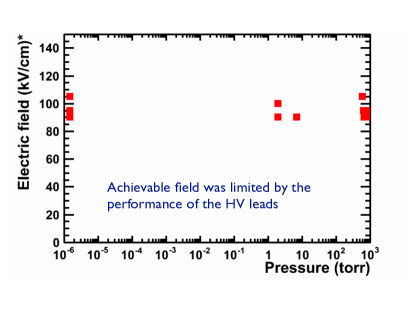
In addition, we have demonstrated that an electric field exceeding 100 kV/cm can be stably applied in a 1-cm gap between the two 12-cm diameter electrodes made of electropolished stainless steel for a wide range of pressures (see Fig. 4). The achievable field was limited by the performance of the HV leads. No breakdown was observed in the gap between the two electrodes. Also the leakage current between the two electrodes was measured to be less than 1 pA at a 50 kV potential difference. This was measured with one of the HV electrodes set to the ground potential to avoid the leakage current in the HV cable and feedthroughs dominating the measurement.
VII Summary
For the HV R&D for the SNS nEDM experiment, we have constructed a new HV test apparatus to study electrical breakdown in LHe. Initial results demonstrated that it is possible to apply fields exceeding 100 kV/cm in a 1 cm gap between two electropolished stainless steel electrodes 12 cm in diameter for a wide range of pressures.
References
- (1) R. Golub and S. K. Lamoreaux, Phys. Rep. 237, 1 (1994).
- (2) C. A. Baker et al., Phys. Rev. Lett. 97, 131801 (2006).
- (3) T. M. Ito, J. Phys. Conf. Ser. 69, 012037 (2007).
- (4) K. H. Weber and H. S. Endicott, Trans. Am. Inst. Elec. Eng. 75, 371 (1956)
- (5) R. Golub, Sov. Phys. Tech. Phys. 31 945 (1986).
- (6) M. J. Kofoid, Trans. Am. Inst. Elec. Eng. 79, 999 (1960).
- (7) J. D. Cobine, Gaseous Conductors: Theory and Engineering Applications (McGraw Hill, 1958)