NA61/SHINE facility at the CERN SPS:
beams and detector system
Abstract
NA61/SHINE (SPS Heavy Ion and Neutrino Experiment) is a multi-purpose experimental facility to study hadron production in hadron-proton, hadron-nucleus and nucleus-nucleus collisions at the CERN Super Proton Synchrotron. It recorded the first physics data with hadron beams in 2009 and with ion beams (secondary 7Be beams) in 2011.
NA61/SHINE has greatly profited from the long development of the CERN proton and ion sources and the accelerator chain as well as the H2 beamline of the CERN North Area. The latter has recently been modified to also serve as a fragment separator as needed to produce the Be beams for NA61/SHINE. Numerous components of the NA61/SHINE set-up were inherited from its predecessors, in particular, the last one, the NA49 experiment. Important new detectors and upgrades of the legacy equipment were introduced by the NA61/SHINE Collaboration.
This paper describes the state of the NA61/SHINE facility - the beams and the detector system - before the CERN Long Shutdown I, which started in March 2013.
1 Introduction
NA61/SHINE (SPS Heavy Ion and Neutrino Experiment) [1] is a multi-purpose facility to study hadron production in hadron-proton, hadron-nucleus and nucleus-nucleus collisions at the CERN Super Proton Synchrotron (SPS). The NA61/SHINE physics goals include:
-
(i)
study the properties of the onset of deconfinement [2] and search for the critical point of strongly interacting matter which is pursued by investigating p+p, p+Pb and nucleus-nucleus collisions and
- (ii)
The experiment was proposed to CERN in November 2006 [1]. Based on this proposal pilot data taking took place in September 2007. The Memorandum of Understanding [7] between CERN and the collaborating institutions was signed in October 2008. The first physics data with hadron beams were recorded in 2009 and with ion beams (secondary 7Be beams) in 2011. The first experimental results were published in [8, 9].
NA61/SHINE has greatly profited from the long development of the CERN proton and ion sources, the accelerator chain, as well as the H2 beamline of the CERN North Area. The latter has recently been modified to also serve as a fragment separator as needed to produce the Be beams for NA61/SHINE. Numerous components of the NA61/SHINE set-up were inherited from its predecessors, in particular, the last one, the NA49 experiment.
The layout of the NA61/SHINE detector is sketched in Fig. 1. It consists of a large acceptance hadron spectrometer with excellent capabilities in charged particle momentum measurements and identification by a set of six Time Projection Chambers as well as Time-of-Flight detectors. The high resolution forward calorimeter, the Projectile Spectator Detector, measures energy flow around the beam direction, which in nucleus-nucleus reactions is primarily a measure of the number of spectator (non-interacted) nucleons and thus related to the centrality of the collision. For hadron-nucleus interactions, the collision centrality is determined by counting low momentum particles emitted from the nuclear target with the LMPD detector (a small TPC) surrounding the target. An array of beam detectors identifies beam particles, secondary hadrons and ions as well as primary ions, and measures precisely their trajectories.

This paper describes the NA61/SHINE facility, the beams and the detector system. Special attention is paid to the presentation of the components which were constructed for NA61/SHINE. The components inherited from the past experiments and described elsewhere are presented only briefly here. The paper is organized as follows. In Sec. 2 the proton and ion acceleration chains are introduced and the North Area H2 beamline is described. Moreover basic properties of the employed hadron and ion beams are given. The NA61/SHINE beam and trigger detectors as well as the trigger system are presented in Sec. 3. Section 4 is devoted to the TPC tracking system which consists of the TPC detectors with front end electronics, two beam pipes filled with helium gas and two super-conducting magnets. The Time of Flight system is described in Sec. 5 and the Projectile Spectator Detector in Sec. 6. In Sec. 7 the targets and the Low Momentum Particle Detector are presented. Finally, data acquisition and detector control systems are described in Sec. 8. Section 9 closes the paper with summary and outlook.
2 Beams
This section starts from the presentation of the CERN proton and ion accelerator chains, and continues with a brief description of the H2 beamline and secondary hadron and ion beams for the experiment.
The CERN accelerator chain, with its components relevant for NA61/SHINE beams exposed, is shown in Fig. 2. From the source, the beams of ions and protons pass through a series of accelerators, before they reach the SPS for final acceleration and subsequent extraction to the North Area and the NA61/SHINE experiment. The protons and ions follow a different path in the pre-injector chain to the PS, required to match the beam parameters for their acceleration.

2.1 Proton acceleration chain
The proton beam is generated from hydrogen gas by a duo-plasmatron ion source, which can provide a beam current of up to 300 mA [10]. The Radio-Frequency Quadrupole RFQ2 [11] focuses and bunches the beam, and accelerates it to 750 keV for injection into LINAC2, a three-tank Alvarez drift tube linear accelerator. The three tanks have a total length of 33.3 m, and the energy of the beam at the exit of the tanks is respectively 10.3, 30.5, and 50 MeV. With a repetition rate of 0.8 Hz, LINAC2 delivers a current of up to 170 mA within a transverse emittance of 15 mm mrad, during a pulse length [12]. The 50 MeV proton beam from LINAC2 is then distributed in the four rings of the PS booster (PSB) using a staircase-like kicker magnet in the transfer line. The multi-turn injection system of the PSB allows to accumulate for up to 13 turns, over 1013 protons per ring. After acceleration to 1.4 GeV, the beam from the four rings is extracted and recombined in the extraction line, to be sent to the Proton Synchrotron (PS), CERN’s oldest accelerator [13]. The PS has a circumference of 628 m and accelerates the beams to 14 for injection into the Super Proton Synchrotron (SPS). In a typical proton cycle for the fixed-target experiments, the PSB beam after recombination consists of a train of eight bunches (two per ring), which are injected into the eight consecutive buckets of the RF of the PS that operates at harmonic eight. During the acceleration to 14 , the beam passes from an intermediate flat-top where the RF system splits the eight bunches into two and changes the operation to harmonic sixteen. At the top momentum, the beam is de-bunched and re-captured at harmonic 420 in order to easily match the RF structure of the receiving machine, the 6.8 km circumference SPS. The beam is extracted from the PS over five turns using a staircase-shaped kicker pulse. This ”continuous transfer” multi-turn extraction is unique to the PS. As the SPS is 11 times larger than the PS in circumference, it takes two PS cycles to fill the SPS with the five-turn extraction. The remaining two half-turn gaps are used for the rising and falling edge of the SPS injection kicker. In the SPS, the 14 beam is accelerated to 400 , on fixed harmonic 4620 (200 MHz). At the top momentum, the beam is de-bunched and slowly extracted over several seconds using a third-integer resonance. The spill duration for the North Area experiments depends on the overall optimisation for the SPS machine and its users, and can be between 4.5 s and 10 s with a duty cycle of about 30%.
2.2 Ion accelerator chain
The CERN ion production complex was first designed in the 1990s for the needs of the SPS fixed target programme [14, 15]. It was rejuvenated at the beginning of the 21st century [16] in order to cope with the LHC’s stringent demands for high brightness ion beams [17]. The ions are generated in the ECR source. Here the case of the Pb beam production is considered as an example.
A sample of isotopically pure 208Pb is inserted in a filament-heated crucible at the rear of the ECR source, whilst oxygen is injected as support gas. With a 10 Hz repetition rate, a 50 ms long pulse of 14.5 GHz microwaves accelerates electrons to form an oxygen plasma, which in turn ionizes the lead vapor at the surface of the crucible. The source operates in the so-called afterglow mode, i.e. the microwave pulse is switched off, when the intensity of the high charge state ions from the source increases dramatically. The ions are electrostatically extracted from the source with an energy of 2.5 keV/u. Out of the different ion species and charge states, a 135o spectrometer situated at the exit of the source selects those lead ions which were ionized 29 times (Pb29+) to enter the LINAC3 accelerator. The beam is first accelerated to 250 keV/u by the 2.66 m long RFQ which operates at 101.28 MHz. The RFQ is followed by a four-gap RF cavity which adapts the longitudinal bunch parameters to the rest of the linear accelerator which is a three-cavity interdigital H (IH) structure, that brings the beam energy up to 4.2 MeV/u requiring about 30 MV of accelerating voltage, for a total acceleration length of 8.13 m. The first cavity operates at the same frequency as the RFQ (101.28 MHz), while the second and third cavities operate at 202.56 MHz. Finally, a 250 kV ”ramping cavity”, also operating at 101.28 MHz, distributes the beam momentum over a range of , according to the time along the 200 s pulse. The LINAC3 currently operates at 5 Hz. A m thick carbon foil provides the first stripping stage at the exit of LINAC3, followed by a spectrometer which selects the Pb54+ charge state. A current of about A of Pb54+ from LINAC3 is injected over about 70 turns into the Low Energy Ion Ring (LEIR), whose unique injection system fills the 6-dimensional phase space. This is achieved by a regular multi-turn injection with a decreasing horizontal bump, supplemented by an electrostatic septum tilted at 45o, and the time dependence of the momentum distribution coupled with the large value (10 m) of the dispersion function in the injection region. The injection process is repeated up to six times, every 200 ms. The whole process is performed under electron cooling reducing the transverse and longitudinal emittances. At the end of the seven injections, the beam is bunched on harmonic 2, accelerated to 72 MeV/u by FinemetTM cavities, and fast-extracted towards the PS. At this point the total beam intensity is about 109 ions.
In the PS, the two ion bunches from LEIR are injected into two adjacent buckets of harmonic 16 and accelerated by the 3-10 MHz system to 5.9 GeV/u, with an intermediate flat-top for batch expansion. This process consists of a series of harmonic changes: h = 16, 14, 12, 24, 21, in order to finally reach a bunch spacing of 200 ns at the top energy. Before the fast extraction to the SPS, the bunches are finally rebucketed into h = 169, using one of the PS’s three 80 MHz cavities. At the exit of the PS, the beam traverses a final stripping stage to produce Pb82+ ions, through a 1 mm thick aluminium foil.
The two bunches, now about 3108 ions each, are injected into the SPS, with a bunch-to-bucket transfer into the 200 MHz system. This process can be repeated up to 12 times every 3.6 seconds; the repetition rate is limited by the duration of the LEIR cycle, while the total number of injections is currently limited by the SPS controls hardware. At a fixed harmonic, the heavy mass of the ions during acceleration would yield a too large frequency swing (198.51 - 200.39 MHz) for the range of the travelling wave cavities of the SPS (199.5 - 200.4 MHz). Hence, instead of using a fixed harmonic, the ions are accelerated using the "fixed frequency" method, in which a non-integer harmonic number is used, by turning the RF ON at the cavity center frequency during the beam passage and switching it OFF during its absence, to correct the RF phase and be ready for its next beam passage through the cavities. The phase is adjusted by an appropriate modulation of the frequency. Aside from its complexity, one drawback of the method is that the beam has to be constrained in a relatively short portion of the circumference of the machine. In the SPS, the ion beam, after acceleration to the required energy, is left to de-bunch naturally and is then slowly extracted to the North Area using the third integer resonance like for protons. The acceleration range in SPS varies between the 13 GeV/u, which is the lowest possible operational range due to stability reasons, and 160 GeV/u due to the limits in the power supplies and energy in the magnets. The spill duration is preferred to be long at about 10 s, although as for the protons the overall structure depends on the number of users at the SPS.
2.3 H2 beamline
The extracted beam from the SPS is transported over about 1 km by bending and focusing magnets and then split into three parts each one directed towards a primary target where secondary particles are created. The H2 secondary beamline emerges from the T2 primary target and is able to transport momentum selected secondary particles to the Experimental Hall North 1 (EHN1). The NA61/SHINE experiment is located in the middle part of EHN1, the NA61/SHINE production target being at 535 m distance from the T2 target. The H2 beamline can transport charged particles in a wide range of momenta from up to the top SPS energy of 400 . Alternatively the beam can transport a primary beam of protons or ions, of low intensity to comply with the radiation safety conditions for the experimental hall.
The North Area target cavern (TCC2) where the T2 target is located, is about 11 m underground in order to contain the radiation produced from the impact of the high-intensity extracted beam from the SPS. In the proton mode the extracted intensity from the SPS is typically a few protons per cycle at 400 from which only a fraction of about 40% interacts in the targets, and the rest is dumped in a controlled way in the TCC2 cavern. The surrounding earth acts as natural shielding for radiation and the height difference to the experimental hall is sufficient to reduce the muon background to the experiments. The T2 target station hosts several beryllium (Be) plates of different lengths. From these the target plate is chosen which best optimizes the yield of the requested secondary particle momentum and type. Beams for NA61/SHINE are usually produced using a target length of 100 or 180 mm. A further optimisation can be achieved using a set of upstream dipole magnets that can modify the incident angle of the primary proton beam on the target and thus the production angle of the secondary particles emitted into the H2 beamline.
The momentum selection in the beam is done in the vertical plane, as shown in Fig. 3, where the beamline basically consists of two large spectrometers able to select particles according to their rigidity, i.e. the momentum to charge ratio , where in Teslameters is set by the beam optics, is the momentum of the beam particles in , and the charge of the particle (in proton charge units).

For the energies discussed here the particle momentum can be written in the relativistic limit as , where is the beam Lorentz factor and the particle mass, which can be expressed in terms of the atomic mass number times the atomic mass unit (1 amu = 0.931 GeV). So finally the rigidity relation for the beamline is . Each spectrometer consists of six dipole magnets that deflect the beam by a total angle of 41 mrad and collimators defining the central trajectory. The beam spectrometer has an intrinsic resolution of about 0.13% and a maximum rigidity acceptance of %. Besides the magnetic spectrometers, the beamline is equipped with dedicated devices which provide information on the beam position, profile and intensity at various locations, as well as particle identification detectors like Cherenkov or pulse height and spectrum analysis detectors to identify multiply charged particles like heavy ions.
For the NA61/SHINE experiment secondary hadron beams in the momentum range from 13 to 350 were used, as well as attenuated primary Pb82+ ion beams in the range from 13 to 158 . For the start of the ion physics program of the experiment secondary 7Be ion beams in the same momentum range were used as primary ions other than Pb82+ were not available before 2015. The secondary 7Be ions were produced via fragmentation of the Pb82+ ions in the T2 target. Starting in 2015 attenuated primary 40Ar and 131Xe ion beams in the same momentum range will be delivered to NA61/SHINE. The next section presents further details of the hadron and ion beams employed by the experiment before Long Shutdown I.
2.4 Hadron beams
The H2 beamline can transport and deliver positively or negatively charged secondary hadrons (, , and , , ) to the NA61/SHINE experiment, produced at the T2 target from the impact of the primary proton beam from the SPS. For a given beam tune, i.e. rigidity selection, the momentum selected hadrons are mixed with muons, electrons and tertiary hadrons from interactions with the collimators or the beam aperture limits. In order to select the wanted hadrons, the beamline is equipped with a special differential Cherenkov counter, the Cherenkov Differential Counter with Achromatic Ring Focus (CEDAR) [18] counter. This counter uses a gas as radiator, Helium for beam momenta higher than 60 and Nitrogen for lower momenta. The counter has a sophisticated optical system that collects and focuses the Cherenkov photons onto the plane of a diaphragm whose opening can be tuned, in relation to a given gas pressure, such as to allow only the photons from the wanted species to pass through and get detected by the 8 PMTs of the counter. By using a coincidence logic, 6-, 7- or 8- fold, a positive tagging of the wanted particles can be achieved. For the NA61/SHINE experiment the 6-fold coincidence signal is used for the beam trigger.
The pressure range at which counts of a wanted hadron ( () or (), or ()) per incident particle are maximal is found by performing a pressure scan in the domain where the wanted hadron peak is expected. Results of the gas pressure scan performed in the full relevant pressure range for beams at 13, 31 and 158 are presented in Fig. 4. The final setting is the pressure corresponding to the center of the wanted hadron peak. The actual value of the optimal pressure depends on possible admixtures in the gas, as well as on temperature, since the production angle of Cherenkov radiation is a function of the gas density. The width of the signal peaks and their separation can be modified by changing the aperture of the diaphragm. The counter is installed in a special location of the beamline where the beam has almost zero divergence. However to make sure the light is collected with high symmetry, an angular alignment of the CEDAR counter has to be performed each time the beam position at the detector changes. Under standard operational conditions the detection efficiency of the detectors is better than 95%. The number of misidentified particles is lower than 0.8%. For beam momenta lower than 40 , the trigger definition also requires the signal from a carbon dioxide-filled Threshold Cherenkov [19, 20]111Ref. [19] discusses H2 filled Cherenkov detectors, similar in construction to those used at present but operating up to 5 . detector in anti-coincidence.

The H2 beam optics provides a smooth focus at the target of the NA61/SHINE experiment with an RMS width slightly larger than 2 mm at the lowest momenta and 1.2 mm at 158 . The momentum spread is typically lower than 1%, defined by the collimator settings in the line.
2.5 Primary and secondary ion beams
The physics program of NA61/SHINE requires beams of Beryllium (Be), Argon (Ar) and Xenon (Xe) ions. For reasons of compatibility with the LHC program the Be beam is obtained from the fragmentation of Pb ions, whereas the Ar and Xe beams will be specifically produced for NA61/SHINE.
The transport of primary ions in the H2 beamline is straightforward. The beam tune, i.e. rigidity is set to match the ion momentum extracted from the SPS, and the detectors in the beamline are adapted to the non-standard (high) charge of the beam particles. To respect the radiation limits and classification in the Experimental Hall, the intensity in the SPS machine is kept to a minimum, typically using a single (or double) injection into the SPS resulting in a total of ions. The intensity is further reduced in the H2 beamline by collimation, down to a rate of a few ions at the experiment.
The selection and transport of a specific ion species from a fragmented heavy (Pb82+) ion beam for nuclear reaction experiments is not straightforward. The H2 beamline selects on rigidity, i.e. , and the desired ions produced from the fragmentation of the primary Pb beam will be mixed with a variety of other nuclei with similar mass to charge ratios and slightly different rigidity values within the beam acceptance. Moreover, rigidity overlaps occur not only for ions with the same mass to charge ratio but also for neighbouring elements due to the nuclear Fermi motion which smears fragment momenta. Without Fermi motion the fragments would leave the interaction region almost undisturbed with the same momentum per nucleon as the incident Pb ions. The Fermi motion depends on the fragment and projectile mass, and can spread the longitudinal momenta for light nuclear fragments by up to 3-5%, much larger than the beam acceptance.
The 7Be ion ("wanted ion") was selected for the NA61/SHINE beam, because it has no long-lived near neighbors and thus allows to make a light ion beam with a large ratio of wanted to all ions. The near neighbors to 7Be are isotopes 6Be and 8Be and the nuclei with a charge difference of one and a similar mass to charge ratio (e.g. 5Li, 9B). Furthermore 7Be has more protons () than neutrons (). Such nuclear configurations are disfavored with increasing nuclear mass, since a surplus of protons causes a Coulomb repulsion which cannot be balanced by the attractive potential of the fewer neutrons. As can be seen in Fig. 5, 7Be fragments are accompanied mainly by 2D and He ions whose rigidity overlaps with the one of the wanted ions due to Fermi motion. A problematic choice of wanted ion species would be a nucleus with mass to charge ratio of two, which would be accompanied by stable or long lived nuclei from 2D up to 56Ni.


At low energies, a better selectivity of the wanted ions is achieved with the "fragment separation" method [21], profiting from the double spectrometer of the H2 beamline (see Fig. 3). In the first spectrometer, ions are selected within a rigidity value that maximizes the wanted to all ratio for the fragments as produced by the primary fragmentation target. At the focal point of the first spectrometer, a piece of material (called degrader) is introduced, in which ions lose energy in dependence of their charge. Then in the second spectrometer the different ions will be spatially separated according to their charge state, which then can be selected using a thin slit (collimator). The drawback of this method is a loss of beam intensity due to nuclear interactions and the beam blow-up due to multiple scattering in the material of the degrader which rises with increasing thickness. Thus a high separation power of the fragment separator spectrometer goes along with a high loss of intensity. Furthermore, for a given degrader thickness both the nuclear cross section and the energy loss are to a large extent energy independent. This means that the separation power () increases with decreasing energy.
Under typical running conditions a beam of several 108 Pb ions per spill from the SPS is focused onto the 180 mm long fragmentation target made of Be. During its passage through the target the Pb beam undergoes (mostly peripheral) collisions with the (light) target nuclei. Part of the resulting mix of nuclear fragments is captured by the H2 beamline, tuned to a rigidity such that the fraction of the created 7Be to all ions is maximized (see Fig. 5). Ion fluxes at the NA61/SHINE apparatus were 5000 to 10 000 7Be particles with 10 to 20 times more unwanted ions.


The optional degrader (1 or 4 cm thick Cu plate) is located between the two spectrometer sections (see Fig. 3). The composition of the ion beam can be monitored by scintillator counters which measure the charge () and time of flight () of the ions. The latter allows mass () determination of the ions for momenta lower than 20 and thus a check of the purity of the 7Be beam. This is illustrated in Fig. 6 where the spectra of ions for the carbon () and beryllium () peaks resulting from fragmentation of the primary Pb beam at 13.9 are shown. The carbon spectrum shows clear evidence for two isotopes, whereas only the single Be isotope (7Be) is seen in the Be spectrum. We therefore decided to select 7Be for data taking.
The fragment separation method was tested in 2010 with a 13.9 Pb beam incident on the primary target of the H2 beamline with the 4 cm thick degrader in place. Figure 7 shows for a given rigidity setting the charge distributions resulting from two collimator settings which optimize either the 7Be (filled purple histogram) or the 11C (open blue histogram) content. Comparison with Fig. 5 demonstrates that by using the degrader the ratio of wanted to all ions is improved by nearly an order of magnitude.

During the 2011 running period the NA61/SHINE collaboration used the beamline configuration without degrader at beam momenta of 150, 75, and 40 with settings optimised for 7Be ions. This choice allowed tagging pure 7Be ions without incurring the penalty on intensity from the degrader while still resulting in an acceptable ratio of wanted to all ions. In 2012 and early 2013 fragmented ion beams at 30, 19, and at 13 (the lower momentum limit of the accelerator capabilities) were provided to NA61/SHINE.
3 Beam detectors and trigger system
A set of scintillation and Cherenkov counters as well as the beam position detectors located upstream of the target provide precise timing reference, along with charge and position measurement of the incoming beam particles. Interaction counters located downstream of the target allows to trigger on interactions in the target. Typical parameters of these detectors are summarized in Table 1.
The locations of the beam detectors in four exemplary configurations of the beamline are indicated in Fig. 8. These were used for data taking on (from top to bottom):
-
(a)
p+p interactions at 13 and 158 in 2011,
-
(b)
p+(T2K replica target) interactions in 2009 and 2010 (the S3 detector was glued to the surface of the replica target),
-
(c)
h-+C interactions at 158 and 350 in 2009 (an additional interaction trigger was used with the S5 counter instead of S4 to estimate the trigger bias),
-
(d)
7Be+9Be interactions at 13, 19 and 30 in 2013.
Colour indicates the detector function in the NA61/SHINE trigger. Namely signals of detectors in green are used in coincidence, in red in anti-coincidence and detectors in blue are not used in the trigger logic.

| detector | dimensions | hole | position | material budget | |
|---|---|---|---|---|---|
| [mm] | [mm] | [m] | [] | [] | |
| S1 | -36.42 | 0.635 | 1.175 | ||
| S2 | -14.42 | 0.254 | 0.470 | ||
| S3 | -6.58 | 0.635 | 1.175 | ||
| S4 | -2.11 | 0.635 | 1.175 | ||
| S5 | 9.80 | 0.635 | 1.175 | ||
| V0 | -14.16 | ||||
| V0p | -14 | ||||
| V1 | -6.72 | ||||
| V1p | -6.74 | ||||
| A | -146 | 1.904 | 3.526 | ||
| Z | -13.81 | 0.562 | 2.034 | ||
| BPD-1 | -36.20 | 0.025 | 0.070 | ||
| BPD-2 | -14.90 | 0.025 | 0.070 | ||
| BPD-3 | -6.70 | 0.025 | 0.070 | ||
| Typical thin target position | -5.81 | ||||
3.1 Beam counters
Minimization of the total detector material in the beamline is a major concern, especially with ion beams. A minimal set of plastic scintillator (BC-408) beam counters (see Fig. 8) is therefore used. The first detector S1 is located upstream of the target at position = -36.42 m. As the time of flight resolution in low-multiplicity events has to rely on a precise reference time, the S1 counter (0.5 cm thick) is equipped with four photomultipliers directly coupled to the scintillator. The second beam counter S2 (0.2 cm thick) is located just behind the BPD-2 detector at = -14.42 m. In the case of primary heavy ion beams the S1 and S2 scintillator detectors will be replaced by quartz detectors of 200 m thickness yielding sufficient timing and pulse height resolution from the Cherenkov effect. Downstream of the S2 detector two 1 cm thick veto scintillator detectors V0 and V1 are positioned at = -14.16 m and = -6.72 m, respectively. The round V0 detector has outer diameter of 8 cm and in the center a hole of 1 cm diameter. The square (1010 cm2) V1 detector also has a 1 cm central hole. Additionally two veto detectors and are installed for configurations of beam line a), b) and c), respectively. For configuration b) the Threshold Cherenkov, THC, detector is also positioned. The S4 and S5 detectors (2 cm diameter, 0.5 cm thickness) are located downstream of the target at = -2.11 m and 9.80 m, respectively. They are used to select interactions of beam particles in the target. Interactions in the target are signaled by the absence of the beam particle signal in the counter. The beam counter parameters are summarized in Table 1. In the plane transverse to the beam direction (the plane) the detectors are centered at the maximum of the beam profile.
3.2 A-detector
The A-detector was constructed to verify whether the secondary Be beam consists only of the single isotope 7Be. It was located about 140 m upstream of the target and measured the time of flight () of beam ions between A- and S1 detectors. It consists of a plastic scintillator (BC-408) bar (15x0.5x1.5 cm3) with light readout from both sides of the scintillator bar by the two fast PMTs, EMI 9133. The time resolution of the A-detector was measured to be about 80 psec during a test in the T10 beam of the CERN PS using pions.
The time of flight spectra measured by the A-detector at 13.6 are shown in Fig. 6 () for carbon and beryllium ions selected by the Z2 proportional signal amplitude simultaneously measured in the A-detector (). The single isotope beryllium (7Be) spectrum demonstrates a resolution of 60 psec. The expected difference of between 7Be ions and its nearest isotopes is about 170 ps at the beam momentum of 13.6 and distance of 140 m.
3.3 Beam Position Detectors
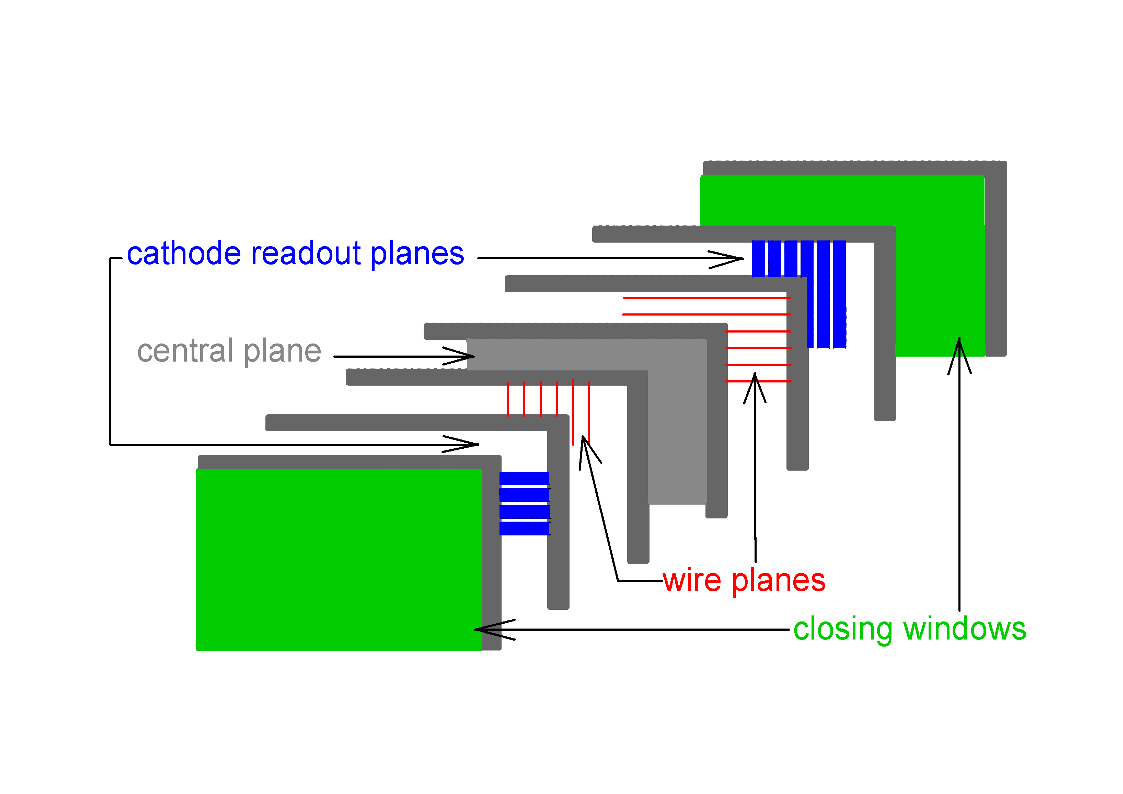
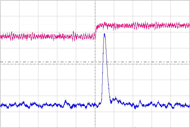
The positions of the incoming beam particles in the transverse plane are measured by a telescope of three Beam Position Detectors (BPDs) placed along the beamline upstream of the target. The NA61/SHINE BPDs (see Fig. 9 (left)) with active areas of were constructed in 2009. These detectors are proportional chambers operated with Ar/CO2 85/15 gas mixture. Two orthogonal sense wire planes (15 m tungsten wires with 2 mm pitch) are sandwiched between three cathode planes made of 25 m aluminized Mylar. The outer cathode planes of these detectors are sliced into strips of 2 mm pitch which are connected to the readout electronics. In order to detect beam particles at high intensities (about particles/second) shapers based on AD817 integrated amplifiers were constructed. The width of their output signal is about 350 ns. Negative undershoots of output signals observed with the NA49 shapers are practically eliminated (see Fig. 9 (right)).
Each BPD measures the position of the trigger-selected beam particle in two orthogonal directions independently using two planes of orthogonal strips. On each strip plane a charge distribution is induced with a width of about 5 strips on average. The reconstruction algorithm first searches for a cluster in each plane. The cluster is defined as a set of adjacent strips with signal amplitudes above a threshold value (to remove signals from pedestal fluctuations). Then, an average of the strip positions weighted with the signal amplitudes on the strips is calculated for the cluster to estimate the position of the beam particle (the so-called centroid method). A 3-dimensional point measured by a given BPD is built from two transverse coordinates measured by the two strip planes and the position of the BPD along the beamline.
In order to reconstruct a beam particle track, least squares fits of straight lines are performed to the positions measured by the three BPDs in and planes independently. Distributions of residuals associated with those fits are shown in Fig. 10. The RMS widths of the distributions indicate the order of magnitude of the accuracy of the BPD measurements, which is in agreement with the design value of 100 m. Differences of the RMS widths are mainly due to non-equal distances between the detectors in the direction ((BPD-1, BPD-2) = 21 m, (BPD-2, BPD-3) = 8 m).

3.4 Z-detectors
In order to select secondary ions by their charge at the trigger level, two Cherenkov counters (Z-detectors) were constructed. These are:
-
(i)
The Quartz Detector (QD) with a quartz (GE214P) plate as the radiator is equipped with two photomultipliers (X2020Q) attached to both sides of the quartz plate. Optical grease (BC630) is applied between the PMTs and the quartz plate in order to achieve good light transmission.
-
(ii)
The Gas Detector (GD) uses a 60 cm long C4F10 gas radiator. The construction of this detector is based on the standard CERN threshold Cherenkov unit. Cherenkov photons are reflected by a 25 m thick aluminized Mylar foil and focused by a parabolic mirror onto a single photomultiplier, Hamamatsu R2059.
The large refraction index of the quartz radiator of about 1.458 leads to a low Cherenkov threshold momentum of 0.88 per nucleon. Thus the detector performance is largely independent of the beam momentum in the momentum range relevant for the NA61/SHINE energy scan program. The refraction index of the C4F10 gas at normal conditions is about 1.00142 leading to a Cherenkov threshold momentum of about 17.6 per nucleon. For the momentum of 13 the lowest acceptable value of the refraction index is requiring a minimum gas pressure of 1.63 bar.
Both detectors were tested during the 2011 run using the secondary ion beam at 150 . The ADC signals measured in the Quartz and Gas Detectors showed well separated peaks of proton and He beam particles. Both detectors performed well at this momentum, namely the measured width to mean value ratio for the 4He peak was 18-19%. However, it was estimated that at the lowest beam momentum the performance of the GD will deteriorate both in terms of the charge resolution and the material budget (at the sufficiently high gas pressure it is about a factor of 2.5 larger than for the QD). Therefore the QD was used as the Z-detector for the physics data taking with secondary 7Be beams in 2011-2013.
Figure 5 presents distributions measured by the QD for secondary ion beams of 13, and 150 momentum used in the data taking on 7Be+9Be interactions.
3.5 Trigger system
In designing the NA61/SHINE trigger system, particular attention was paid to developing a flexible and robust system capable of handling and selecting different reactions using a variety of beams (pions, kaons, protons, ions) and targets as required by the NA61/SHINE physics programme [1].
The trigger is formed using several of the beam counters listed in Table 1, the Cherenkov detectors for beam particle (hadrons or ions) identification, and the PSD calorimeter, as illustrated in Fig 8.
The core of the trigger logic is an FPGA (Xilinx XC3s1500) running at 120 MHz embedded in a CAMAC Universal Logic Module, the CMC206 [22]. CAMAC is used for backward compatibility with the legacy NA49 electronics. The trigger logic is divided into three main blocks:
-
(i)
beam logic
-
(ii)
beam particle identification
-
(iii)
interaction logic.
Up to four different triggers can be run simultaneously with a selectable 12 bit pre-scaler for each trigger. Different trigger configurations are recorded in a pattern unit on an event-by-event basis for off-line selection.
Analog signals from the beam counters are first discriminated with constant fraction and leading edge discriminators before entering a second discriminator, whose role is to shape the logic signals (12 ns width) and convert them to ECL levels, as required by the FPGA trigger logic. These logic signals are also recorded in pattern units on an event-by-event basis for verifying the trigger logic in the analysis of trigger data. The combined use of two discriminators with different output widths prevents also the pile-up in the trigger logic (the length of the output of the first discriminator is around 100 ns, while the length of the second discriminator is 12 ns). Correspondingly, the dead time of the trigger system is around 100 ns, small compared to the dead time gated trigger rate of 100 Hz.
The simultaneous use of the beam () and interaction triggers () allows for the direct determination of the interaction probability, :
where is the number of events which satisfy the beam trigger condition and is the number of events which satisfy both the beam trigger and interaction trigger conditions.
4 TPC tracking system
The main tracking devices of the NA61/SHINE experiment are four large volume Time Projection Chambers (TPC). Two of them (Vertex TPCs: VTPC-1 and VTPC-2) are located in the magnetic field, two others (Main TPCs: MTPC-L and MTPC-R) are positioned downstream of the magnets symmetrically to the beamline. In addition a smaller TPC (GAP-TPC) is mounted between the two VTPCs. It is centered on the beamline for measuring particles with the smallest production angles. Also the Low Momentum Particle Detector presented in Sec. 7.2 consist of two small TPC chambers. The TPCs allow reconstruction of over 1000 tracks in a single Pb+Pb interaction. Up to 234 clusters and samples of energy loss per particle trajectory provide high statistics for precise measurements.
The TPCs consist of a large gas volume in which particles leave a trail of ionization electrons. A uniform vertical electric field is established by a surrounding field cage made of aluminized Mylar strips that are kept at the appropriate electric potential by a voltage divider chain. The electrons drift with constant velocity under the influence of the field towards the top plate where their position, arrival time, and total number are measured with proportional wire chambers. In order to achieve high spatial resolution the chamber top plates are subdivided into pads of about one square centimeter area, a total of about 180 000 for all TPC’s. From the recorded arrival times of the track signals and the known pixel positions one gets a sequence of 3-dimensional measured points along the particle trajectories.
An overview of the main parameters of the different TPCs is given in Table 2.
| VTPC-1 | VTPC-2 | MTPC-L/R | GAP-TPC | |
| size (LWH) [cm] | 250 200 98 | 250 200 98 | 390 390 180 | 30 81.5 70 |
| No. of pads/TPC | 26 886 | 27 648 | 63 360 | 672 |
| Pad size [mm] | 3.5 28(16) | 3.5 28 | 3.6 40, 5.5 40 | 4 28 |
| Drift length [cm] | 66.60 | 66.60 | 111.74 | 58.97 |
| Drift velocity [cm/s] | 1.4 | 1.4 | 2.3 | 1.3 |
| Drift field [V/cm] | 195 | 195 | 170 | 173 |
| Drift voltage [kV] | 13 | 13 | 19 | 10.2 |
| gas mixture | Ar/CO2 (90/10) | Ar/CO2 (90/10) | Ar/CO2 (95/5) | Ar/CO2 (90/10) |
| # of sectors | 2 3 | 2 3 | 5 5 | 1 |
| # of padrows | 72 | 72 | 90 | 7 |
| # of pads/padrow | 192 | 192 | 192, 128 | 96 |
4.1 VTPC, MTPC and GAP-TPC
Each Main TPC has a readout surface at the top of and a height of the field cage of about 1.1 m. It is filled with a gas mixture of Ar/CO2 in the proportion 95/5. The track signals are read out by 25 proportional chambers providing up to 90 measured points and ionization samples on each particle trajectory. The accuracy of the measurement of the average ionization energy loss for a particle is about 4%.
Each Vertex TPC consists of a gas box with top surface area and 0.67 m depth. The inserted field-cage structures exclude the region of 0.12 m on either side of the beamline in which the particle density in Pb+Pb reactions is so high that trajectories cannot be resolved. A gas mixture of Ar/CO2 in the proportion 90/10 is employed. The readout is performed by 6 proportional chambers on the top which provide up to 72 measurements and ionization samples on the particle trajectories. More details about the Vertex and Main TPCs can be found in Ref. [23].
Between VTPC-1 and VTPC-2 an additional tracking device, the GAP-TPC [24], is located directly on the beamline. It covers the gap left for the beam between the sensitive volumes of the VTPCs and MTPCs. High momentum tracks can be better extrapolated back to the primary vertex using the additional points measured in the GAP-TPC. Particles originating from the primary vertex but measured only in the MTPCs can be better distinguished from conversion electrons faking high momentum tracks outside the magnetic field. Since the beam passes through this detector its material budget was minimized to 0.15% of a radiation length and 0.05% of an interaction length. The design follows that of the other TPCs described above (the schematic layout is shown in Fig. 11). The electric field in the drift volume is generated by a field cage made from aluminized Mylar strips connected by a resistor chain. The electric field is 10.2 kV over 58.97 cm (173 V/cm) with a resulting drift time of about s. The support of the Mylar strips is provided by tubes of glass-epoxy with a wall thickness of m. The drift volume is enclosed by a gas box made of a single layer of m Mylar. The readout plane consists of 7 padrows with 96 pads each, the pad dimensions are 28 mm by 4 mm. The gas composition is Ar/CO2 (90/10) like in the VTPCs. For the readout three standard TPC front end cards are used together with one concentrator board.

4.2 He beam pipes
He filled beam pipes were installed in April 2011 in the gas volume of the VTPCs in order to reduce the number of -electrons by a factor of about 10. This is needed in order to decrease significantly event-by-event fluctuations of the track density in the TPCs and thus reduce systematic uncertainties of fluctuation measurements in nucleus-nucleus collisions. Installation of the pipes necessitated cutting openings in the double wall Mylar envelopes of VTPC-1 and VTPC-2. The openings were drilled using specially developed tools which prevented dust and debris of material from getting into the inner volume of the TPCs. These openings into the gas volume were precisely positioned around the beam axis and were used for gluing the lightweight interface units (m wall thickness carbon fiber rings) providing support for the He beam pipes and ensuring hermetic VTPC volumes. The lightest possible He beam pipe structure was produced that is feasible with present technology. The close-to-normal gas pressure conditions allow to use thin (m) gas-leakage-tight Tedlar polyvinyl fluoride (PVF) film [25] to produce 2.5 m length cylinder envelopes (pipes of 75 and 96 mm diameters), which form the He gas and protective gas volumes. The pipes were made by gluing the Tedlar film to special rigid, light-weight carbon fiber endcaps strengthened with Airex foam [26]. This provides low-mass beam pipe fixation, separation of gases and hermetic sealing. Use of light-weight low- materials minimizes the probability of secondary interaction processes. The used materials [25, 27, 26] include:
-
(i)
Tedlar polyvinyl fluoride (PVF) film
-
(ii)
Carbon Fiber M55J, g/cm3, cm
-
(iii)
Toray and
-
(iv)
Airex foam, = 0.03 g/cm3, = 1390 cm.
The construction is gas tight allowing separation of the working gas of the VTPCs from the helium used in the central pipe. In addition, during the operation an inert gas (CO2) is flushed through the outer envelope of the pipe (the protective gas volume). The He beam pipe installed in the VTPC-1, with gas supply lines connected, is shown in Fig. 12. A special gas supply system was constructed to maintain the overpressure gradients in the two gas volumes of the pipes with respect to the pressure in the VTPCs. This is mandatory to ensure the mechanical stability of the pipes. The He pipes were tested under working conditions of the VTPCs. They showed good mechanical stability when operating different modes of gas circulation in the VTPCs. No leakage of helium from the central pipes to the outer envelope was observed. The surface of the pipes did not show any excessive charging-up which could distort the drift field in the active VTPC volume. Gas tightness of the fixations of the pipes to the Mylar foils closing the VTPC field cage was tested by monitoring of the oxygen content in the VTPC gas. The oxygen contamination of the working gas decreased to a few ppms during the first 48 hours of purge (see Fig. 13) and remained constant at this level. The measured level of oxygen impurity after gas stabilization in the VTPCs was the same as that observed during the operation before the installation of the He beam pipes.
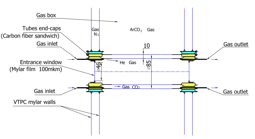
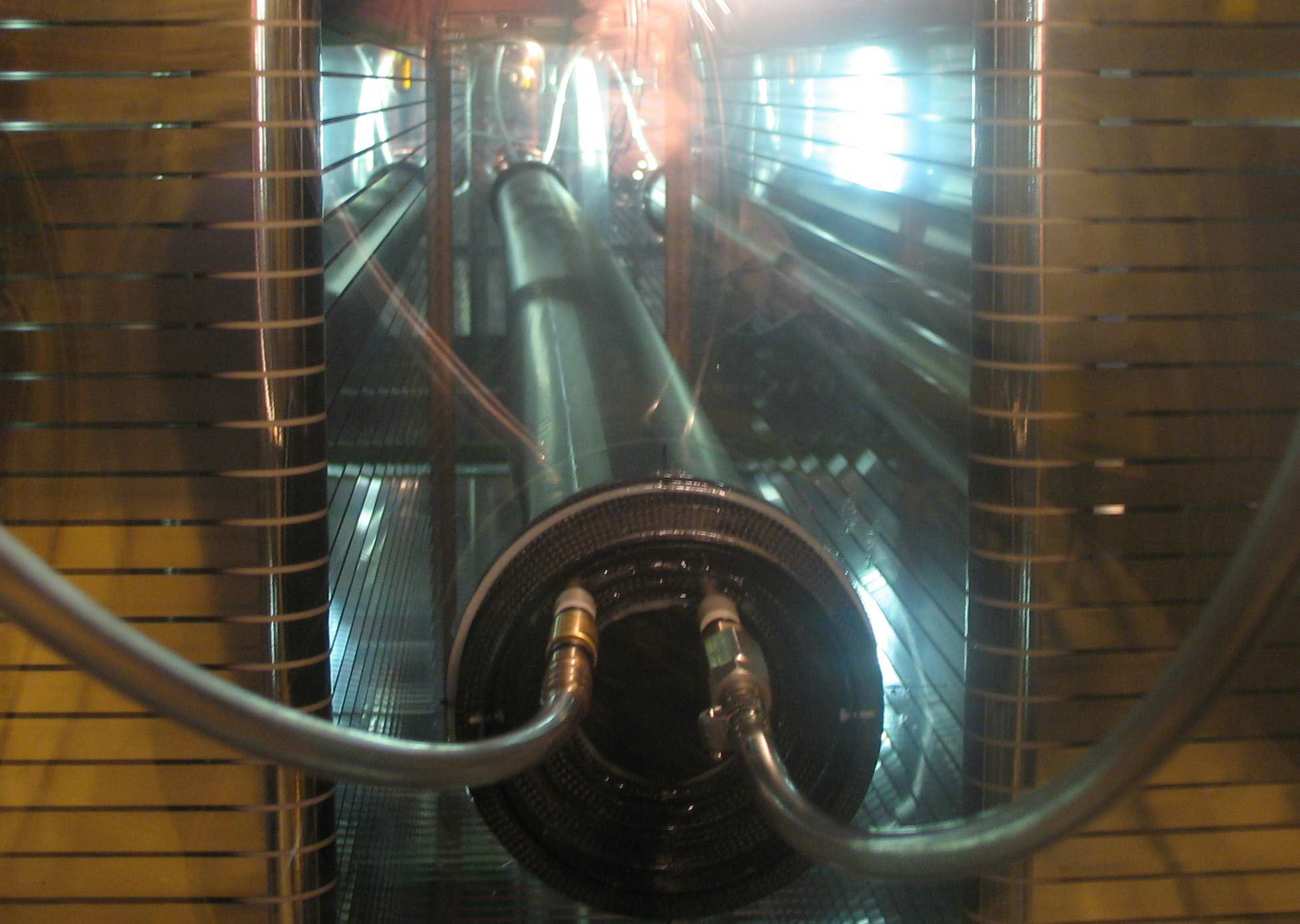

Figure 14 shows the interaction vertex distribution along the beam axis (data for p+p interactions at 158 ) before the He beam pipe installation (2009 and 2010 data) and with the He beam pipes installed and filled with helium gas (2011 data). Clearly, the He beam pipes reduce the number of background interactions in the volume of the VTPCs by about a factor of 10.

4.3 Magnets
The two identical super-conducting dipole magnets with a maximum total bending power of 9 Tm at currents of 5000 A have a width of 5700 mm and a length of 3600 mm. Their centers are approximately 2000 mm and 5800 mm downstream of the target. The shape of the magnet yokes is such that the opening in the bending plane is maximized at the downstream end. Inside the magnets a gap of 1000 mm between the upper and lower coils leaves room for the VTPCs. The coils have an iron-free central bore of 2 m diameter. This causes large field inhomogeneities where the minor components reach up to 60% of the central field at the extremities of the active TPC volumes. The magnetic field inside the sensitive volumes of the Vertex TPCs was precisely measured by Hall probes.
The standard configuration for data taking at beam momentum per nucleon of 150 and higher is nominally 1.5 T, in the first and 1.1 T in the second magnet. At lower beam momenta the fields are reduced proportional to the beam momentum keeping the ratio of the two fields constant. More details about the magnets can found in Ref. [23].
4.4 Gas system and monitoring

The gas in the VTPCs and MTPCs is supplied by four independent gas systems. A schematic drawing of one gas system is presented in Fig. 15.
Each system recirculates the gas with a compressor at a rate of about of the detector volume per hour, i.e. 0.9 and 3 m3/h for VTPCs and MTPCs, respectively. Fresh gas is mixed through mass flow controllers from pure Ar and CO2. In normal operation, the fresh gas is supplied at only detector volume per hour; in purge mode, the full recirculation rate is used. The recirculation flow is controlled by regulating the TPC overpressure to mbar via frequency modulation of the compressors.
Oxygen is cleaned from the detector gas by filter columns containing active Cu-granules chosen for use with the CO2 gas mixtures. The filters are regenerated after typically 4-6 months operation periods, using Ar/H2 (93/7) mixture at C. Fresh filters absorb water contamination in the gas for about 2 weeks, such that the water content may vary by 10 to 20 ppm.
Two bypass lines allow to start recirculation with the TPC isolated, and to replace the oxygen filter without stopping the system. In case of compressor failure a safety bubbler protects the TPC from overpressure.
The VTPC and MTPC walls are made of two layers of 125 m Mylar. Nitrogen is flushed between the layers, to prevent air from contaminating the TPC gas by diffusion through the walls, or a potential leak.
The monitoring of gas quality is one of the major tasks of the NA61/SHINE TPC gas system. Small amounts of gas can be directed to measuring units. Non-linearities and calibration drift of the flow controllers are followed by online measurements of drift velocity and gas amplification, as the required setting accuracy is beyond the specifications of the flow regulators. It is possible to measure the fresh gas mixture (point A in Fig. 15), and the gas from the TPC (point B). Each of the gas systems has a system of a drift velocity monitor and four gas amplitude monitors. Drift velocity is measured in a drift detector using the drift time difference from a pair of 241Am sources at 10 cm distance. The gas amplification is checked in the amplitude monitors. The amplitude monitors measure the signal from 55Fe photons in a proportional tube. The mixing and monitoring equipment is temperature stabilized to better than C.
Oxygen and water contamination in the TPC gas (point B), filtered gas (point C), and the input gas mixture (point D) can be measured with two pairs of O2/H2O sensors. Gas purities of 2–5 ppm oxygen and about 20–100 ppm water are typically achieved.
The gas circulation is typically started 1–2 weeks before the beginning of detector operation. First, the detector is flushed with fresh gas for 2 days in the purge mode. Due to limited precision of the input flow meters the gas mixtures needs several days to stabilize after purge. The drift velocity approaches a stable value exponentially with a time constant of approximately 28 hours for the VTPCs and 35 hours for the MTPCs (see Fig. 16).
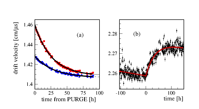
The drift velocity decreases by about 1% after purge which is attributed to out-gassing of the detector material. This is compensated by a slight increase of the argon content. Also, when the water contamination increases, the drift velocity decreases; the effect is of order of 1% for the typical water content of several tens of ppm. The change is slow (about 0.0002 cm/ per day) and is taken into account in the drift velocity calibration based on the online drift velocity measurements and more precise off-line drift velocity determinations.
The GAP-TPC with a volume of only about 150 l uses a much simpler gas system. About 20 l/h of fresh gas mixture is flushed through this detector. The gas coming out from the GAP-TPC is also passed through a drift velocity monitor.
The gas composition is Ar/CO2 90/10 in the VTPCs and GAP-TPC, and 95/5 in the MTPCs. The higher argon content in the MTPCs is required to obtain higher drift velocity necessary to read out the longer drift length (the safety limit on the drift high voltage is about 20 kV). Typical drift velocities are 1.4 cm/ in the VTPCs, 2.3 cm/ in the MTPCs and 1.3 cm/ in the GAP-TPC.
4.5 TPC Front End Electronics
The electron trace of the track ionization in the TPC gas drifts in the electric field to the amplification planes of the TPCs, which are operated in the proportional amplification range. After passing through the gating grid and the cathode grid, the drifted electrons get amplified by gas electron multiplication on the sense wires of the field and sense wire plane by about . The disappearance of this amplified electron signal on the sense wires capacitively induces an opposite-sign signal on the two-dimensionally segmented pad plane just behind the field and sense wire plane. Readout of the charge signal of the pads in consecutive short time intervals provides 3 dimensional information on the particle trajectories traversing the the TPCs. The electronic readout of the pads is performed by the TPC Front End Electronics (FEE).
One FEE channel is dedicated to each readout pad, pre-amplifies the signal and stores the analog charge of a given time sample in a capacitor array. 256 time slices with 200 ns time bins are used. It is also possible to use 512 time slices with 100 ns time bins. The time sampling is driven by a global clock for the full TPC system in order to eliminate relative phase shifts. 32 channels are handled by each FEE card, thus the full TPC system comprises about 6000 TPC FEE cards. After the analog charges are stored in the capacitor arrays their digitization is performed via a Wilkinson ADC on the card, and the digitized charge values are forwarded to the readout electronics.
4.6 Physics performance
Several examples of the physics performance of the TPC system are presented in this section, which were obtained from calibrated data. Details on the calibration procedure can be found in Ref. [30].
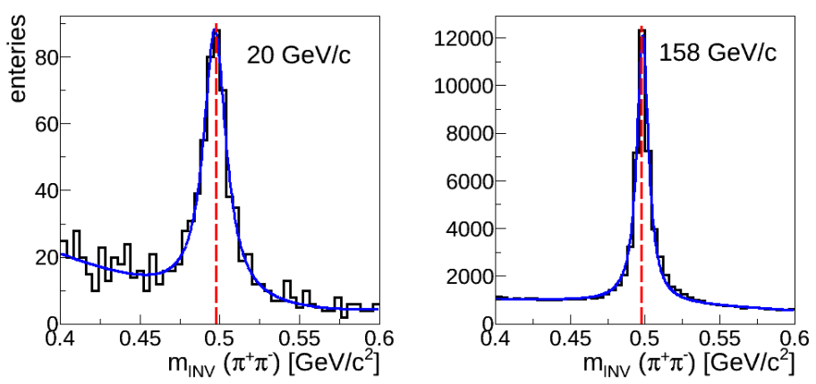
The quality of measurements was studied by reconstructing masses of particles from their decay topology. As an example the invariant mass distributions of candidates found in p+p interactions at 20 and 158 are plotted in Fig. 17. The measured peak positions 496.80.6 and 498.30.1 MeV/ are in reasonable agreement with the PDG value MeV/.
The track reconstruction efficiency and resolution of kinematic quantities were studied using a simulation of the detector. Estimates were obtained by matching of generated tracks to their reconstructed partners. As examples, the reconstruction efficiency as a function of rapidity and transverse momentum for negatively charged pions produced in p+p interactions at 20 and 158 is shown in Fig. 18. The measuring resolution of pion rapidity and transverse momentum is illustrated in Fig. 19. The resolution was calculated as the FWHM of the distribution of the difference between the generated and reconstructed and . Results presented in Figs. 18 and 19 were obtained for negatively charged pions passing the event and track selection criteria used in the data analysis [31], including rejection of the azimuthal angle regions where the reconstruction efficiency drops below 90%.


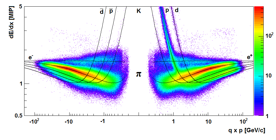
The specific energy loss in the TPCs for positively (right) and negatively (left) charged particles as a function of momentum measured for p+p interactions at 80 is shown in Fig. 20. Curves show parametrizations of the mean calculated for different particle species.
5 Time of Flight systems
Since particle identification based only on energy loss measurement can not be performed in the crossover region of the Bethe-Bloch curves, NA61/SHINE also uses additional and independent particle identification by Time of Flight (ToF) detectors. The ToF-L and ToF-R detectors were inherited from NA49. In order to extend the identification of NA61/SHINE to satisfy neutrino physics needs, a new forward detector (ToF-F) was constructed. It is placed between the ToF-L/R, just behind the MTPCs.
The particle’s mass squared is obtained by combining the information from the particle’s time of flight, , with the track length, , and momentum, , measured in the TPCs:
| (1) |
5.1 ToF-L, ToF-R
Two walls, ToF-L(eft) and ToF-R(ight), of 4.4 m2 total surface (see Fig. 21) are placed behind the MTPCs. The track length of particles produced in the target is about 14 meters. Each wall contains 891 individual scintillation detectors with rectangular dimensions, each having a single photomultiplier tube glued to the short side. The scintillators have a thickness of 23 mm matched to the photocathode diameter, a height of 34 mm and horizontal width of 60, 70 or 80 mm, with the shortest scintillators positioned closest to the beamline and the longest on the far end. The operating voltage for the PMTs in the ToF-L is about 1600 V and in the ToF-R is around 1300 V. For the ToF-L, photomultiplier signals enter constant-fraction discriminator modules (CFD, KFKI custom made), housed in VME crates (WIENER) where the analog signals are split before being passed through the actual discriminator units. One output signal is directly sent to FASTBUS analog-to-digital converters (96 channel ADC LeCroy 1885F) while the other signal passes first through the discriminator unit and is then sent to time-to-digital converters (64 channel FASTBUS TDC LeCroy 1775A). For ToF-R the PMT signals are first split, then one line is sent to an ADC (96 channel ADC LeCroy 1882F) while the other line goes into a FASTBUS CFD (Struck DIS Str138) followed by a TDC (64 channel FASTBUS TDC LeCroy 1772A). The start signal for the TDCs is provided by the S11 PMT of the upstream S1 beam counter (scintillator) while the stop signal comes from the CFDs if their input is above a threshold.
The calibration procedure is based on extrapolation of the tracks reconstructed in the MTPCs into the area of the ToF detectors, identifying scintillators they extrapolate to and checking for appropriate signals in the corresponding TDC and ADC channels. Afterwards detailed corrections are performed depending on charge deposition and relative position of the incident particle in each scintillator. Corrections for the position of the main interaction (in case of thick targets) and position of the beam particle in the S1 counter are also done.

The overall time resolution of the ToF-L/R system is estimated based on the distribution of the differences between the measured time of flight for particles identified as pions and that predicted from the measured momentum and trajectory assuming the pion mass. The distribution can be described by a Gaussian where, in p+p and Be+Be collisions, a standard deviation of 95 ps was observed for ToF-L, while a standard deviation of 80 ps was observed for ToF-R. This value for the time resolution includes all contributions to the measurement (the intrinsic ToF detector resolution as well as the start detector resolution, uncertainties in tracking, etc.).
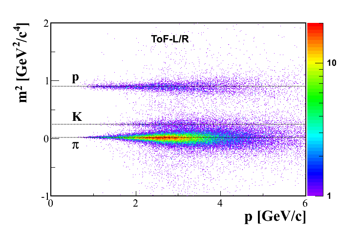
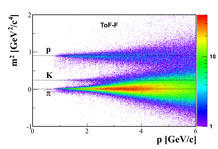
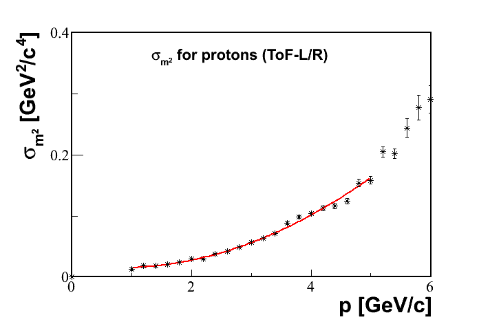
This resolution allows to separate pions and kaons for momenta up to 3 (up to 5 if information is used along with information) and pions and protons for even higher momenta. Figure 22 () shows mass squared as a function of particle momentum for p+p interactions at 80 . The resulting resolution in is plotted as a function of momentum in Fig. 22 ().
Due to aging of the electronics two upgrades are foreseen. The HV supply will be partially replaced and an upgrade of the readout electronics is planned. This should, modernize the whole system, ensure its long-term functioning, and also improve the quality of the obtained information, primarily the resolution.
5.2 ToF-F
The NA61/SHINE data taking for the T2K neutrino oscillation experiment requires particle identification in a phase space region which is not covered by the ToF-L/R. When operating at the T2K proton beam at 31 , a large fraction of the tracks are produced by low-momentum particles which exit the spectrometer between the ToF-L and ToF-R. An additional time of flight detector, the forward ToF (ToF-F), was therefore constructed to provide full time of flight coverage of the downstream end of the MTPCs (see Fig. 1).
The ToF-F consists of 80 scintillator bars oriented vertically (see Fig. 23). The bars were tested and mounted in groups of 10 on independent frames (modules) out of which half were placed on the left side and half on the right side of the detector. The size of each scintillator is 120102.5 cm3. They are staggered with 1 cm overlap to ensure full coverage in the ToF-F geometrical acceptance. This configuration provides a total active area of 720120 cm2. Each scintillator bar is read out on both sides with photomultipliers Fast-Hamamatsu R1828, for a total of 160 readout channels. The scintillators are plastic scintillator (Bicron BC-408) with a scintillation rise time of 0.9 ns, a decay time of 2.1 ns and attenuation length of 210 cm. Their maximal emission wavelength is about 400 nm perfectly matching the PMT spectral response. Fish tail PMMA (Poly methyl methacrylate) light-guides were glued on both ends for the readout. The bars and light-guides were wrapped in aluminium foils to ensure light reflection towards the light-guide and covered with black plastic foils and tape. In order to ensure proper optical contact between the PMTs and the light-guides a 3 mm thick silicone cylinder matching the diameter of the PMT and light-guide is inserted at the interface.

Most of the electronics for the ToF-F were inherited from the two NA49 Grid ToFs [32] which were not used since their acceptance coverage is marginal. Each PMT channel is operated near 1700 V supplied by LeCroy1461 independent 12-channel high voltage (HV) cards. The analog signals are transported from the ToF to the counting house by 26 m RG58 50 coaxial cables. In order to obtain fast logic signals and not be influenced by the variations in amplitude of the PMT response the cables are plugged into Constant Fraction Discriminators (16-channel KFKI CFD5.05 VME module). At the input these include an internal passive divider of 1:3 to provide the signals for the integrated charge and time measurements, respectively, and the necessary delay lines at their output. In order to minimize the crosstalk of the neighboring channels an appropriate order is chosen between the PMT outputs and the CFD inputs. The output signals of the CFDs of the PMT-channels serve as “stop” signals for the time of flight measurements. The start signal is provided by the fast beam counter S1 of the central trigger system. The time measurement is carried out by LeCroy FASTBUS Time-to-Digital Converter (TDC) units digitizing the time in 12 bits dynamic range with a sampling time of 25 ps. The analog signals of the PMTs are converted by LeCroy Analog-to-Digital Converter (ADC) units into 12 bits. The time measurement, , has an offset, , which is specific to each channel as it depends on cable length, PMT gain or CFD response. was therefore carefully adjusted on a channel by channel basis by first assuming that all produced particles are pions and shifting the mean value of the distribution accordingly. In a first iteration, this method allows to discriminate pions from protons and was then repeated by selecting only pions.
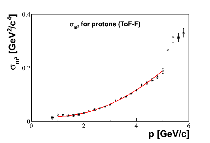
The mass-squared distribution and the resolution of its measurement as a function of momentum are presented in Fig. 22 (). The intrinsic resolution of the ToF-F was also determined (see Fig. 24). This was achieved by selecting particles that hit the region where the scintillators overlap and plotting the time difference between the two signals. The Gaussian fit to the distribution gives a resolution ps.

6 Projectile Spectator Detector
The development and construction of the forward hadron calorimeter was one of the most important upgrades of the NA61/SHINE experimental setup. This calorimeter is called the Projectile Spectator Detector (PSD). The purpose of the calorimeter is the measurement of projectile spectator energy in nucleus-nucleus collisions. The PSD is used to select central (with a small number of projectile spectators) collisions at the trigger level. Moreover, the precise event-by-event measurement of the energy carried by projectile spectators enables the extraction of the number of interacting nucleons from the projectile with the precision of one nucleon. The high energy resolution of the PSD is important for the study of fluctuations in nucleus-nucleus collisions which are expected to be sensitive to properties of the phase transition between the quark-gluon plasma and hadron-resonance matter. Namely, the PSD provides the precise control over fluctuations caused by the variation of the number of interacting nucleons and thus excludes the "trivial" fluctuations caused by variation of the collision geometry. Basic design requirements of the PSD are good energy resolution,, and good transverse uniformity of this resolution. The PSD is a fully compensating modular lead/scintillator hadron calorimeter [33, 34] and meets these requirements.
6.1 Calorimeter design
The PSD calorimeter consists of 44 modules which cover a transverse area of 120x120 cm2. A schematic front view of the PSD is shown in Fig. 25 (left). The central part of the PSD consists of 16 small modules with transverse dimension of 10x10 cm2 and weight of 120 kg each. Such fine transverse segmentation decreases the spectator occupancy in one module and improves the reconstruction of the reaction plane. The outer part of the PSD consists of 28 large 20x20 cm2 modules with a weight of 500 kg each.

Each module, schematically shown in Fig. 25 (), consists of 60 pairs of alternating lead plates and scintillator tiles with 16 mm and 4 mm thickness, respectively. The stack of plates is tied together with 0.5 mm thick steel tape and placed in a box made of 0.5 mm thick steel. Steel tape and box are spot-welded together providing appropriate mechanical rigidity. The full length of the modules corresponds to 5.7 nuclear interaction lengths.
Light readout is provided by Kyraray Y11 WLS-fibers embedded in round grooves in the scintillator plates. The WLS-fibers from each longitudinal section of 6 consecutive scintillator tiles are collected together in a single optical connector at the end of the module. Each of the 10 optical connectors at the downstream face of the module is read out by a single photodiode. The longitudinal segmentation into 10 sections ensures good uniformity of light collection along the module and delivers information on the type of particle which caused the observed particle shower. Ten photodetectors per module are placed at the rear side of the module together with the front end electronics. A photograph of the fully assembled calorimeter is shown in Fig. 25 (right). In order to fit the PSD transverse dimensions to the region populated by spectators the distance between the NA61/SHINE target and the calorimeter is increased from 17 m to 23 m with increasing collision energy. Interactions of spectators upstream of the PSD were minimized by the installation of a helium tube of length 5.5 m and diameter 125 cm between the upstream PSD face and the hut housing the MTPCs. The entrance and exit Mylar windows of the tube had a thickness of about 125 m. This tube was inserted for data taking with ion beams of momenta larger than 40 when the distance between the target and the PSD was 23 m.
6.2 PSD photodetectors
The longitudinal segmentation of the calorimeter modules requires 10 individual photodetectors per module for the signal readout. Silicon photomultipliers SiPMs or micro-pixel avalanche photodiodes, MAPDs [35, 36] are an optimum choice due to their remarkable properties such as high internal gain, compactness, low cost and immunity to the nuclear counter effect. Moreover, forward hadron calorimeter applications have some specific requirements such as large dynamic range and linearity of the photodetector response to intense light pulses. However, the dynamic range and linearity of MAPDs are limited by the finite number of pixels. Most of the existing types of MAPD with individual surface resistors have a pixel density of pixels/mm2. Such a limited number leads to serious restrictions of MAPD applications in calorimetry, where the number of detected photons is comparable and even larger than the pixel number. The effect of saturation, when a few photons hit the same pixel, leads to significant non-linear MAPD response to light pulses with high intensity. Evidently, the MAPD has linear response only if the number of pixels is much larger than the number of incident photons. This feature represents a disadvantage of MAPDs compared to the traditional PMTs. However, this drawback is essentially reduced for MAPDs with individual micro-well structure [35], for which a pixel density of 104/mm2 and higher is achievable. The above considerations motivated the choice of photodiodes of type MAPD-3A produced by Zecotek Photonics Inc. (Singapore) [36] for the readout of the PSD hadron calorimeter. These MAPDs have a pixel density of 15000/mm2. Their 3x3 mm2 active area fits well the size of the WLS-fiber bunch from one longitudinal section of the PSD modules and provides a total number of pixels of more than 105 in a single photodetector.
The MAPD-3A photon detection efficiency (PDE) for the Y11 WLS-fiber emission spectrum reaches 15% at 510 nm and is similar to the performance of PMTs. The operation voltage for different samples of MAPD-3A detectors ranges from 65 V to 68 V. The maximum achieved gain is 4104, see Fig. 26 (left).

Since the PSD calorimeter has no beam hole to ensure maximum acceptance for the spectators, the central part of the PSD is exposed to ion beams with intensities up to 105 Hz. The average amplitude in one longitudinal section of a PSD module is expected to be about 1500 photoelectrons. Therefore, an important requirement for the calorimeter readout is a high count rate capability, at least in the central region. In particular, the recovery time of the selected MAPD-3A photodiode must be fast enough to deliver stable amplitudes at signal frequencies up to 105 Hz. To check the count rate capability of the MAPD-3A the dependence of its amplitude on the frequency of light pulses was measured. The stability of the amplitude of the pulses at different operation frequencies of the light emitting diode was checked by a normal PMT. The obtained behavior of the amplitude produced by the MAPD-3A is presented in Fig. 26 (). As seen, the MAPD-3A amplitude would drop about 5% for the maximum beam intensity foreseen.
In order to check the photodetector linearity, measurements of MAPD amplitudes were performed with light pulses of different intensity. The number of incident photons was determined by a reference photodiode with known quantum efficiency and gain equal to one. The dependence of the MAPD amplitude on the number of incident photons is shown in Fig. 26 (right). As seen, the MAPD linearity is preserved for light pulses with number of photons up to 6104. Taking into account the different photon detection efficiencies of about 25% for the tested MAPD (with the same pixel density as the MAPD-3A type) and 15% for the MAPD-3A, linear response is expected for amplitudes up to 15000 photoelectrons.
The reported comprehensive studies confirm that the selected MAPD-3A photodetectors satisfy the requirements of the NA61/SHINE experiment. At present, 440 MAPD-3A detectors are installed in the 44 PSD modules and show stable operation during data taking for calibration and physics with beryllium and proton beams.
6.3 Performance of the PSD calorimeter
In order to check the performance of the calorimeter, several tests were performed with hadron beams of various momenta. During the first stage of the R&D (in 2007) a PSD module array of nine small modules (33 array) was assembled and tested in the H2 beamline using hadron beams of 20-158 momentum. The calibration of all readout channels was done with a muon beam. The energy resolution of the tested array was estimated from data taken with the hadron beams.
The dependence of the measured energy resolution on the pion energy is shown in Fig. 27 (left).
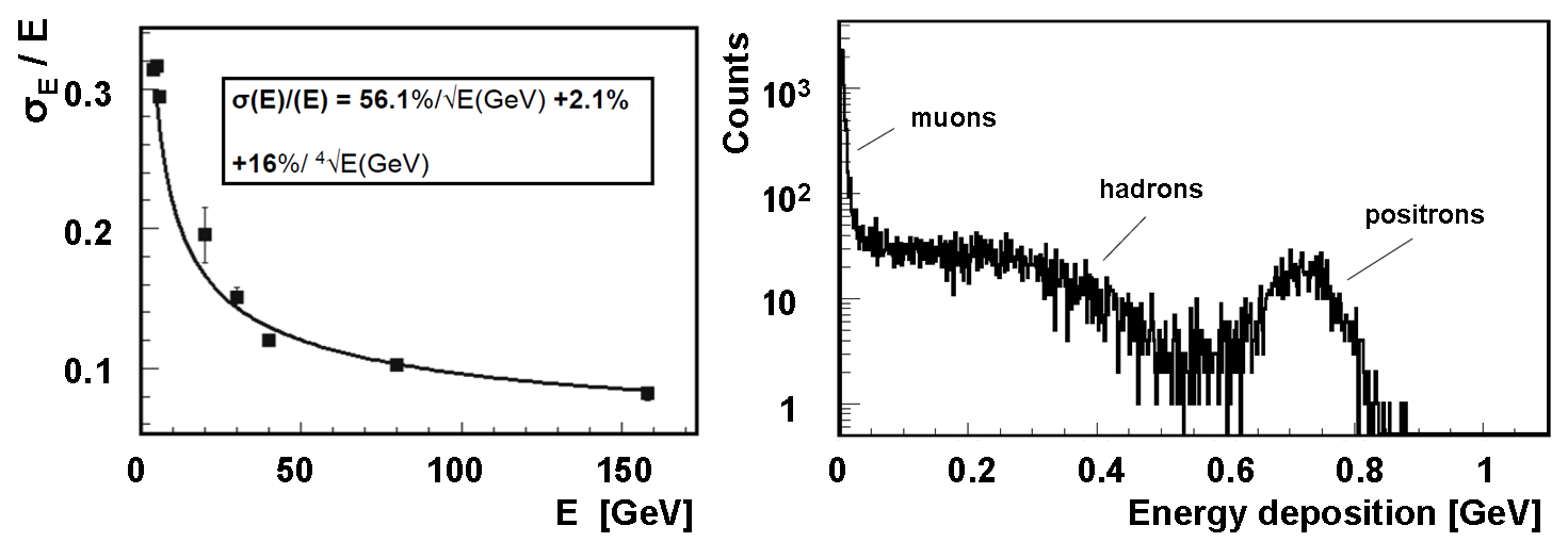
The tested prototype with 3030 cm2 transverse size is too small to contain the entire hadron shower. Therefore, a non-negligible lateral shower leakage is expected. Monte Carlo simulations confirm that about 16% of the hadron shower energy escapes from the tested array. The influence of shower leakage on the energy resolution was studied in Refs. [37, 38], where a third term in addition to the stochastic and constant terms was added in the parameterization of the resolution. The fit of the experimental data with the three-term formula, assuming a fixed leakage term of 16%, gives the coefficient of the stochastic term equal to 56.1% and of the constant term equal to 2.1%. The non-zero constant term might be an indication that the selected lead/scintillator sampling does not provide full compensation.
The spectrum of deposited energy in the first section of the central module exposed to the 30 positively charged H2 beam is shown in Fig. 27 (right). The right-side peak in the spectrum corresponds to full positron energy absorption in the first longitudinal section which can be regarded as an electromagnetic calorimeter with coarse sampling. The energy resolution for positrons at 30 is about 6.5%.
During the 2011-2013 data taking for 7Be + 9Be collisions the PSD was also used in the trigger for online rejection of the most peripheral events. As a secondary 7Be beam was used other ions were also present in the beam. The distribution of the energy deposited in the calorimeter by 75 beam ions is shown in Fig. 28 (left) without cut (red) and with cut (blue) on the 7Be peak in the amplitude distribution of the Z-detector. Clear identification of 7Be ions in the fragmented beam is seen here as well as contamination of deuteron and helium ions. Figure 28 (right) shows the PSD energy spectra recorded during the data taking for 7Be+9Be collisions at 75 . Spectra are shown for the beam trigger (blue) and interaction trigger (red).
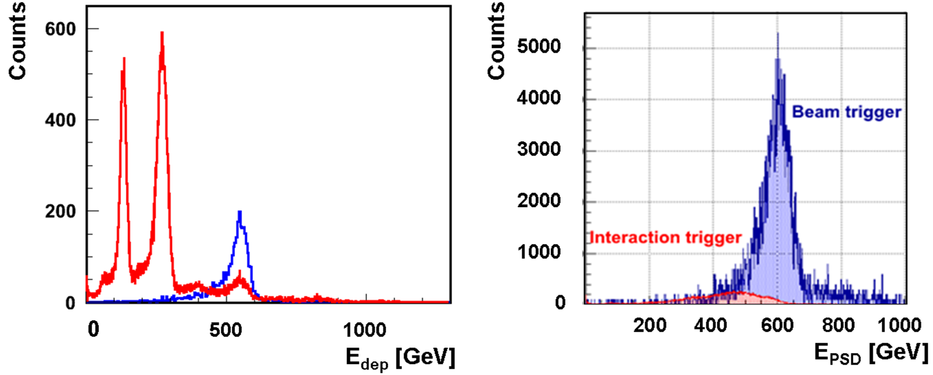
Figure 29 () shows the measured energy of 158 protons as a function of the module number on which the beam was centered. Histograms and curves in Fig. 29 () distinguish different energy reconstruction methods by color. Red corresponds to the energy sum of all PSD modules, while blue is for the sum of the corresponding clusters of modules around the beam spot. As seen, the mean values of reconstructed energies are close to the real beam energy in both cases.
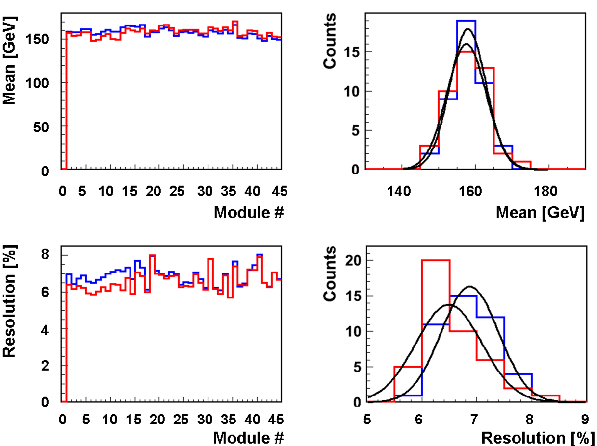
Figure 29 () presents the energy resolution obtained for each of the 44 modules from the scan with 158 protons. The small variations in the energy resolution can be explained by the precision of the energy calibration. These results are consistent with the prototype tests and with the MC simulations.
7 Targets and LMPD
The targets used by NA61/SHINE are positioned upstream of the VTPC-1 and centered at = -581 cm. In data taking on p+Pb interactions the target was sourounded by the LMPD detector.
7.1 Targets
For data taking on p+p interactions the liquid hydrogen target (LHT) of 20.29 cm length (2.8% interaction length) and 3 cm diameter was placed 88.4 cm upstream of the VTPC-1. The target was filled with para-hydrogen obtained in a closed-loop liquefaction system which was operated at 75 mbar overpressure with respect to the atmosphere. At the atmospheric pressure of 965 mbar the liquid hydrogen density is g/cm3. The boiling rate in the liquid hydrogen was not monitored during the data taking and thus the liquid hydrogen density is known only approximately. Data taking with inserted and removed liquid hydrogen in the LHT was alternated in order to calculate a data-based correction for interactions with material surrounding the liquid hydrogen. The density of gaseous hydrogen present in the target after removal of liquid hydrogen was estimated from the ratio of high multiplicity events observed in a small fiducial volume around the target center for data taken with inserted and removed liquid hydrogen. The density ratio varied within the range 0.4-0.6%. This indicates that the operational conditions of the LHT varied during the data-taking period.
For data taking on 7Be+9Be collisions in the period 2011-2013 two beryllium targets were used. Their density was = 1.85 g/cm3 at 20oC and dimensions were cm3 and cm3. The targets consisted of more than 99.4% 9Be. The most abundant contaminant were oxygen nuclei (about 0.4%). The Be targets were placed in an aluminium container filled with atmospheric pressure helium gas.
For data taking on p+Pb collisions a special thin Pb target disc was used in order to reduce in-target absorption of slow protons which mre easured by the LMPD and are used for event centrality tagging. Two different target thicknesses, 0.5 mm and 1 mm, were used to allow an experimental study of in-target absorption of slow protons. The transverse shape of the target was circular, with a diameter of 1 cm. The target material purity was 99.98% lead with natural isotope composition (52.4% Pb, 22.1% Pb, 24.1% Pb, 1.4% Pb). The target density was 11.34 g/cm3 at 20oC with a molar mass of 207.2 g/mol. The target disc was placed in a Tedlar [25] foil container filled with atmospheric pressure helium gas in order to reduce background of off-target collisions in the vicinity of the target. The target was removable from the beamline using a pneumatic piston for reference data taking with the target removed needed to estimate background due to off-target interactions.
For measurements at 158 and 350 a thin graphite target of dimensions cm3 and density = 1.84 g/cm3, placed in an aluminium container filled with helium gas, was employed by NA61/SHINE. The same target was used for hadro-production measurements of interest for the T2K neutrino oscillation experiment in Japan. In these measurements information about primary interactions of protons on carbon was extracted. The thickness of this target along the beam axis was equivalent to about 4% of a nuclear interaction length .
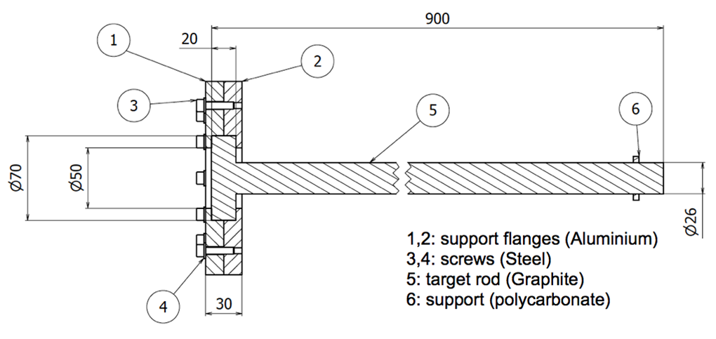
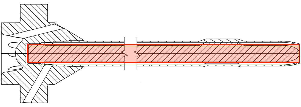
For hadro-production measurements also a thick graphite target, a replica of the T2K target, was used. It consists of a 90 cm long rod with a radius of 1.3 cm and a density of = 1.83 g/cm3. The replica and the actual target of T2K are shown in Fig. 30. The upstream part of the graphite target is surrounded by aluminium flanges which are inserted into a target holder. Three screws in the target holder allow to align the target parallel to the beam axis. The target thickness along the beam axis is equivalent to about 1.9 interaction lengths. The downstream face of the replica target was placed at around 50 cm from VTPC-1. Hadro-production measurements taken with the T2K replica target allow to constrain the contributions from primary and secondary interactions within the target (for details see [39]).
7.2 Low Momentum Particle Detector
In hadron-nucleus interactions the collision centrality can be deduced from the number of emitted low momentum protons (the so-called grey protons). For this purpose a special detector, the Low Momentum Particle Detector (LMPD), was constructed [44]. The detector consists of two small size TPC chambers on the two sides of the target with a vertical drift field, and a sequence of detection layers picking up the ionization signal of radially emitted particles. Between the detection layers plastic absorber layers are inserted. Therefore the range of particles in the detector material can be determined. The range and energy loss by ionization of a particle depends on its energy and type, and therefore event-by-event counting of the number of emitted low energy protons becomes possible. Prototypes of the detector were tested in 2009 and 2010.
The final version of the LMPD, see Fig. 31 along with Table 3, was manufactured in 2011, and was first tested in the NA61/SHINE experimental area, downstream of the NA61/SHINE detector, in parasitic mode. The tests showed the expected performance of the detector, namely its capability of proton identification and of counting the low energy (grey) protons. A typical raw event overlayed with the reconstructed clusters and tracks is seen in Fig. 32 (left). The ionization produced by particles with fixed range is shown in Fig. 32 (right). The signal of protons with a selected penetration range is clearly visible along with other fragment species such as helium nuclei. The cluster reconstruction uses a closest neighbor search algorithm, while the track reconstruction uses the Hough transform procedure combined with the maximum likelihood principle for pattern recognition. Figure 32 (bottom) shows the distributions of interaction vertex coordinates reconstructed from LMPD tracks for events recorded with inserted (red histograms) and removed target (blue histograms). The signal of events from interactions in the Pb target is clearly visible and the contribution from non-target interactions is small.


| LMPD | |
|---|---|
| size (LWH) [cm] | 29 x 15.5 x 22.5 |
| No. of pads/sector | 140 |
| Pad size [mm] | (4-9) x 6 |
| Drift length [cm] | 20.5 |
| Drift velocity [cm/s] | 0.9 |
| Drift field [V/cm] | 195 |
| Drift voltage [kV] | 4 |
| drift gas | Ar/CO2 (85/15) |
| # of sectors | 2 2 |
| # of padrows | 10 |
| # of pads/padrow | 8,8, 14,14, 16,16, 16,16, 16,16 |
| Absorber thickness [mm] | 0.5, 1.0, 2.0, 2.5 |
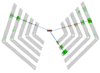


The operational parameters of the LMPD were optimized during the 2011 test. In particular, a gradual decrease of amplification in the layers close to the target was introduced. This is necessary in order to adjust the dynamic range for the expected highly ionizing particles. After optimization large statistics physics-quality data were recorded in parasitic mode with the LMPD located downstream of MTPCs. They allow a systematic study of gray proton production and absorption in the target material. During the last 3 days of the 2011 data taking period with proton beams, the LMPD was mounted at the nominal position, and preliminary physics-quality p+Pb data were recorded for the final test of the operational parameters. Then, in 2012 large statistics 158 p+Pb physics data were taken with the LMPD sourounding the target. This allows detection and tagging of grey protons and thus characterizing the centrality of the p+Pb collisions.
8 Data acquisition and detector control systems
8.1 Readout electronics and DAQ
The readout electronics [45] consists of three main parts: the electronics responsible for reading out the TPC FEEs, the electronics for reading out the FASTBUS based ToF system, and the electronics for reading out the CAMAC based beam detectors (see Fig. 33).

In case of the TPC system, the FEE cards [28, 29] only host pre-amplifiers, shapers, and time-sampling capacitor arrays for 32 channels, along with ADCs. The necessary command logic is managed by the readout Mother Boards, which transmit the necessary clock signals to steer the time sampling, ADC conversion and data transmission process. The FEE cards produce a 9 bit ADC value for each time slice of each TPC pad. These are pedestal subtracted, noise suppressed and zero compressed on the Mother Boards. The 250 Mother Boards, which are each capable of serving 24 FEE cards, were implemented using Cyclone II FPGA (EP2C35F672) arrays and SRAM units for pedestal table storage. Upon an event trigger, which is fanned out to all Mother Boards, the time sampling with subsequent digitization begins on the FEE cards, after which the ADC values are read out and processed on the fly by the Mother Boards with polling. The processed data stream is serialized onto a ground-independent LVDS connection line toward the Concentrator Boxes, which can receive data from 32 Mother Boards. These boxes act like further serializers and are implemented on Cyclone II FPGA (EP2C20F484) arrays. In order to ensure galvanic ground independence for the long-distance transfer, the DDL optical transfer line [40, 41] is used from this point to the Central DAQ PC. The data reaches the Central DAQ in push-data mode, i.e. the data stream is triggered by the lower level electronics and not via the Central DAQ. Upon the arrival of the first data headers at the Concentrator Box level, a Busy signal is issued as a feedback to the trigger electronics.
The ToF system uses legacy front end electronics based on FASTBUS technology. The readout of the beam-related detectors (Beam Position Detectors, beam counter pattern units, scalers, ADCs and TDCs) is based on traditional CAMAC units. A FASTBUS-to-VME bridge and a CAMAC-to-VME bridge, makes connection to VME crates dedicated to ToF and CAMAC readout, respectively. In each of these two VME crates a FIC8234 processor-based controller runs a low level OS9 based software as low level DAQ. As the processors are capable of receiving external signals as interrupt, the latter are used to initiate low level data taking. The measurement units are triggered by the experiment’s accurate pre-trigger signal, but the measurement data are only read out if this is confirmed by the main-trigger signal within the time-out limit. In that case an interrupt is passed to the FIC8234 controllers to initiate readout. The data are transfered via the bridges to a MM6390 memory unit in the VME crate. The received data are stored in a ring buffer overwriting older data and a trigger counter is incremented. Meanwhile the Central DAQ polls for the incrementation of the trigger counter, and the new events are drained via a CAEN V1718 VME-to-USB bridge to the Central DAQ’s ring buffer. Feedback to and control of the Busy logic is performed via RCB8047 CORBO register units in the pertinent VME crates.
The readout of the PSD, is designed along the principles of the TPC readout, and acts similarly to the Mother Boards in the TPC readout system.
Due to the push-data mode method, the event data in the different hardware channels arrive at the Central DAQ software asynchronously. The synchronization is performed via trigger counters in the sub-events on the final event-building level. For periodic checks the data stream is halted each minute, the data pipelines are drained and the trigger counter synchronicity is verified. In addition, the Busy signal of each hardware channel is monitored via a custom made galvanically isolated TTL to RS232 register in order to make sure that the event stream is never halted due to a stuck Busy signal caused by a hardware failure.
The Central DAQ software runs on a single Central DAQ PC (X7DB8-X motherboard, 64 bit, total 8 cores of Intel Xeon CPU @ 2 GHz, 8 GB memory, 10 PCI-X slots, 4 USB ports, and a serial port). The main components of the software and their functions are as follows:
-
(i)
The core software of the Central DAQ written in C. Its user interface is a command line interpreter written using the GNU libreadline library.
-
(ii)
The Central DAQ GUI script written in Tcl/Tk language.
-
(iii)
The event server, created upon Central DAQ start for event monitoring. This is a fork-server serving up to 16 monitoring clients.
-
(iv)
The following processes created upon run start:
-
(i)
The logger and monitoring / consistency checking process.
-
(ii)
The communication unit with the trigger system for summary information. This periodically gets scaler status information from the trigger server.
-
(iii)
The communication unit with the DCS system for summary information. This periodically gets information from the DCS server.
-
(iv)
The recorder process building the event, writing to disk and forwarding to the above event server upon request. This starts the following two processes for efficient parallelization of data receiving.
-
(i)
The receiver process for the DDL channels. This looks for data on any DDL channel on a first-come first-served basis.
-
(ii)
The receiver process for the VME channels. This looks for data on any VME channel on a first-come first-served basis.
-
(i)
-
(i)
The GUI and the command line interpreter communicate via standard Unix pipes and log files. The processes of the forked C program communicate via Linux shared memory. The data itself gets read into a special fast shared memory, called Physmem, outside the reach of the Linux kernel. Physmem is mapped by a special Linux kernel module shipped with the DDL libraries.
The central DAQ software is completed by a system of failure-tolerant scripts with checksum and size verification, which move the recorded data after consistency and Quality Assessment check onto the tape system of CASTOR.
8.2 Detector Control System
The NA61/SHINE Detector Control System (DCS) is responsible for online monitoring and controlling of the working conditions of the detectors.
The system monitors parameters of the gas mixture in the TPCs (temperatures, pressure, flow, water and oxygen content, drift velocity, amplification, etc.). It also sets and monitors parameters of the high voltage in the sub-detectors: LMPD, TPCs, BPDs and the beam counters. The system also controls low voltage power supplies of the front end electronics and enables its cooling.
The block diagram of the DCS is shown in Fig. 34.

Although the system logically consists of the following subsystems:
-
(i)
Gas subsystem,
-
(ii)
High Voltage subsystem,
-
(iii)
Low Voltage subsystem,
-
(iv)
PSD subsystem,
the main part of the system is a single EPICS-based [42] measurement server distributed over a few PCs. It communicates with various hardware (CAMAC, VME, PLC, etc.) via various interfaces (RS232, Caenet, TCP/IP, GPIB, etc.), performs all the measurements and makes the results accessible for the clients via the Channel Access protocol. The server runs constantly regardless of the presence of the clients or the database availability.
All measured data is stored in the relational database (PostgreSQL) by one of the EPICS clients. It can be accessed only via the Database Access Server by issuing ASCII commands.
There are two GUIs available. One of them, which controls the Measurement Server and monitors its performance, is an EPICS client and can be run only in the experimental area. The other one can be run anywhere and is graphically presenting results of measurements retrieved from the database.
9 Summary and outlook
NA61/SHINE (SPS Heavy Ion and Neutrino Experiment) is a multi-purpose facility for the study of hadron production in hadron-proton, hadron-nucleus and nucleus-nucleus collisions at the CERN Super Proton Synchrotron.
NA61/SHINE has greatly profited from the long development of the CERN proton and ion sources, the accelerator chain, as well as the H2 beamline of the CERN North Area. The latter has recently been modified to also serve as a fragment separator as needed to produce the Be beams for NA61/SHINE. Numerous components of the NA61/SHINE setup were inherited from its predecessors, in particular, the last one, the NA49 experiment.
This paper describes the facility - the beams and the detector system - as used up to March 2013, the start of the CERN Long Shutdown I. Special attention was paid to the presentation of the components which were constructed for NA61/SHINE. These are: the Projectile Spectator Detector, the Forward-ToF wall, the Low Momentum Particle Detector, the Z- and A-detectors, the Beam Position Detectors, the digital part of the TPC readout and the DAQ system, the Trigger System, the Detector Control System and the He-beam pipe. Moreover the upgraded CERN accelerator chain and the H2 beamline modified to serve as a fragment separator are described. The components inherited from the past experiments and described elsewhere are presented only briefly. These are the Time Projection Chambers and their gas system, the two super-conducting magnets, the ToF-L/R walls as well as the beam and trigger counters.
Upgrades of the facility are continuing and the physics goals are being expanded [43]. Among NA61/SHINE upgrades under preparation are: construction of Forward-TPCs and of a Silicon Vertex Detector, upgrade of the ToF and PSD readout systems, upgrade of the ToF HV system and extension of the gas system.
This paper will be followed by further publications presenting more details on the components which were newly constructed for the NA61/SHINE facility.
Acknowledgements: This work was supported by the Hungarian Scientific Research Fund (grants OTKA 68506 and 71989), the Polish Ministry of Science and Higher Education (grants 667/N-CERN/2010/0, NN 202 48 4339 and NN 202 23 1837), the National Science Center of Poland (grant UMO-2012/04/M/ST2/00816), the Federal Agency of Education of the Ministry of Education and Science of the Russian Federation (grant RNP 2.2.2.2.1547), the Russian Academy of Science and the Russian Foundation for Basic Research (grants 08-02-00018, 09-02-00664, and 12-02-91503-CERN), the Ministry of Education, Culture, Sports, Science and Technology, Japan, Grant-in-Aid for Scientific Research (grants 18071005, 19034011, 19740162, 20740160 and 20039012), the German Research Foundation (grants GA 1480/2-1, GA 1480/2-2), Bulgarian National Scientific Fondation (grant DDVU 02/19/ 2010), Ministry of Education and Science of the Republic of Serbia (grant OI171002), Swiss Nationalfonds Foundation (grant 200020-117913/1) and ETH Research Grant TH-01 07-3.
References
- [1] N. Antoniou et al. [NA61/SHINE Collaboration], Study of the hadron production in hadron-nucleus and nucleus-nucleus collisions at CERN SPS, CERN-SPSC-2006-034.
- [2] M. Gazdzicki, M. Gorenstein and P. Seyboth, Onset of deconfinement in nucleus-nucleus collisions: Review for pedestrians and experts, Acta Phys. Pol. B 42 (2011) 307.
- [3] Y. Itow et al. [T2K Collaboration], The JHF-Kamioka neutrino project 2001 [arXiv:hep-ex/0106019].
- [4] N. Abgrall et al. [NA61/SHINE Collaboration], NA61/SHINE plans beyond the approved program, CERN-SPSC-2012-022; SPSC-P-330-ADD-6.
- [5] J. Abraham et al. [Pierre Auger Collaboration], Properties and performance of the prototype instrument for the Pierre Auger Observatory, Nucl. Instr. Meth. A 523 (2004) 50.
- [6] T. Antoni et al. [KASCADE Collaboration], The cosmic-ray experiment KASCADE, Nucl. Instr. Meth. A 513 (2003) 90.
- [7] Memorandum of understanding for collaboration in the NA61/SHINE experiment for Study of hadron production in hadron-nucleus and nucleus-nucleus collisions at the CERN SPS. [http:na61.web.cern.ch/na61/pages/downloads/mou_final_all.pdf].
- [8] N. Abgrall et al. [NA61/SHINE Collaboration], Measurements of cross sections and charged pion spectra in proton-carbon interactions at 31 GeV/c, Phys. Rev. C 84 (2011) 034604.
- [9] N. Abgrall et al. [NA61/SHINE Collaboration], Measurements of production properties of positively charged kaons in proton-carbon interactions at 31 GeV/c, Phys. Rev. C 85 (2012) 035210.
- [10] R. Scrivens et al. Overview of the status and developments on primary ion sources at CERN, CERN-ATS-2011-172, 2nd International Particle Accelerator Conference, San Sebastian, Spain, 4 - 9 Sep 2011, pp.THPS025
- [11] M. Weiss, The RFQ2 complex: the future injector to CERN Linac 2, CERN-PS-92-34-HI, Proc. EPAC 92.
- [12] C. E. Hill, A.M. Lombardi, E. Tanke, M. Vretenar,m Present performance of the CERN proton Linac, Proc. XIX Linear accelerator conference Linac 98, Chicago, Illinois, USA.
- [13] S. Gilardoni and D.Manglunki (ed), Fifty years of the CERN Proton Synchrotron, CERN-2011-004.
- [14] H. Haseroth (ed.), Concept for a lead-ion accelerating facility at CERN, CERN-90-01, Geneva, 1990.
- [15] D. J. Warner (ed.), CERN heavy-ion facility design report, CERN-93-01, Geneva, 1993.
- [16] M. Benedikt et al. (ed.),The LHC Ion Injector Chain,LHC design report, vol 3, Part 4, CERN-2004-003-V-3. Geneva, 2004.
- [17] O. S. Bruning et al.(ed.), The LHC as a Lead Ion Collider,LHC design report, vol.1,chap. 21, CERN-2004-003-V-1, Geneva, 2004.
- [18] C. Bovet, R. Maleyran, A. Placci, M. Placidi, The Cedar (Cherenkov Differential Counters with Achromatic Ring Focus Project), IEEE Trans. Nucl. Sci. 25 (1978) 572.
- [19] M. Vivargent, G. Von Dardel, R. Mermod, G. Weber, K. Winter, A threshold gas cherenkov counter, Nucl. Instr. Meth. 22 (1963) 165.
- [20] L. Gatignon, Some information on Threshold Cherenkovs, [http://sl.web.cern.ch/SL/eagroup/XCETinfo.html]
-
[21]
H. Geissel et al.,
Secondary exotic nuclear beams,
Annu. Rev. Nucl. Part. Sci. (1965) 163;
G. Münzenberg et al., Separation techniques for secondary beams, Nucl. Instr. Meth. B 70 (1992) 265. - [22] Cheesecote Mountain CAMAC, Pomona, NY [http://www.cmcamac.com/].
- [23] S. Afanasiev et al., The NA49 large acceptance hadron detector, Nucl. Instr. and Meth. A 430 (1999) 210.
- [24] D. Varga, Study of Inclusive and Correlated Particle Production in Elementary Hadronic Interactions, Ph.D. Thesis, Budapest, 2003 [http://edms.cern.ch/file/900941/1/phd_varga.pdf].
- [25] Tedlar, [http://www2.dupont.com/Tedlar_PVF_Film/en_US/].
- [26] Airex AG, [http://www.atlcomposites.com.au/atl_composites2/products/cores/airex__foam].
- [27] Carbon fiber Toray, [http://www.toraycfa.com/pdfs/M55JDataSheet.pdf].
- [28] S. A. Kleinfelder, A 4096 cell switched capacitor analog waveform storage integrated circuit, IEEE Transactions on Nuclear Science 37 (1990) 1230.
- [29] F. Bieser et al., Design and performance of TPC readout electronics for the NA49 experiment, Nucl. Instr. and Meth. A 385 (1997) 535.
- [30] N. Abgrall et al. [NA61/SHINE Collaboration], Calibration and Analysis of the 2007 Data, CERN-SPSC-2008-018; SPSC-SR-033.
- [31] N. Abgrall et al. [NA61/SHINE Collaboration], Measurement of negatively charged pion spectra in inelastic p+p interactions at 20, 31, 40, 80 and 158 GeV/c, CERN-PH-EP-2013-182, arXiv:1310.2417.
- [32] G. Palla et al., The grid-geometry time of flight detector used in the NA49 experiment at the CERN SPS, Nucl. Instr. Meth. A 451 (2000) 406.
- [33] G. A. Alekseev et al., Study of the compensated lead hadron calorimeter on hadron, electron and lead-ion beams, Nucl. Instr. Meth. A 461 (2001) 381.
- [34] Y. Fujii, Performance of compensated tile-fiber hadron calorimeter, Nucl. Instr. Meth. A 453 (2000) 237.
- [35] Z. Sadygov et al., Three advanced designs of micro-pixel avalanche photodiodes, Their present status, maximum possibilities and limitations, Nucl. Instr. Meth. A 567 (2006) 70.
- [36] Zecotek [http://zecotek.com].
- [37] D. Acosta et al., Electron, pion and multiparticle detection with a lead/scintillating-fiber calorimeter, Nucl. Instr. Meth. A 308 (1991) 481.
- [38] J. Badier et al., Test results of a fully projective lead/scintillating fiber calorimeter, Nucl. Instr. Meth. A 337 (1994) 326.
- [39] N. Abgrall et al. [NA61/SHINE Collaboration], Pion emission from the T2K replica target: method, results and application, Nucl. Instr. Meth. A 701 (2013) 99.
- [40] G. Rubin et al., The ALICE detector data link, Proc. of 5-th Workshop on Electronics for LHC Experiments, p.493 (1999).
- [41] W. Carena et al., The ALICE data-acquisition readout receiver card , Proc. of 10-th Workshop on Electronics for LHC Rxperiments, p.273 (2004).
- [42] EPICS [http://www.aps.anl.gov/epics].
- [43] N. Abgrall et al., NA61/SHINE plans beyond the approved program, CERN-SPSC-2012-022; SPSC-P-330-ADD-6.
- [44] K. Marton et al., Low momentum particle detector for the NA61 experiment at CERN, submitted to NIMA (2014).
- [45] E. Denes et al., Design and Performance of the Online System for the NA61/SHINE experiment, in preparation (2014).