Conductance spectroscopy in ferromanget/superconductor hybrids
Abstract
We present theoretical model for the proximity effect in F-SFF-F structures (F is ferromagnet, S is superconductor) with non-collinear magnetizations vectors in the F-layers and with arbitrary magnitudes of exchange fields. Electrical conductance of these structures is analyzed within the Keldysh-Usadel formalism in the diffusive regime as a function of a misorientation angle between magnetizations of the F-layers and transparencies of SF and FF interfaces. We show that long-range triplet superconducting correlations manifest themselves either as a zero-bias peak in the case of perfect transparency of FF interface, or as a two-peak structure in the case of finite transparency. The predicted features may serve as a diagnostic tool for characterization of interfaces in superconducting hybrid structures.
Investigation of superconducting correlations in superconductor (S) - ferromagnetic (F) hybrid structures is currently a subject of active interest. Quite a number of remarkable phenomena were predicted theoretically in these structures Bulaev -Kawabata and experimentally verified Ryazanov2001 -exp13 . Moreover, potential applications of SF-based devices as memory elements in superconducting computers were recently proposed Herr1 ,Herr2 , AIRPA .
There are several types of spin valve devices that potentially can be used as memory elements exp3 -exp13 , Ryazanov -Bakurskiy2 . Among them, only the structure proposed in Ryazanov -Bakurskiy2 can operate in magnetic fields that do not exceed a few tens of oersted. In these devices there is only one ferromagnetic film, so only short-range spin triplet correlations are present in such structures. Contrary to that, in other spin valve realizations exp3 -exp13 there are several magnetic layers. In these structures, deviations of relative magnetizations of ferromagnetic films from collinear to non-collinear one leads to generation of long-range triplet superconducting correlations. This process is accompanied by either suppression of the critical temperature exp12 , exp13 , or by changing sign of the supercurrent in the triplet pairing channel exp3 -exp11 . In both cases an implementation of these effects requires an application of an external magnetic field of the order of Oe. It is obvious that such large magnetic fields cannot be easily combined with the RSFQ circuits.
An alternative is to use structures with long ferromagnetic films suggested in Karminskaya3 . The decay length of long range triplet superconducting component is insensitive to the magnitude of exchange field, therefore these correlations penetrate into ferromagnetic material at longer distances. Such correlations can be observed in long ferromagnetic wires in the parts where singlet and short-range triplet correlations are suppressed due to their fast decay in space intrinsic to materials having large magnitude of the exchange energy. The long-range triplet correlations can survive in long ferromagnetic films attached to SFF structures in which long-range triplet pairing can nucleate. Presence of these triplet correlations changes density of states (DoS) in the film, so it must be also accompanied by changes in the conductance of this film due to proximity effect. It provides an opportunity for realization of a spin valve in which the external magnetic field controls the magnitude of conductance of ferromagnetic film.
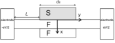
To evaluate the magnitude of this effect we have analyzed a simple model problem below. Namely, we investigate correlations in F1-SF1F2-F1 structures (see Fig. 1) that represent a long thin ferromagnetic wire F1 with the length It connects two massive normal electrodes. In its middle part the F1 layer is in contact with thick superconducting film S located on the top of the wire and thin ferromagnetic film F2 placed on the bottom of the wire (the lengths, of S and F2 films are identical). Magnetization vector of the long ferromagnetic wire is constant and it is directed along F1F2 interface. Magnetization vector of the short ferromagnetic film F2 is declined from the first vector on an angle thus providing conditions for realization of long-range triplet superconducting correlations in the structure. Here we present results of calculations for DoS and differential conductance along F1 film in F1-SF1F2-F1 structure with noncollinear magnetizations of ferromagnetic layers that also differs with values of exchange energies. The calculations are done in the diffusive limit in the framework of the Usadel equations for both linear and nonlinear cases. We present differential conductance of the F1 film as a function of angle . We show that maximum value of differential conductance is achieved not at (as it was found in BVE1 and Vasenko for out of plane geometry for normal current injection), but at some intermediate angle that depends on difference between the values of exchange energy of F films. We also investigate influence of suppression parameter on F1F2 interface on the shape of differential conductance.
We will discuss properties of the structure in the frame of Usadel equations that can be written as:
| (1) |
where parameter for F2 layer and for F1 film, ( are Pauli matrices), and are normalized on exchange energies of upper and lower F films, respectively, is the diffusion coefficient, is a quasiparticle energy. Green’s function is matrix
Here are retarded, advanced and Keldysh Green’s functions, correspondingly. The elements of matrix can be connected by distribution function (which is matrix):
| (2) |
In thermodynamic equilibrium, that in our case is achieved in the electrodes (see Fig.1), the distribution function is expressed by
| (3) |
where is an applied voltage (Fig. 1). Consequently, it is sufficient to determine only retarded function. This function can be represented as
where are condensate Green’s functions describing singlet, short-range and long-range triplet correlations; are normal Green functions, respectively. With these definitions normalization condition transforms to
| (4) |
Equation (1) must be supplemented by boundary conditions matching Green’s functions across the interfaces
| (5) |
| (6) |
At
| (7) |
while electron energy distribution functions are equal to their equilibrium values (3). Here the indices, and, refer to the upper or lower layer with respect to the SF1 and F1F2 boundaries.
Transport properties of both F1F2 and F1S interfaces are characterized by the interface parameters
| (8) |
Here and are the resistances and area of the F1F2 and F1S interfaces, and, are the decay lengths and diffusion coefficients of S and F materials, while and are their resistivities.
To simplify the problem we assume below that normal state resistivities and coherence lengths of ferromagnetic films are identical ( at F1F2 interface), ferromagnetic films are thin. The second assumption allows us to transfer solution of the problem (1)-(6) to a one-dimensional one (see Karminskaya1 -Karminskaya2 for the details). We also assume that suppression parameters at F1S interface satisfy the condition allowing to ignore the suppression of superconductivity in S electrode. We assume further, that the length, is smaller compare to the characteristic lengths of inelastic scattering inside the F1 layer.
Under the above assumptions it is possible to derive from (1) the equation for electron energy distribution for F1-SF1F2-F1 structure in the form of diffusion equation
Integrating this equation with boundary conditions (7) we get expression for distribution function and from the general expression for current
| (9) |
and (2) we arrive at
| (10) |
where
In the limit of zero temperature from (10) for normalized differential conductance of long ferromagnetic film in the direction along F1F2 interface we have
| (11) |
Expression (11) can be simplified in the linearized case when suppression parameter is large enough. In this limit superconductivity induced into F1 wire is small and in the zero approximation Taking into account normalization condition (4), we can express through the other functions in the next approximation and transforms expression (11) to:
| (12) |
Note, that expression for differential conductance similar to Eq. (12) was obtained for SNN’ structure in Volkov . Conductance in superconducting hybrids in a similar T-shaped geometry was further studied in Nazarov ; Golubov-1 (see review in Belzig ) and in Asano2007 . However, in the structures considered in Nazarov ; Golubov-1 ; Belzig no ferromagnetic layers were attached and therefore there were no odd superconducting correlations. In the structure considered in Asano2007 there also were no ferromagnetic layers, but odd triplet correlations were generated due to proximity effect between a p-wave superconductor and a diffusive N-layer.
We start our analysis of processes in F1-SF1F2-F1 structure by considering the case of a transparent F1F2 interface () This limiting case is simple. However, it reveals the main effects without any distortion due to the influence of the F1F2 interface. In the linearized case analytical solutions of the problem ((1)-(7)) for condensate functions in free part of upper F film can be easily derived:
| (13) |
| (14) |
| (15) |
In these expressions , , , is the modulus of the order parameter of superconductor, . It is necessary to note that to get (13)-(15) we also neglect suppression of Green’s functions in the part of F1 film located under superconductor due to proximity effect and use the rigid boundary conditions at
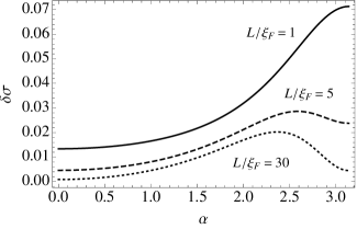
Fig. 2 shows a dependence of correction to differential conductance () normalized to conductance in the normal state as a function of misorientation angle calculated at zero voltage from (12)-(15) for three different lengths of the long ferromagnetic film (). Here we consider that exchange energies of the two F films are different (). Note that at the conditions of the linear approximation are violated at zero voltage.
For short upper ferromagnetic film () conductance rises from to monotonically since all correlations are still present in the structure and magnetic configuration for corresponds to smaller average exchange energy in comparison with . It is also seen from the figure that the shape of dependencies begins to change with increase of . The reason of this transformation is that singlet and short-range triplet components begin to decrease very fast deep into long parts of upper F film in comparison with long-range triplet part that decreases slowly. For (dotted line in Fig. 2) as well as in a limit of long upper ferromagnetic film, only these long-range triplet correlations can be taken into account. Expressions (12)-(14) give in this case
| (16) |
It is seen that in a vicinity of the angles and correction to the conductivity is negligible. This is a consequence of the fact that at these angles there are no long-range triplet correlations in the structure.
The dependence of differential conductance has a maximum at some intermediate angle
It is seen that the position of the maximum is the function of exchange energies only and it is always located at since exchange energies are different in this case. In the area near long-range triplet correlations declare themselves very strongly.
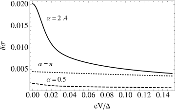
This can also be seen from Fig.3. It shows dependencies of correction to differential conductance on applied voltage for long upper ferromagnetic film for three different misorientation angles , and . At zero voltage there is a strong peak in differential conductance at . It is exactly the angle at which there is the maximum in dependence calculated for (see dotted line in Fig. 2). With inclination of angle from the height of the peak decreases since influence of long-range triplet component decreases.
Let us discuss behavior of differential conductance beyond the linearized case for arbitrary value of parameter . To calculate it, the nonlinear equations (1)-(6) were solved numerically using shooting method.
Fig. 4 shows dependence of conductance of a long upper ferromagnetic film on angle at zero voltage. This conductance is caused by long-range triplet correlations since for long ferromagnetic film only these correlations are strong enough. At behavior of conductance is still similar to the one seen from Fig.2. As SF interface becomes more transparent (suppression parameter decreases) peaks on the graph get higher. Further reduction of the suppression parameter results in appearance of an angle interval in which correction to differential conductance is zero, peaks on the boarders of the interval increase sharply(see dashed line Fig. 4).
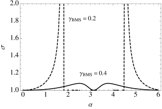
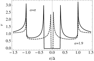
Appearance of strong peaks can be understood from Fig. 5. It shows dependence of DoS, , on energy, calculated numerically for , , , and two values of misorientation angle between magnetization vectors (solid line) and (dashed line). At there are two peaks in density of states located at and at the position of minigap. Deviation of the angle from leads to increase of effective exchange energy. As the result, the position of minigap shifts to smaller energy and there exists an angle at which the minigap becomes zero and position of the peak in the density of states is localized at zero energy. It occurs at that is exactly at the angle at which there are peaks in dependence presented in Fig. 4.
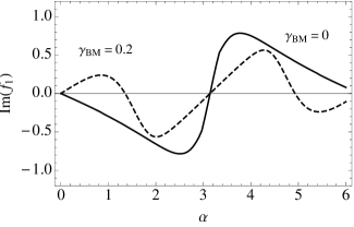
As it was discussed earlier in Karminskaya2 for SF1F2 structure, suppression parameter at F1F2 interface can strongly influence on behavior of long-range triplet correlations leading to additional phase-slip at F1F2 interface. Indeed, taking into account nonzero value of parameter at F1F2 interface we obtain that behavior of component in F1-SF1F2-F1 structure changes significantly (Fig. 6). Dashed line () shows that triplet component changes it’s sign at some intermediate angle, which is not equal to or . The magnitude of this angle depends on difference between and , and on suppression parameters and . With increase of suppression parameters and decrease of it moves towards .
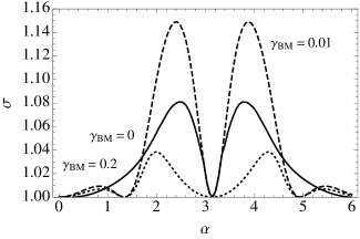
Long-range triplet correlations prevail in the long F1 film of F1-SF1F2-F1 structure, so the features that are seen on Fig. 6 will remain in conductance. Fig. 7 shows dependence of differential conductance of upper F1 film on angle at zero voltage for several values of suppression parameter . With increase of the shape of conductance changes due to changing of the long-range triplet component (dashed line and dotted lines). In the case of finite transparency of F1F2 interface one maximum in differential conductance transforms into two maximums. Also at maximum value of conductance (dashed line) can be even larger than for structure with ideal transparency of F1F2 interface (solid line). This fact is in good agreement with the discussion performed in Karminskaya2 .
In conclusion, we have investigated conductance of a long ferromagnetic film in F1-SF1F2-F1 structure. In the collinear magnetization case, the conductance rapidly decreases with increase of length of the F1 film. However, in the configuration with noncollinear magnetizations the conductance decrease slowly due to the generation of long-range triplet superconducting correlations. Strong dependence of the differential conductance on misorientation angle allows to control the conductance by changing directions of magnetization of one ferromagnetic film. Further, we demonstrate that long-range triplet correlations manifest themselves as a zero-bias peak in the case of perfect transparency of F1F2 interface, while a two-peak structure is realized in the case of finite transparency. These features may serve as a diagnostic tool for characterization of interfaces in superconducting hybrid structures.
The work is supported in part by Russian and Belarusian Funds for Basic Research under RFBR-BFBR Grants No. l2-02-90010 (M.Yu.K.)and No. Fl2R-014 (S.L.P.), EU-Japan collaboration program "IRON SEA" and by the Ministry of Education and Science of the Russian Federation.
References
- (1) Bulaevskii L N, Kuzii V V and Sobyanin A A 1977 Pis’ma Zh. Eksp. Teor. Fiz. 25 314
- (2) Buzdin A I, Bulaevskii L N and Panyukov S V 1982 Pis’ma Zh. Eksp. Teor. Fiz. 35 147
- (3) Buzdin A I and Kupriyanov M Yu 1991 Pis’ma Zh. Eksp. Teor. Fiz. 53 308
- (4) Bergeret F S, Volkov A F and Efetov K B 2001 Phys. Rev. Lett. 86 4096
- (5) Kadigrobov A, Shekhter R I and Jonson M 2001 Europhys. Lett. 54 394
- (6) Volkov A F, Bergeret F S and Efetov K B 2003 Phys. Rev. Lett. 90 117006
- (7) Bergeret F S, Volkov A F and Efetov K B 2003 Phys. Rev. B 68 064513
- (8) Volkov A F, Fominov Ya V and K. B. Efetov 2005 Phys. Rev. B 72 184504
- (9) Bergeret F S, Volkov A F and Efetov K B 2005 Rev. Mod. Phys. 77 1321
- (10) Buzdin A I 2005 Rev. Mod. Phys. 77, 935
- (11) Golubov A A, Kupriyanov M Yu, and Il’ichev E 2004 Rev. Mod. Phys. 76, 411
- (12) Volkov A F and Efetov K B 2010 Phys. Rev. B 81 144522
- (13) Trifunovic L and Radovic Z 2010 Phys. Rev. B 82 020505(R)
- (14) Houzet M and Buzdin A I 2007 Phys. Rev. B 76 060504
- (15) Eschrig M, Kopu J, Cuevas J C and Schoen G 2003 Phys. Rev. Lett. 90 137003
- (16) Loefwander T, Champel T, Durst J and Eschrig M 2005 Phys. Rev. Lett. 95 187003
- (17) Eschrig M and Loefwander T 2008 Nat. Phys. 4 138
- (18) Eschrig M 2011 Phys. Today 64 43
- (19) Braude V and Nazarov Yu V 2007 Phys. Rev. Lett. 98 077003
- (20) Asano Y, Tanaka Y and Golubov A A 2007 Phys. Rev. Lett. 98 107002
- (21) Asano Y, Sawa Y, Tanaka Y and Golubov A A 2007 Phys. Rev. B 76 224525
- (22) Karminskaya T Yu and Kupriyanov M Yu 2007 Pis’ma Zh. Eksp. Teor. Fiz. 86 65 Karminskaya T Yu and Kupriyanov M Yu 2007 JETP Lett. 86 61 (Engl. transl.)
- (23) Karminskaya T Yu, Kupriyanov M Yu and Golubov A A 2008 Pis’ma Zh. Eksp. Teor. Fiz. 87 657 Karminskaya T Yu, Kupriyanov M Yu and Golubov A A 2008 JETP Lett. 87570 (Engl. transl.)
- (24) Karminskaya T Yu, Golubov A A and Kupriyanov M Yu 2011 Phys. Rev. B 84 064531
- (25) Beri B, Kupferschmidt J N, Beenakker C W J and Brouwer P W 2009 Phys. Rev. B 79 024517
- (26) Kupferschmidt J N and Brouwer P W 2011 Phys. Rev. B. 83 014512
- (27) Fominov Ya V, Golubov A A and Kupriyanov M Yu 2003 Pis’ma Zh. Eksp. Teor. Fiz. 77 609 Fominov Ya V, Golubov A A and Kupriyanov M Yu 2003 JETP Lett. 77510 (Engl. transl.)
- (28) Fominov Ya V, Golubov A A, Karminskaya T Yu, Kupriyanov M Yu, Deminov R G and Tagirov L R 2010 Pis’ma Zh. Eksp. Teor. Fiz. 91 329 Fominov Ya V, Golubov A A, Karminskaya T Yu, Kupriyanov M Yu, Deminov R G and Tagirov L R 2010 JETP Lett. 91 308 (Engl. transl.)
- (29) Vasenko A S, Ozaeta A, Kawabata S, Hekking F W J, Bergeret F S 2013 Journal of Superconductivity and Novel Magnetism 26 1951
- (30) Meng H, Wu X, Zheng Z and Xing D Y 2013 Long-Range triplet Josephson Current Modulated by the Interface Magnetization Texture, cond-mat. supr-con. arXiv:1309.6807.
- (31) Kawabata S, Asano Y, Tanaka Y, and Golubov A A 2013 Journal of the Physical Society of Japan 82 124702
- (32) Ryazanov V V, Oboznov V A, Rusanov A Yu, Veretennikov A V, Golubov A A, and Aarts J 2001 Phys. Rev. Lett. 86, 2427
- (33) Oboznov V A, Bol’ginov V V, Feofanov A K, Ryazanov V V, and Buzdin A I 2006 Phys. Rev. Lett. 96 197003
- (34) Kontos T, Aprili M, Lesueur J, et al. 2002 Phys. Rev. Lett. 89, 137007
- (35) Sellier H, Baraduc C, Lefloch F, and Calemczuck R 2003 Phys. Rev. B 68, 054531
- (36) Blum Y, Tsukernik A, Karpovski M, et al. 2004 Phys. Rev. B 70, 214501 (2004).
- (37) Bell C, Loloee R, Burnell G, and Blamire M G 2005 Phys. Rev. B 71, 180501 (R)
- (38) Weides M, Kemmler M, Kohlstedt H, Buzdin A I, Goldobin E, Koelle D, Kleiner R 2006 Appl. Phys. Lett. 89, 122511
- (39) Pfeiffer J, Kemmler M, Koelle D, Kleiner R, Goldobin E, Weides M, Feofanov A K, Lisenfeld J, Ustinov A V 2008 Phys. Rev. B 77 214506 (2008).
- (40) Sosnin I, Cho H, Petrashov V T and Volkov A F 2006 Phys. Rev. Lett. 96 157002
- (41) Keizer R S, Goennenwein S T B, Klapwijk T M, Miao G, Xiao G and Gupta A 2006 Nature London 439 825
- (42) Robinson J W A, Witt J D S and Blamire M G 2010 Science 329 59
- (43) Sprungmann D, Westerholt K, Zabel H, Weides M and Kohlstedt H 2010 Phys. Rev. B 82 060505(R)
- (44) Wang J, Singh M, Tian M, Kumar N, Liu B, Shi C, Jain J K, Samarth N, Mallouk T E and Chan M H W 2010 Nat. Phys. 6 389
- (45) Anwar M S, Czeschka F, Hesselberth M, Porcu M and Aarts J 2010 Phys. Rev. B 82 100501(R)
- (46) Anwar M S and Aarts J 2011 Supercond. Sci. Technol. 24024016
- (47) Anwar M S, Veldhorst M, Brinkman A and Aarts J. 2012 Appl. Phys. Lett. 100 052602
- (48) Khaire T S, Khasawneh M A, Pratt Jr W P and Birge N O 2010 Phys. Rev. Lett. 104 137002
- (49) Khasawneh M A, Khaire T S, Klose C, Pratt Jr W P and Birge N O 2011 Supercond. Sci. Technol. 24 024005
- (50) Klose C, Khaire T S, Wang Y, Pratt Jr W P Birge N O, McMorran B J, Ginley T P, Borchers J A, Kirby B J, Maranville B B and Unguris J 2012 Phys. Rev. Lett. 108 127002
- (51) Leksin P V, Garif’yanov N N, Garifullin I A, Schumann J, Kataev V, Schmidt O G and Buehner B 2011 Phys. Rev. Lett. 106 067005
- (52) Zdravkov V I, Kehrle J, Obermeier G, Lenk D, Krug von Nidda H -A, Mueller C, Kupriyanov M Yu, Sidorenko A S, Horn S, Tidecks R and Tagirov L R 2013 Phys. Rev. B 87 144507
- (53) Herr A, Naaman O, Miller D, Herr Q, "Josephson Magnetic Random Access Memory (JMRAM)", In Conference Program Book of 2012 Applied Superconductivity Conference, October 7 - 12, 2012, Portland, Oregon, p. 608.
- (54) Newman N, Herr A, Rowell J M, Rizzo N, Qader M, Singh R K, Ofer Naaman O, Miller D, Materials and processing requirements for Josephson MRAM (JMRAM) devices for superconductor memory applications, In Conference Program Book of 2012 Applied Superconductivity Conference, October 7 - 12, 2012, Portland, Oregon, p. 965.
- (55) Holmes D S, Ripple A L, and Manheimer M A, 2013 IEEE Trans. on Appl. Supercond. 23 1701610 https://www.fbo.gov/index?s=opportunity&mode= form&id=d3f719e5d3cde3c409486f6228122908&tab= documents&tabmode=list
- (56) Ryazanov V V, Bol’ginov V V, Sobanin D S, Vernik I V, Tolpygo S K, Kadin A M, Mukhanov O A 2012 Physics Procedia 36 35
- (57) Larkin T I, Bol’ginov V V, Stolyarov V S, Ryazanov V V, Vernik I V, Tolpygo S K and O. A. Mukhanov 2012 Appl. Phys. Lett. 100 222601
- (58) Vernik I V, Bol’ginov V V, Bakurskiy S V, Golubov A A, Kupriyanov M Yu, Ryazanov V V and Mukhanov O A 2013 IEEE Tran. Appl. Supercond. 23 1701208
- (59) Bakurskiy S V, Klenov N V, Soloviev I I, Bol’ginov V V, Ryazanov V V, Vernik I I, Mukhanov O A, Kupriyanov M Yu and Golubov A A 2013 Appl. Phys. Lett 102 192603
- (60) Bakurskiy S V, Klenov N V, Soloviev I I, Kupriyanov M Yu and Golubov A A 2013 Phys. Rev. B 88 144519
- (61) Volkov A F, Zaitsev A V, Klapwijk T M 1993 Physica C 210 21
- (62) Nazarov Yu V and Stoof T H, 1996 Phys. Rev. Lett. 76, 823 Phys. Rev. B 53, 14496.
- (63) Golubov A A, Wilhelm F K, Zaikin A D 1997 Phys. Rev. B 55 1123
- (64) Belzig W, Wilhelm F K, Bruder C, Schoen G, and Zaikin A D, 1999 Superlattices Microstructructures 25, 1251
- (65) Asano Y, Tanaka Y, Golubov A A, and Kashiwaya S 2007 Phys. Rev. Lett. 99 067005