Radially Polarized, Half-Cycle, Attosecond Pulses from Laser Wakefields through Coherent Synchrotron Radiation
Abstract
Attosecond bursts of coherent synchrotron-like radiation are found when driving ultrathin relativistic electron disks in a quasi-one-dimensional regime of wakefield acceleration, in which the laser waist is larger than the wake wavelength. The disks of overcritical density shrink radially due to the focusing wake fields, thus providing the transverse currents for the emission of an intense, radially polarized, half-cycle pulse of about 100 attoseconds in duration. The electromagnetic pulse first focuses to a peak intensity 10 times larger () than the driving pulse and then emerges as a conical beam. Saturation of the emission amplitudes is derived analytically and in agreement with particle-in-cell simulation. By making use of gas targets instead of solids to form the ultrathin disks, the new scheme allows for high repetition rate required for applications.
pacs:
52.38.Kd, 52.59.-f, 52.59.Ye, 42.65.KyGreat efforts have been devoted to obtain extreme-ultraviolet (XUV) and soft X-ray pulses having attosecond duration. They open the door to attosecond spectroscopy of bound electrons Krausz2009 . An established method to produce such pulses relies on atomic harmonics excited by ultrafast lasers at an intensity below gasHHG . Harmonics from solid surfaces Teubner2009 make use of relativistic optics () Mourou and allow for much brighter sources. Single attosecond spikes can be isolated from trains of pulses by means of high-pass filters HHG . By temporally rotating either the surface geometry Naumova2004 or the driver wavefront Wheeler2012 , individual attosecond pulses can be obtained even without filtering.
In this Letter, we follow a different path, producing intense isolated attosecond pulses from underdense plasmas rather than solids. With gas targets the condition of ultrahigh laser contrast is greatly relaxed, and a bright source allowing for high repetition rate may become possible. The new path is based on wakefield acceleration driven by an intense short laser pulse. As it is well known, these relativistic plasma waves exhibit strong accelerating and focusing fields for electrons. They promise acceleration to high energies over a short distance LWFA . Often the laser beam is tightly focused to reach highest possible intensity with waist , where is the plasma wavelength and the normalized laser amplitude at wavelength . Plasma electrons are then pushed sideways by the light pressure, creating bubble-like wakes. Some electrons circling around the bubble are transversely injected at the rear vertex and then accelerated forming a narrow bunch Kostyukov2009PRL . This is known as the bubble regime of wakefield acceleration Bubble . An important feature is that the accelerating bunch oscillates in the wake forced by the focusing fields and emits bright betatron radiations Betatron .
Here we make use of a different regime of wakefield acceleration, occurring for laser waists larger than wake wavelength. Wake electrons now perform mainly one-dimensional (1D) longitudinal motion due to weak radial expelling. The density wave crests show disk-like profiles as visualized in experiments Matlis2006 . Most notably, they compress into dense sheets when driven close to wavebreaking. Actually such ultrathin wave crests have been used as relativistic mirrors to backscatter femtosecond probe pulses FlyingMirror . In this way, attosecond XUV/X-ray pulses are obtained owing to simultaneous frequency upshift and pulse shortening by Dopper factors of , where with the wake’s phase velocity and the light speed in vacuum. In this work, however, we follow another line that does not require a second pulse, but leads to self-emission of a bright attosecond pulse from the dense electron sheet itself. For this to happen, the electron sheet has to be injected and accelerated in the wakefield. Different from the ultrathin density crest belonging to the quasi-1D waveform FlyingMirror , the injected sheet contracts in transverse direction due to the focusing wake fields, while boosted at the same time in energy by wakefield acceleration. The central new result of this Letter is that a strong unipolar attosecond pulse is produced by the transverse currents formed during the contraction motion. This coherent attosecond source is also in contrast to the incoherent femtosecond betatron X-rays normally obtained so far Betatron .
Different ways may be used to induce injection of such electron sheets Nanosheet . A simple method has been described using an up-ramp density profile followed by a plateau Li2013prl . Wavebreaking then occurs at the transition point and leads to a sudden longitudinal injection into the quasi-1D wake, different from the continuous transverse injection in the bubble regime Kostyukov2009PRL ; Bubble . The key point is that, along the ramp, the wave crest travels at superluminal speed, preventing premature injection. At the transition to the plateau, the density spike is injected as a whole due to fast switching of . It forms an ultrathin (few nm) overcritical dense electron disk that accelerates in the wakefield.
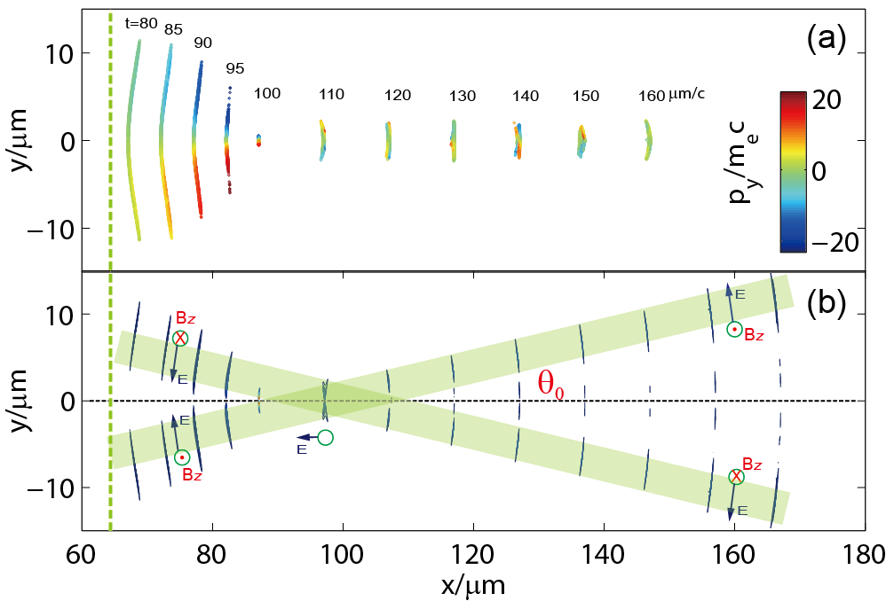
The evolution of an electron sheet in the wakefield and the associated radiation flash are first illustrated in Figs. 1(a) and 1(b). It is seen that the sheet contracts transversely to a smallest diameter in tens of laser periods after injection, while accelerating longitudinally up to a highly relativistic -value (compare Fig. 3). It is in this short time interval that the attosecond pulse is emitted. As found in Fig. 1(b), the pulse is first attached to the electron sheet, but then propagates along a cone, while the electrons move closer to the axis in a channel of almost constant diameter.
These results are obtained from two-dimensional particle-in-cell (2D PIC) simulations Fonseca2002 . Here in order to control trapping of the electron sheet, the self-injection method with particular density tailoring was employed Li2013prl . A linearly polarized (along direction), (full width at half maximum) laser pulse of peak intensity irradiates an underdense plasma slab with a -long ramping front edge. The plateau density is with the critical density for . A laser waist of is enough for the formation of wide sheets in the quasi-1D regime. In the simulation, grids cells per were used and sufficient to resolve the attosecond spikes; even higher resolutions gave almost the same results. Furthermore, an initial electron temperature of was chosen to mimic field ionization by prepulse.
We now discuss the radiation process in general. The injected electrons are diverted by the focusing wake fields toward the central axis according to . Here is the normalized transverse velocity; and the focusing field have, respectively, been normalized by and with electron mass , elementary charge and laser frequency . Near the central axis, the focusing field, , is almost linear in radius and the ambient density . Trapped electrons then perform synchrotron-like motion with curvature radius and emit broadband radiation with cutoff frequency Shiozawa . However, there are a couple of new features when compared with bubble betatron radiation Betatron . First, the high density of the sheet, typically larger than Li2013prl , enables synchrotron emission in a coherent manner. Coherence occurs provided that a sufficiently large number of electrons resides in a volume with scale length equal to the radiation wavelength in the rest frame of electrons. For the present case, it requires the sheet density to satisfy , where radiation at the cutoff wavelength is assumed. Considering , this criteria is readily met even for . Second, due to axial symmetry and inward acceleration of the disk electrons, a radially polarized half-cycle electromagnetic pulse is emitted. Third, with the increase of by wakefield acceleration, the radiated power grows Shiozawa . That means the dominant emission profile roughly overlaps the sheet during amplification, having an attosecond duration. It is worth noting that similar radially polarized pulses have actually been detected from thin photoconductors, where annular microelectrodes induced the radial current Kan2013 . Due to the static wafer plane, however, only pulses of picosecond duration were observed, determined by the lifetime of the radiating current.
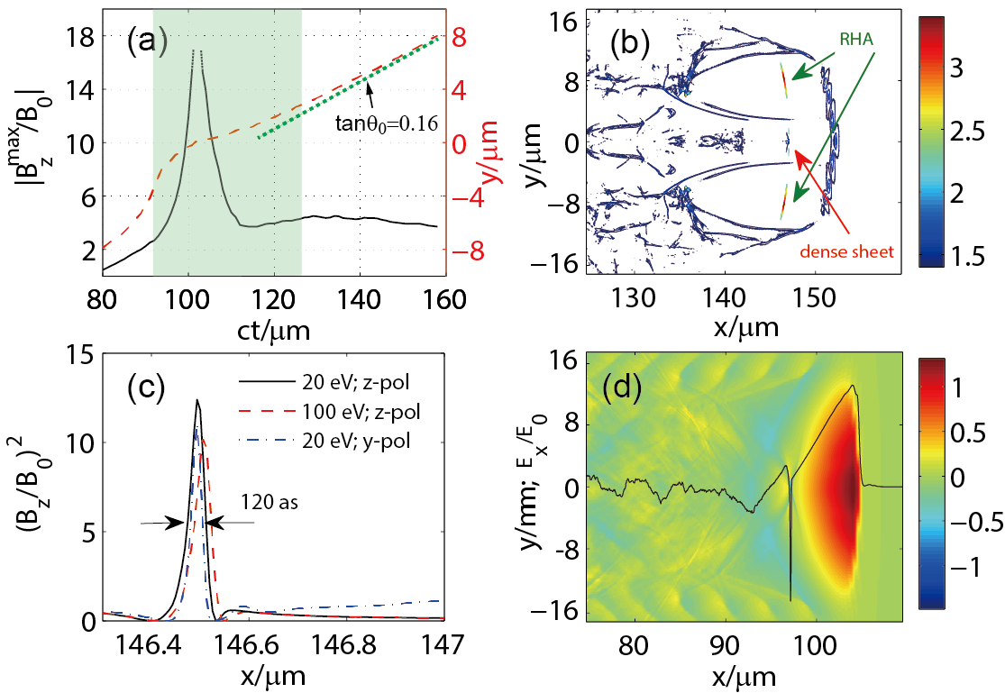
These features are well illustrated in the sample simulation. Figure 2(a) records how the peak field of the radially polarized, half-cycle, attosecond (RHA) pulse evolves; is the normalizing field. According to Fig. 1(b), the pulse emerges in three stages: pulse generation during initial sheet contraction, beam crossing on axis, and finally annular beam propagating along a cone. At the phase of crossing, the emission focuses to a maximum of , as found in the shaded region of Fig. 2(a). This corresponds to a peak intensity greater than . After complete separation (), the actual peak field shows up as , corresponding to . Importantly, Fig. 2(b) shows how the RHA pulse propagates at later time. The initial quasi-1D wake is evolving into a complex broken-wave pattern due to laser evolution Xujc2007 . The half-cycle pulse as short as (see Fig. 2(c)) is propagating inside the wake but deviated from the axis. It contains a broadband XUV spectrum extending up to in photon energy. In the present case, the annular beam carries a total energy of , which is of the incident laser energy. The radial polarization of the attosecond pulse is confirmed in Fig. 2(c), where switching polarization of the driving pulse from to direction has almost no effect on the emission profile. We have checked that the annular beam is uniform azimuthally when obtained in 3D simulation.
The basic dynamics of RHA generation can be derived from a simplified model. It assumes that a flat, monoenergetic electron sheet of delta-like density profile with finite areal density and no initial transverse momentum is injected into a wakefield of uniform accelerating and focusing fields. Coherent radiation from the electron sheet is described by the 1D wave equation , where is the radiating current with the velocity integrated over a short transverse acceleration Wuhc2012 . The radiated field is first calculated in the rest frame of the sheet with Lorentz factor and then transformed to the laboratory frame; the result is given by
| (1) |
where denotes the velocity in the rest frame. Equation (1) indicates that the radiated power grows , while follows from . Taking into account the radiated field , the total fields can be expressed as and , where and are the longitudinal and transverse wake fields, respectively. Inserting the expression of Eq. (1), the energy equation reads
| (2) |
Assuming initially, wakefield acceleration first boosts the -value rapidly, which then saturates due to radiation damping at a rate . Saturation occurs for , leading to the saturated field
| (3) |
where is evaluated at the saturation instant.
It is clear that wakefield acceleration has played an essential role in the attosecond pulse generation. This marks a most prominent feature of the present scheme. Equation (3) suggests that can be large provided that is small initially and the saturated level can be maintained for a long period. There are a couple of other effects not yet included. For the sample case, the injected sheet is not perfectly flat but slightly curved as seen in Fig. 1(a). Due to the sudden longitudinal injection, a curved wake wavefront FlyingMirror ; Matlis2006 directly maps into the injected sheet profile and the sheet electrons also inherit finite transverse velocities. These will cause their transverse contraction even without the focusing fields, and the radiation process is ultimately limited by deformation of the sheet profile.
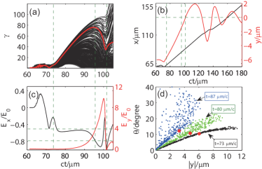
Let us explore these effects by particle tracking. Figure 3 presents the results for a group of electrons uniformly distributed in the lower half of the electron sheet. According to Figs. 3(b) and 3(c), the sheet is injected at and focuses to the central axis at . During contraction these electrons develop a broad spread due to high thermal temperature; see Fig. 3(a). However, the overcritical density and ultrathin feature of the sheet ensure the coherence of the attosecond pulse. It is hardly affected by initial plasma temperatures; results given for and in Fig. 2(c) show little difference. Moreover, as found in Fig. 3(d), the transverse velocities of the sheet, inherited from wave crest, scale almost linearly with (details see supplemental material) and increase with time due to transverse acceleration. This suggests that the sheet can be subdivided into a sequence of ring-shaped segments defined by their particular . Applying the simplified model to each segment with coordinate frame rotated by angle from the normal - axis, the resulting pointing direction of the radiated electric field will deviate from the axis; see the schematic drawing in Fig. 1(b). A clear evidence for this is shown in Fig. 2(d), where a sharp negative field shows up at the on-axis overlap joint during beam crossing. Emissions from segments of different then converge due to propagation. This accounts for the focusing effect observed in Fig. 2(a). The finally observed RHA pulse (Fig. 2(b)) builds up from all segment contributions weighted according to Eq. (1). As it turns out, largest contributions stem from ring segments with medium radius. For the present case, the conical angle of the radiation peak is measured to be in Fig. 2(a). To evaluate this peak field, a typical electron is highlighted in Fig. 3; it is initially located near the center of the lower half and belongs to the most energetic ones after acceleration. According to Eq. (3), the peak field amounts to , which is in fair agreement with the observation of after . Here is the longitudinal electric field felt by the electron at the saturation instant and is extracted from Figs. 3(a) and 3(c).
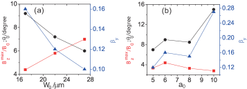
The present RHA generation is robust against changing laser and plasma parameters, provided that they are sufficient to induce the sheet injection. Larger focal spots of the driving pulse generally lead to smaller initial transverse velocities of the injected sheet, generating higher radiation peaks following Eq. (3). This is shown in Fig. 4(a) where and scale almost linearly with . While scanning the laser amplitude for fixed plasma density , an optimal value of exists as seen in Fig. 4(b).
Petawatt lasers, presently coming up, will provide sufficiently high power for the high intensities and the relatively broad focal spots required here. The sample case shown above used a single driving pulse delivering in . These parameters are well within the ELI-facility capabilities ELI and are also becoming available commercially. The conical angle of the RHA beam is typically less than , thereby allowing refocusing even at half-meter distance by a concentric mirroring tube with diameter less than ; such techniques have actually been implemented in the measurement of wakefield-based electro-optic shocks Helle2010PRL . The RHA pulse should also be easily distinguished from other sources due to its radial polarization Schnell2013 and hollow pattern.
In conclusion, we have identified novel attosecond bursts of coherent synchrotron radiation from laser wakefield acceleration. The attosecond feature does not derive from an ultrathin solid foil Wuhc2012 or surface layer Nanobunch , but arises from intrinsic features of nonlinear plasma waves, namely steepening and breaking. It makes use of quasi-1D wavebreaking, allowing to trap ultrathin electron sheets in the wakefield. The electron sheet contracts, while boosted in energy, and is found to emit a relativistically intense attosecond pulse. Pulse energy exceeding can be obtained with the laser-to-RHA conversion efficiencies beyond . Besides being a bright source for attosecond applications, this burst will also provide excellent diagnostics for the wavebreaking dynamics Thomas2007prl in the quasi-1D regime and corresponding electron sheet generation Li2013prl .
ZMS would like to thank the OSIRIS Consortium at UCLA and IST (Lisbon, Portugal) for providing access to OSIRIS 2.0 framework. This work is supported in part by the National Basic Research Program of China (Grant No. 2013CBA01504), the National Science Foundation of China (Grant No. 11121504, 11205101, 11374209 and 11374210), the MOST international collaboration project (Grant No. 2014DFG02330), and the EPSRC, UK. Simulations were performed on Magic Cube at Shanghai Supercomputer Center and at Shanghai Jiao Tong University.
References
- (1) F. Krausz and M. Ivanov, Rev. Mod. Phys. 81, 163 (2009).
- (2) P. B. Corkum and F. Krausz, Nat. Phys. 3, 381 (2007); K. Midorikawa, Jap. J. Appl. Phys. 50, 090001 (2011).
- (3) U. Teubner and P. Gibbon, Rev. Mod. Phys. 81, 445 (2009).
- (4) G. A. Mourou, T. Tajima, and S. V. Bulanov, Rev. Mod. Phys. 78, 309 (2006); G. Mourou and T. Tajima, Science 331, 41 (2011).
- (5) A. Pukhov, T. Baeva, D. an der Brgge, and S. Mnster, Eur. Phys. J. D 55, 407 (2009); G. D. Tsakiris, K. Eidmann, J. Meyer-ter-Vehn, and F. Krausz, New J. Phys. 8, 19 (2006).
- (6) N. M. Naumova et al., Phys. Rev. Lett. 92, 063902 (2004).
- (7) J. A. Wheeler et al., Nat. Photon. 6, 829 (2012).
- (8) T. Tajima and J. M Dawson, Phys. Rev. Lett. 43, 267 (1979); E. Esarey, C. Schroeder, and W. Leemans, Rev. Mod. Phys. 81, 1229 (2009).
- (9) I. Kostyukov, E. Nerush, A. Pukhov, and V. Seredov, Phys. Rev. Lett. 103, 175003 (2009).
- (10) A. Pukhov and J. Meyer-ter-Vehn, Appl. Phys. B 74, 355 (2002); W. Lu et al., Phys. Rev. Lett. 96, 165002 (2006).
- (11) A. Rousse et al., Phys. Rev. Lett. 93, 135005 (2004); S. Corde et al., Rev. Mod. Phys. 85, 1 (2013).
- (12) N. H. Matlis et al., Nat. Phys. 2, 749 (2006).
- (13) S. V. Bulanov, T. Esirkepov and T. Tajima, Phys. Rev. Lett. 91, 085001 (2003); A. S. Pirozhkov, et al., Phys. Plasmas 14, 123106 (2007).
- (14) An electron sheet may, in principle, be externally injected into a broad wakefield driven by petawatt lasers. Possible sheet production methods were proposed, for example, in V. V. Kulagin, V. A. Cherepenin, M. S. Hur, and H. Suk, Phys. Rev. Lett. 99, 124801 (2007); H. C. Wu, J. Meyer-ter-Vehn, J. Fernndez, and B. M. Hegelich, Phys. Rev. Lett. 104, 234801 (2010).
- (15) F. Y. Li et al., Phy. Rev. Lett. 110, 135002 (2013).
- (16) R. Fonseca et al., Lecture Notes in Computer Science. 2331, 342-351 (Springer Berlin, Heidelberg, 2002).
- (17) T. Shiozawa, Classical Relativistic Electrodynamics, Springer-Verlag (Berlin, Heidelberg, 2004), pp77-82.
- (18) K. Kan et al., App. Phys. Lett. 102, 221118 (2013).
- (19) J. Xu et al., New J. Phys. 12, 023037 (2010).
- (20) H. C. Wu and J. Meyer-ter-Vehn, Nat. Photon. 6, 304 (2012).
- (21) ELI-Extreme Light Infrastructure Science and Technology with Ultra-Intense Lasers WHITEBOOK, edited by G. A. Mourou, G. Korn, W. Sandner, and J. L. Collier (THOSS Media GmbH, Berlin, 2011).
- (22) M. H. Helle, D. Kaganovich, D. F. Gordon, and A. Ting, Phys. Rev. Lett. 105, 105001 (2010).
- (23) M. Schnell et al., Nat. Commun. 4, 2421 (2013).
- (24) B. Dromey, et al., Nat. Physics 8, 804 (2012); D. an der Brgge and A. Pukhov, Phys. Plasmas 17, 033110 (2010).
- (25) A. G. R. Thomas et al., Phys. Rev. Lett. 98, 054802 (2007).