A Novel Carrier Waveform Inter-Displacement Modulation Method in Underwater Communication Channel
Abstract
As the main way of underwater wireless communication, underwater acoustic communication is one of the focuses of ocean research. Compared with the free space wireless communication channel, the underwater acoustic channel suffers from more severe multipath effect, the less available bandwidth and the even complex noise. The underwater acoustic channel is one of the most complicated wireless communication channels. To achieve a reliable underwater acoustic communication, Phase Shift Keying (PSK) modulation and Passive Time Reversal Mirror (PTRM) equalization are considered to be a suitable scheme. However, due to the serious distortion of the received signal caused by the channel, this scheme suffers from a high Bit Error Rate (BER) under the condition of the low Signal to Noise Ratio (SNR). To solve this problem, we proposes a Carrier Waveform Inter-Displacement (CWID) modulation method based on the Linear Frequency Modulation (LFM) PSK and PTRM scheme. The new communication scheme reduces BER by increasing the difference from the carrier waveform for different symbols. Simulation results show the effectiveness and superiority of the proposed method.
Index Terms:
underwater acoustic communications, linear frequency modulation, PTRM, carrier waveform inter-displacement modulation.I Introduction
The ocean covers about 360 million square kilometers occupying of the earth’s surface. The ocean resources are important for human being. With the development of ocean commercial exploitation and ocean defense, a growing interest in underwater communication has been witnessed. Underwater cable communication suffers from high cost and inconvenience. Therefore, underwater wireless communication are considered as a better way of underwater communication. Radio waves have a severe attenuation when being transmitted in the water. Acoustic waves are the optimal carrier wave in underwater wireless communication [1]. As the main way of underwater wireless communication, underwater acoustic communication becomes more and more important in the field of ocean research [2].
Underwater acoustic channel is recognized as one of the most complex communication channels. Compared with the free space wireless communication channel, the underwater acoustic channel has a more severe multipath effect, a less available bandwidth, a more serious Doppler spreading and shifting, even a more complex noise[1, 3, 4]. The suitable modulation and equalization are necessary to implement a high speed and low BER underwater communication.
Multi-carrier modulation [5] and single-carrier modulation are the two main modulation methods today. A higher speed can be achieved by using multi-carrier modulation. However, the modulation method is sensitive with the frequency offset of the carrier-waves, which leads to a high BER in a poor environment [6]. Single-carrier modulation involves incoherent modulation and coherent modulation. Incoherent modulation was widely used in the early stage of underwater acoustic communication, for example Frequency Shift Keying (FSK) modulation. The advantages of incoherent modulation are simplicity and reliability. However, incoherent modulation are limited by a low bandwidth efficiency. With the increasing request of improving bandwidth efficiency, coherent modulation was used [1]. PSK modulation is the most widely used coherent modulation, which uses different initial phases to represent different symbols. Binary Phase Shift Keying (BPSK) modulation has a low BER due to the large difference of carrier-waves for different symbols. However, its bit transmission rate is low. M-ary Phase Shift Keying (MPSK) modulation can get a higher transmission bit rate, but with a higher BER. For example, for Quadrature Phase Shift Keying (QPSK) modulation, the speed is doubled compared with that of BPSK. However, the differences between carrier-waves of different symbols are reduced, it causes an increasing BER.
Due to the complexity of the underwater acoustic channel, the signals passing through it suffer from a more severe distortion compared to its counterpart in a free space wireless communication channel. Equalization is a one of the techniques to resist the distortion. Adaptive equalizations are the widely used equalizations in underwater acoustic communication [7, 8, 9, 10]. The underwater acoustic communication channel exhibits a long delay spread because of a large amount of multipath arrivals resulting from surface and bottom interactions. The long delay spread and rapid time variation of the channel causes the computation of adaptive decision feedback equalization too complex for real-time implementations [2]. Therefore, several advanced algorithms based on the structure of decision feedback equalizer were proposed, for example, a decision feedback equalizer coefficient placement algorithm for sparse reverberant channel [11], an adaptive decision feedback equalizer based on composed VFF-RLS and VSS-NLMS algorithm [12], a receiver using adaptive decision feedback equalizer and Bit Interleaved Coded Modulation with Iterative Decoding (BICM-ID) [13]. Compared with the original adaptive decision feedback equalization, these modified algorithms have lower computation consumption and better performance. However, they all suffer from error propagation due to the feedback of erroneous decisions in the loop. PTRM equalization can match the underwater acoustic channel automatically without any transcendental knowledge. PTRM equalization also reduces the computational computation.
The communication schemes using PSK modulation and PTRM equalization are recognized as a suitable underwater wireless communication scheme. An experiment was carried out in water tank using BPSK modulation [14], 7 chips Barker code, and PTRM equalization. The results showed that PTRM can decrease BER and increase communication distance. The BPSK and QPSK modulation together with PTRM were tested in [15], the results showed that the QPSK obtained a higher speed but a higher BER compared with BPSK. A SISO Irregular Repeat Accumulate (IRA) channel decoder was proposed to use together with Differential Binary Phase Shift Keying (DBPSK) modulation and PTRM equalization to decrease the BER in [16]. A spatial diversity referred to as adaptive spatial combining was proposed to use together with QPSK modulation and PTRM equalization to increase the transmission speed, as a result, 2Kbps transmission rate was obtained in [17]. A multiuser underwater acoustic communication using 16 quadrature amplitude modulation (16QAM) and PTRM equalization was implemented in [18] and each user could get a transmission speed of 2Kbps. Using M-ray modulation to replace BPSK modulation could increase the transmission rate, but the BER increases simultaneously. To solve this problem, a new modulation method called CWID modulation is proposed in this paper. The main idea of the method is to increase the difference between different symbols’ carrier waveform. The proposed method possesses high transmission rate and low BER.
This paper is organized as follows: Section 2 introduces the underwater acoustic channel model; Section 3 gives the principle of underwater acoustic communication schemes using QPSK modulation and PTRM equalization; Section 4 proposes underwater acoustic communication schemes using CWID modulation and PTRM equalization; Section 5 shows the results of the simulations; Section 6 concludes the work.
II Underwater acoustic channel model
II-A Physical Features of Underwater Acoustic Channels
Underwater acoustic channel has unique channel features such as extended multipath, severe Doppler spreading and shifting, complex noise and less available bandwidth.
Extended multipath, which caused by sound reflection at the surface, bottom, any objects, and sound refraction in the water, is recognized as the main challenge in underwater acoustic communication. The multipath effect in underwater acoustic channel is much more serious than that in free space wireless channel due to the transmission speed of the sound is about 1500m/s in the water. A signal that travels along different paths and arrives many times at the receiving location will cause serious interference that make the difficulty to demodulate the information in it [3, 4].
The Doppler spreading and shifting in underwater acoustic communication, which caused by relative motion between the transmitter and receiver as well as drifting with waves, currents and tides, has to be taken into account compared with that in free space wireless communication [4]. The Doppler spreading and shifting in underwater acoustic communication is more serious than that in free space wireless communication due to the speed of sound (1500m/s) is much slower than the speed of electro-magnetic wave (m/s).
The noise consists of ambient noise and site-specific noise in underwater acoustic channel. The ambient noise comes from sources such as turbulence, breaking waves, rain and distant shipping. Site-specific noise exists only in certain places, for example, ice cracking noise occurs only in polar regions. Furthermore, the noise may change with the environment, which increases the complexity of the noise in water [4].
Attenuation of the signal transmitted in underwater acoustic channel increases rapidly with the increase of signal frequency, which leads to a limited available bandwidth [4]. Therefore, the methods with high bandwidth efficiency are expected in underwater acoustic communication.
II-B The Channel Model
The geometric model of the underwater acoustic channel is showed in Fig. 1. The mathematical model of the underwater acoustic channel including multipath, attenuation, Doppler spreading and shifting, and noise are given as follows [19].
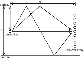
Assume that there are three eigenrays in the communication. Calculate the distance of each eigenray as follows. Assume that is the distance of the direct eigenray, is the distance of the eigenray reflected by surface only, and is the distance of the eigenray reflected by both surface and bottom. We have
| (1) |
| (2) |
| (3) |
where is the transmission distance, is the depth of the transmitter, is the depth of the receiver, is the height of the water column.
Transmission loss consists of the loss caused by pressure amplitude due to spherical spreading, denoted as , the loss caused by continuously transformed into heat, denoted as , the loss caused by the interaction with surface, denoted as , and the loss caused by the interaction with bottom, denoted as .
| (4) |
| (5) |
where =0.00000234, =0.00000338, is the salinity of the seawater, is the temperature of the seawater, is the frequency of the carrier-waves, is a relaxation frequency [20].
| (6) |
| (7) |
| (8) |
where
| (9) |
| (10) |
and is the density and sound speed in seawater, respectively. and is the density and sound speed in the seabed, respectively. is the reflection times with surface, is the reflection times with bottom. Let be the arrival time of eigenray , be the arrival time of eigenray , be the arrival time of eigenray . We have
| (11) |
As the time-varying features of the underwater acoustic channel should be taken into account, some statistical variables are introduced in the model. , representing the fading of individual eigenpath, are modeled as independent Rayleigh processes with unit mean and an exponential autocorrelation specified by the Doppler spreading. , representing the time jitter, are modeled as Gaussian processes with zero mean, variance and an exponential autocorrelation specified by a transducer position coherence time. In details, the and are fixed in the coherence time and altered out of the coherence time, namely, the and are same in the same data stream and different in the different data streams.
The noise in the model is considered as white noise, which denoted as .
The mathematical model of the underwater acoustic channel can be concluded as
| (12) |
where is the transmitted signal, is the received signal.
III Underwater acoustic communication based on QPSK and PTRM
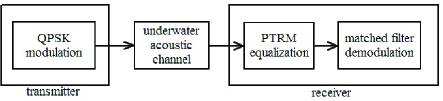
The schematic diagram of the underwater acoustic communication system based on QPSK modulation and PTRM equalization is showed in Fig. 2. The system consists of QPSK modulation, PTRM equalization and matched filter demodulation.
III-A QPSK Modulation
The main idea of the QPSK modulation is using the different initial phases to represent the different symbols [21]. The relationship between initial phases and corresponding symbols is showed in Table I. Gray coding has been considered for the QPSK symbols in Talbe I. The carrier-waves of the modulation can be either cosine signals or LFM signals.
| Initial phases | Symbols |
|---|---|
| 0 | 00 |
| 01 | |
| 11 | |
| 10 |
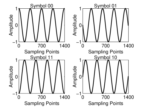
III-A1 QPSK Modulation Based on Cosine Carrier-waves
The four carrier-waves of the QPSK modulation based on cosine carrier-waves are showed in Fig. 3. The frequency of the cosine carrier-waves is 11.5kHz. In Fig. 3, we can find that the only difference among the four carrier-waves is the initial phases, showed in Table I.
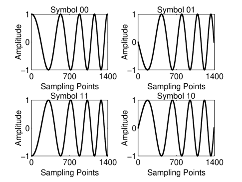
III-A2 QPSK Modulation Based on LFM Carrier-waves
The four carrier-waves of the QPSK modulation based on LFM are showed in Fig. 4. The frequency of the LFM carrier-waves is 5-18kHz. We can find that the difference between the LFM carrier-waves of different symbols is greater than that of cosine carrier-waves, which decreases BER of the communication system compared with the system using cosine wave.
III-B PTRM Equalization
PTRM is widely used in the underwater acoustic communication [1, 2, 4], which has advantage of matching the underwater acoustic channel automatically without any prior knowledge. PTRM is computational efficient, which contributes to implement a real-time communication. The schematics of PTRM is showed in Fig. 5.
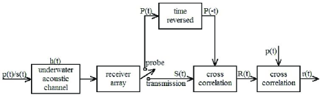
The transmission begins with sending a probe by the transmitter, denoted as . The probe is an LFM signal. After the multipathed arrivals finishing, the transmitter sends the data stream, denoted as . The received probe, denoting as , is transformed into the time reversed signal, denoted as . Then the is cross-correlated with the received data stream, which denoted as . The result of the cross-correlation is denoted as . Finally is cross-correlated with to get the equalization result, denoted as . is approximative to . From the foregoing statement, we have
| (13) |
| (14) |
where is the impulse response of the underwater acoustic channel, means cross-correlation.
| (15) |
| (16) |
To this end, we find is , due to the functions we got after PTRM equalization. Overlay of all the signals got by multi-hydrophone enhances the peak and suppresses the side lobes, as a result contribute to a better approximative function [8].
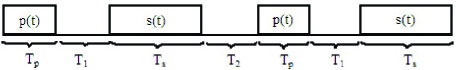
The frame structure of the transmitted signals is showed in Fig. 6. is the duration of the probe, is the duration of the guard delay after the probe, is the duration of the data stream, is the duration of the guard delay after the data stream, which is equal to . is a symbol period. As the channel property changes, it is necessary to insert a new probe after a period of transmission. In order to waiting for the channel to clear multipath arrivals, a guard delay is inserted between the data stream and the probe as well as between the probe and the data stream [8, 9].
III-C Matched Filter Demodulation
Matched filter is used to demodulate the signals after equalization. The demodulator at the receiver end stores the time reversed carrier-waves of all symbols as the reference. The signals after equalization are cross-correlated with every reference, one by one. The received signal will be demodulated as the symbol represented by the reference, which get the maximum peak in the cross-correlation, here, the maximum peak means the highest similarity. This method is different from the commonly used method that demodulates the received carrier-wave as the reference whose cross-correlation is greater than the decision threshold. Therefore, the larger difference between different carrier-waves can contribute to a lower BER. This demodulation method can relax the accuracy of the equalization and then decrease the complexity of the equalizer. Furthermore, the method is more appropriate in the complicated channels, where the received signal can not restore the transmitted signal very well by the equalization.
IV CWID modulation
As the quite severe distortion caused by the underwater acoustic channel, the received signal after equalization may not be similar to that of the corresponding reference, but more similar to the other reference, which leads to a wrong demodulation. The main idea of the CWID modulation is to increase the difference among different symbols’ carrier-waves. As the difference among different symbols’ carrier-waves increases, the received carrier-wave after equalization should be more similar to the corresponding reference, than the others, which contributes to getting a low BER.
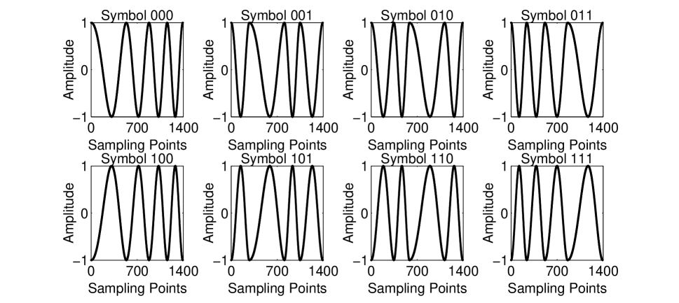
IV-A 4-CWID Modulation Based on LFM Carrier-waves
To show our idea, 4-CWID is used as an illustration. 4-CWID modulation based on LFM carrier-waves is to divide the LFM signal carrier-wave into pieces of carrier signals and reorganize the order of the pieces of carrier signals in order to construct the new carrier waveform. For illustration, we use a LFM carrier-wave with the symbol period =0.348ms, the bandwidth 5-18kHz for illustration. A LFM carrier-wave is showed in Fig. 7.
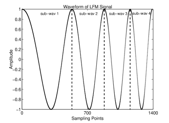
We split the waveform at every peak of the waveform, to obtain four pieces of sub-waveforms, marked sequentially from sub-wav 1 to sub-wav 4, as shown in Fig. 7. We reorganize the sequence of the sub-waveforms using the rule in Table II in order to get the largest difference between two different symbols. The main idea of getting the largest difference between two different symbols is that the same sub-wav will not appear in the same place of any two different carrier-waves, for example, sub-wav 1 is located in 1st place in the carrier-wave of symbol 00, then, sub-wav 1 should not be located in 1st place in the other carrier-waves.
| Symbols | 1st place | 2nd place | 3rd place | 4th place |
|---|---|---|---|---|
| 00 | sub-wav 1 | sub-wav 2 | sub-wav 3 | sub-wav 4 |
| 01 | sub-wav 2 | sub-wav 4 | sub-wav 1 | sub-wav 3 |
| 10 | sub-wav 3 | sub-wav 1 | sub-wav 4 | sub-wav 2 |
| 11 | sub-wav 4 | sub-wav 3 | sub-wav 2 | sub-wav 1 |
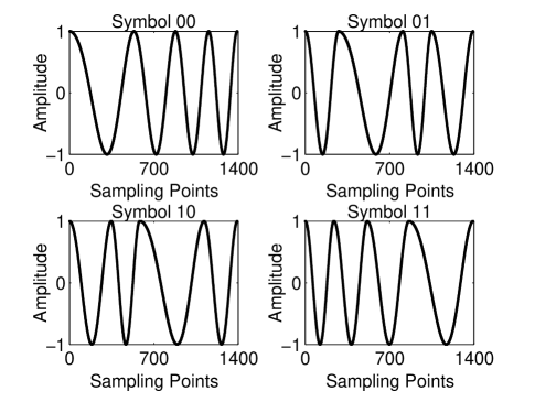
The 4-CWID carrier waveforms for different symbols are given in Fig. 8. Comparing the waveforms in Fig. 8 with those in Fig. 3 and Fig. 4, we see that the difference of the symbols become larger. The simulation results in the following part will show this contribute to the lower BER compared to cosine QPSK and LFM QPSK.
Remark 1: we can always find the special point, which make the sub-wavs connect each other smoothly, to split and reorganize the waveform in order to obtain the carrier-waves for CWID modulation, when the initial phase, the symbol period or the bandwidth of the LFM carrier-waves are changed. This means that the method is a general method.
IV-B 8-CWID Modulation Based on LFM Carrier-waves
Select the LFM signals with the initial phase 0 and as the basic carrier-waves for our 8-CWID modulation. Then carrier-waves can be obtained by splitting and reorganizing each carrier-wave as what we did in 4-CWID. The carrier-waves for 8-CWID are given in Fig. 9. The symbol period of the carrier-waves =0.348ms, the bandwidth of the carrier-waves is also 5-18kHz.
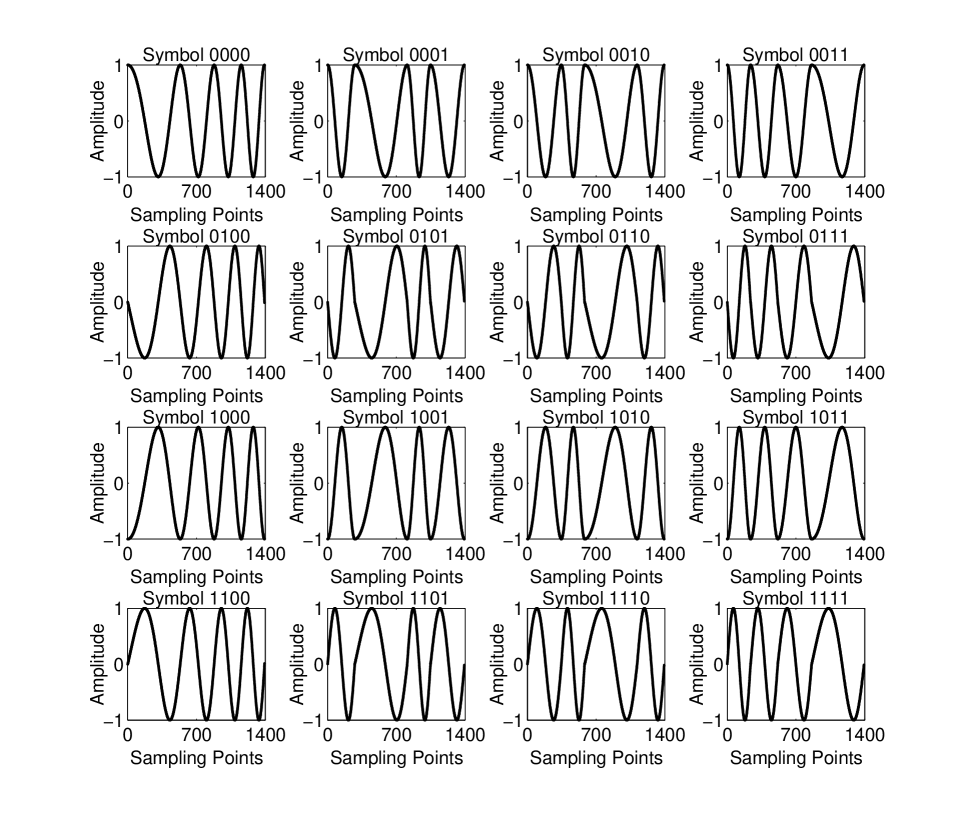
IV-C 16-CWID modulation based on LFM carrier-waves
Select the LFM signals with the initial phase 0, , and as the basic carrier-waves for our 16-CWID modulation. Then carrier-waves can be obtained by splitting and reorganizing the basic carrier-waves as what we did in 4-CWID and 8-CWID. The carrier-waves for 16-CWID are given in Fig. 10. The symbol period of the carrier-waves =0.348ms, the bandwidth of the carrier-waves is 5-18kHz.
Simulation will be done in the following section to show the result of the proposed modulation method.
V Simulation results
V-A Test of 4-CWID Modulation
Simulation was done to demonstrate the effectiveness of CWID modulation. In the simulation, the bandwidth of the LFM carrier-waves is 5-18kHz. The underwater acoustic channel has calm surface, smooth bottom, and 30 meters water depth. The sound speed in the entire propagation region is 1480m/s. The transmission distance between the transmitter and receiver is 650 meters. The transmitter hydrophone is deployed at the depth of 15 meters under water surface. The receiver array, which consists of 9 hydrophones, is ranged from 8.2 meter to 21.8 meter with a spacing interval of 1.7m. The spatial diversity provided by the array enhances the performance of PTRM equalization [8]. The transmitter and receiver are drifting, which causes the Doppler spreading and shifting. The drifting is decomposed into horizontal drifting and vertical drifting. The Doppler shifting is set as 10Hz, which equals to the relative horizontal drifting of 1.3m/s. The statistical variations of the fading are modeled as independent Rayleigh processes. The three coefficients of the Rayleigh process for three eigenrays are , and . The statistical variations of the time jitter are modeled as Gaussian processes with zero mean and variance , where means the 1-5cm vertical drifting. The noise is modeled as white noise. The data frame of the transmitted signals is showed as Fig. 6, where ms, ms since the longest multipath delay spread based on the first arrival is almost 100ms, ms is to make the probe and the data stream to be in a coherence time. The ideal synchronization is assumed in the simulation.
A testing ASCII code stream of ”New modulation method for wireless acoustic communication” are sent in first simulation. The results showed that the message can be decoded correctly in the receiver.
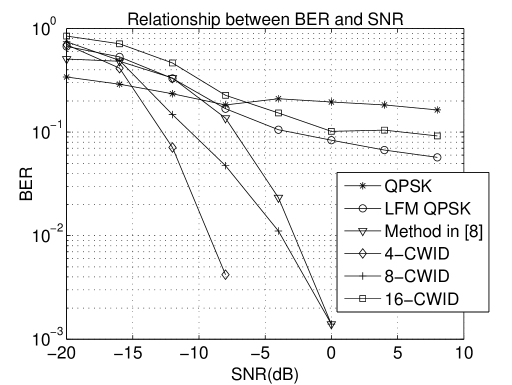
V-B Performance Comparison of Different Modulation Methods
The simulations of QPSK modulation based on cosine carrier-waves, LFM QPSK, the method proposed in [8], 4-CWID modulation, 8-CWID modulation, 16-CWID modulation are performed in this paper. The underwater acoustic channel properties and the data frame structure are the same as the case in 5.1. The simulation results are given in Table III. The SNR of the simulation showed in Table III is 8dB. The BER is got from transmitting 4000 random bits. The frequency of the cosine carrier-waves in the simulations is 11.5kHz. The LFM carrier-waves in the simulations is 5-18kHz. The method in [8] is designed by autocorrelating a Hamming windowed 5-18kHz LFM signal. The modulation method used in [8] can be considered as a kind of DBPSK modulation. The equalizations used in all simulations are PTRM.
| QPSK | LFM QPSK | Method in [8] | 4-CWID | 8-CWID | 16-CWID | |
|---|---|---|---|---|---|---|
| Equalization | PTRM | PTRM | PTRM | PTRM | PTRM | PTRM |
| Transmitting bit rate | 3.19kbit/s | 3.19kbit/s | 1.59kbit/s | 3.19kbit/s | 4.78kbit/s | 6.38kbit/s |
| Bandwidth | 11.5kHz | 5-18kHz | 5-18kHz | 5-18kHz | 5-18kHz | 5-18kHz |
| BER | 0.163 | 0.057 | 0 | 0 | 0 | 0.092 |
Figure 11 shows the result of performance comparison of different modulations under different SNR. The BER of the 4-CWID modulation is 0, when the SNR is larger than -4dB. The BER of the 8-CWID modulation and the method proposed in [8] are 0, when the SNR is larger than 4dB. The transmitting bit rate of 4-CWID is the same as these of the conventional QPSK and the LFM QPSK, whilst, the 4-CWID possesses much less BER than the conventional QPSK and the LFM QPSK. When the SNR is larger than -12dB, the proposed 8-CWID has higher transmitting bit rate and lower BER compared to conventional QPSK, LFM QPSK and method in [8]. All these show the superiority of the proposed method.
VI Conclusions
Due to the serious distortion caused by the underwater acoustic channel, it is very difficult to demodulate the information with high transmission rate and low BER. To solve this problem, we propose a novel CWID modulation to increase the difference of the carrier waveforms of different symbols. The larger difference of the carrier waveforms contributes to the lower BER. The CWID modulation is more appropriate for M-ary PSK modulation, which could achieve a higher transmitting bit rate with a low BER. The bandwidth efficiency is reduced in CWID modulation, due to the LFM carrier-waves are used. The reduction of the bandwidth efficiency brings the higher bit transmission rate and lower BER. The CWID modulation is more appropriate in complex channels. The bandwidth efficiency could be improved by optimizing the bandwidth of the LFM carrier-waves, which will be addressed in the future work. Comparison of the simulation results shows the superiority of the proposed methods. CWID modulation can also be used in other media of communications, for example, free space wireless communication.
References
- [1] M. Chitre, S. Shahabudeen, L. Freitag, and M. Stojanovic, “Recent advances in underwater acoustic communications and networking,” OCEANS 2008, pp. 1–10, 2008.
- [2] M. Chitre, S. Shahabudeen, and M. Stojanovic, “Underwater acoustic communications and networking: recent advances and future challenges,” Marine Technology Society Journal, vol. 42, pp. 103–116, Spring 2008.
- [3] S. P. Du, J. W. Yin, and J. Y. Hui, “Shallow water acoustic channel characteristics,” Science and Technology Innovation Herald, vol. 2.
- [4] M. Stojanovic and J. Preisig, “Underwater acoustic communication channels: propagation models and statistical characterization,” IEEE Communications Magazine, vol. 42, pp. 94–89, January 2009.
- [5] B. S. Li, S. L. Zhou, M. Stojanovic, L. Freitag, and P. Willett, “Multicarrier communication over underwater acoustic channels with nonuniform doppler shifts,” IEEE Journal of Oceanic Engineering, vol. 33, pp. 198–209, April 2008.
- [6] C. B. He, J. G. Huang, and Q. F. Zhang, “Development of high data-rate underwater acoustic communications,” Information Security and Communications Privacy, vol. 12, pp. 81–83, December 2010.
- [7] M. Stojanovic, J. Catipovic, and J. G. Proakis, “Adaptive multichannel combining and equalization for underwater acoustic communications,” Journal of the Acoustical Society of America, vol. 94, pp. 1621–1631, 1993.
- [8] D. Rouseff, D. R. Jackson, W. L. J. Fox, C. D. Jones, J. A. Ritcey, and D. R. Dowling, “Underwater acoustic communication by passive-phase conjugation: theory and experimental results,” IEEE Journal of Oceanic Engineering, vol. 26, pp. 821–830, October 2001.
- [9] J. W. Yin and J. Y. Hui, “Classified study on time reverse mirror in underwater acoustic communication,” Journal of System Simulation, vol. 20, pp. 2449–2453, May 2008.
- [10] V. Vadde, G. Indushree, and C. Sequeira, “Channel estimation and ber studies for an underwater acoustic ofdm system using time reversal mirror in shallow waters,” International Symposium on Ocean Electronics, pp. 241–247, 2011.
- [11] M. J. Lopez and A. C. Singer, “A dfe coefficient placement algorithm for sparse reverberant channels,” IEEE Transactions on Communications, vol. 49, pp. 1334–1338, August 2001.
- [12] X. Q. Zhao, J. Gu, M. Z. Tong, and T. L. Fang, “Novel adaptive dfe of underwater acoustic communication,” Journal of Military Communications Technology, vol. 31, pp. 29–35, 2010.
- [13] C. P. Shah, C. C. Tsimenidis, B. S. Sharif, and J. A. Neasham, “Low-complexity iterative receiver structure for time-varying frequency-selective shallow underwater acoustic channels using bicm-id: design and experimental results,” IEEE Journal of Oceanic Engineering, vol. 36, pp. 406–421, July 2011.
- [14] M. H. Lu, B. X. Zhang, and C. H. Wang, “Application of time reversal in underwater communication,” Acta Acustica, vol. 30, pp. 349–354, July 2005.
- [15] G. F. Edelmann, H. C. Song, S. Kim, W. S. Hodgkiss, W. A. Kuperman, and T. Akal, “Underwater acoustic communications using time reversal,” IEEE Journal of Oceanic Engineering, vol. 30, pp. 852–864, October 2005.
- [16] C. Keeser, B. J. Belzer, and T. R. Fischer, “Shallow underwater communication with passive phase conjugation and iterative demodulation and decoding,” 43rd Annual Conference on Information Sciences and Systems, pp. 907–912, 2009.
- [17] G. S. Zhang, J. M. Hovem, and H. F. Dong, “Experimental assessment of adaptive spatial combining for underwater acoustic communications,” 5th International Conference on Sensor Technologies and Applications, pp. 178–183, 2011.
- [18] H. C. Song, J. S. Kim, W. S. Hodgkiss, and J. H. Joo, “Crosstalk mitigation using adaptive time reversal,” Journal of the Acoustical Society of America, vol. 127, pp. 19–22, February 2010.
- [19] M. Chitre, “A high-frequency warm shallow water acoustic communications channel model and measurements,” Journal of the Acoustical Society of America, vol. 122, pp. 2580–2586, November 2007.
- [20] L. M. Brekhovskikh and Y. P. Lysanov, Fundamentals of Ocean Acoustics. Springer, 2002.
- [21] A. Goldsmith, Wireless Communications. Cambridge University Press, 2005.