Interpreting a nested Mach-Zehnder interferometer with classical optics
Abstract
In an recent work with the title “Asking Photons Where They Have Been”, Danan et al. experimentally demonstrate an intriguing behavior of photons in an interferometer [Phys. Rev. Lett. 111, 240402 (2013)]. In their words: “The photons tell us that they have been in the parts of the interferometer through which they could not pass.” They interpret the results using the two-state vector formalism of quantum theory and say that, although an explanation of the experimental results in terms of classical electromagnetic waves in the interferometer is possible (and they provide a partial description), it is not so intuitive. Here we present a more detailed classical description of their experimental results, showing that it is actually intuitive. The same description is valid for the quantum wave function of the photons propagating in the interferometer. In particular, we show that it is essential that the wave propagates through all parts of the interferometer to describe the experimental results. We hope that our work helps to give a deeper understanding of these interesting experimental results.
pacs:
03.65.Ta, 42.50.-p, 42.25.HzThe wave-particle duality is one of the most intriguing features of quantum mechanics. Quantum entities may behave as particles, as waves or as a strange combination of these possibilities. The affirmation that a quantum entity, such as an electron or a photon, is either a particle or a wave will always imply in a contradiction with experiments. So we can say that these entities are not particles nor waves, but very strange “things” that we do not understand in an intuitive way. This duality is explicitly manifested, for instance, in delayed choice experiments weeler78 ; jacques07 ; jacques08 and in quantum erasers scully91 ; herzog95 ; durr98 ; walborn02 . Recently delayed choice experiments were performed with quantum beam splitters roy12 ; auccaise12 ; tang12 ; peruzzo12 ; kaiser12 following the proposal of Ref. ionicioiu11 , showing even more intriguing behaviors.
In an interesting recent work, Danan et al. demonstrated another experiment in which the wave-particle duality plays an important role in the nonintuitive experimental results danan13 . This experiment was inspired on recent discussions about the past of a quantum particle in an interferometer vaidman13 . In the experimental arrangement, there is an inner interferometer in one of the arms of a large interferometer danan13 . They demonstrated that even when the inner interferometer is adjusted to produce destructive interference to the direction of the output port of the large interferometer, a tilting of some mirrors in the inner interferometer affects the average detection position of photons at the exit of the large interferometer. It is in this sense that the authors say that the photons “have been in the parts of the interferometer through which they could not pass”, since the dependence of the average detection position of the photons on the tilting of the mirrors shows that the photons have been in that arm, while the destructive interference in the inner interferometer should imply that the detected photons could not have passed through that arm. They also showed that the tilting of some other mirrors in this same arm of the large interferometer does not affect the average detection position of the photons at the exit. Danan et al. argue that this is a strange behavior, since the dependence on the tilting of some mirrors shows that the photons have been in that arm, while the independence on the tilting of the other mirrors would imply that they have not been in that arm. The authors provide an explanation using the two-state vector formalism of quantum theory aharonov64 ; aharonov90 and claim that this would be the most intuitive explanation of the phenomenon. They also discuss that an explanation in terms of classical electromagnetic waves is certainly possible, since the experiment was done with a strong laser beam, and provide a partial classical description of their results danan13 .
Here we provide a more detailed classical description of the experiments of Ref. danan13 , showing that it is actually intuitive. The same description is valid for the propagation of the wave function of the photons in the interferometer. In particular, we show that the wave (be it classical or quantum) must pass through both arms of the large interferometer to explain the experimental results, and that the fact that some mirrors affect the average photon detection position and some do not can be understood in terms of wave interference in a simple way. So we hope to give a contribution for a better understanding of the interesting results of Ref. danan13 with this work.
The experimental setup of Ref. danan13 is depicted in Fig. 1. A large interferometer, with entrance and exit beam splitters BS1 and BS4, has an inner (nested) interferometer with entrance and exit beam splitters BS2 and BS3 in one of its arms. The modulus of the reflection and transmission coefficients of BS1 and BS4 are and respectively, while the modulus of the reflection and transmission coefficients of BS2 and BS3 are . The mirrors , , , and vibrate around their horizontal axes, causing an oscillation of the vertical position of beam reaching the detector . The amplitude of this oscillation is much smaller than the beam diameter, and each mirror vibrates at a different frequency. The detector is a quad-cell photodetector and the registered signal is proportional to the difference between the number of photons detected in the upper and lower cells. The power spectrum of the measured signal contains peaks at the vibration frequencies of the mirrors whose angular positions affect the beam position at . Since the vibration frequencies are different, the influence of each mirror on the beam position at can be extracted from the data.
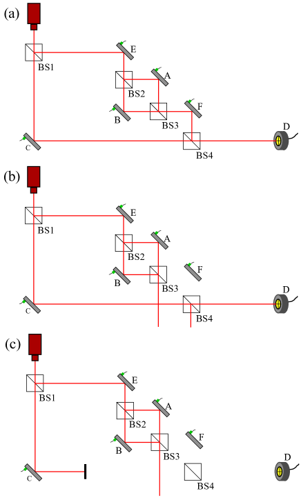
In the experimental situation of Fig. 1(a), the inner interferometer is aligned to generate constructive interference to the direction of mirror and the large interferometer is aligned to generate constructive interference to the direction of the detector . The experimental results show that the angular position of all mirrors , , , and affect the beam position at danan13 . The interesting and surprising result happens in the situation of Fig. 1(b), where the inner interferometer is aligned to generate destructive interference to the direction of mirror and the large interferometer is aligned to generate constructive interference to the direction of the detector . In this case the experimental results show that the angular positions of mirrors , and affect the beam position at , but the angular positions of mirrors and do not danan13 . This result seems to imply that the photons interact with mirrors and without interacting with mirrors and , what is, of course, impossible. In the experimental situation of Fig. 1(c), we have the same picture of Fig. 1(b) but the arm of mirror is blocked. In this case, the angular positions of none of the mirrors affect the beam position at danan13 .
Let us start our classical description of the experiments with the situation of Fig. 1(b), which is the most interesting one. The photons come from a Gaussian laser beam, such that their amplitude can be written as in a region close to its waist, where is the angular frequency of light and the modulus of the wavevector mandel . This amplitude may refer to a component of the electric or magnetic field of the beam, or to a component of the real or imaginary part of the Bialynicki-Birula–Sipe wave function of the photons in the beam birula94 ; sipe95 ; saldanha11 . If the experiment is performed with electrons, neutrons or other massive particles, the amplitude would be of the real or imaginary part of the Schrödinger wave function of these particles. So our treatment is valid for a classical electromagnetic wave and for quantum particles. Since the beam is in the paraxial regime, we can write its angular spectrum in terms of the components and of the wavevectors in the plane as the Fourier transform of the amplitude mandel , obtaining
| (1) |
with and the normalization factor of the corresponding wave. On this way, the beam amplitude can be written as
| (2) | |||||
in a decomposition in terms of the wavevectors, the paraxial regime meaning that and for all non-negligible values of mandel . From now on we will consider only the dependence of the beam state, , since the dependence does not change with the tilting of the mirrors.
Considering the direction as the propagation direction of the beam in each part of the interferometer for simplicity, if mirror is tilted, all wavevector components of the beam change with the reflection, such that the state of the beam after the reflection changes like , where refers to the state of the beam just after mirror and is proportional to the inclination amount. With this notation, the state of the beam just after mirror is
| (3) | |||||
In Fig. 2 we plot for different values of , , and . The vertical scale in the plots is arbitrary, but is the same in all plots. When , as in Fig. 2(a), no light goes to mirror . This is expected, since there is perfect destructive interference in the inner interferometer in this case. When , as in Fig. 2(b), there are almost no wavevectors whose components are close to 0, since there is an almost perfect destructive interference. But for wavevectors whose components are close to , we have some amplitude. This can be understood with the help of Fig. 3, that represents the beam states that come from mirrors () and () for exaggerated values of (positive) and (negative). When we compute for the graphs of Fig. 3, it is clear that a curve like Fig. 2(b) is obtained. When , as in Fig. 2(c), there is an inversion of the positive and negative parts of the amplitude. The amplitude maximum is proportional to . The values of and almost do not change the amplitude of the wave that is reflected by mirror , as can be seen comparing Figs. 2(b) and 2(d), that have the same values for and and different values for and . There is no perceptible difference between Figs. 2(b) and 2(d). The reason is that the angular tilting of mirrors and does not change the interference behavior of the inner interferometer, they only displace the wavevectors distribution of the beam after mirror . This displacement is very small, since in the plots of Fig. 2 and in the experiments of Ref. danan13 we have at least 3 orders of magnitude smaller than , such that they do not significantly influence the state of the beam after mirror .
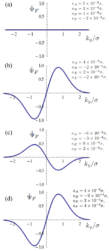

The beam that goes in the direction of the detector is a superposition of the beam that comes from mirror , with state , with the beam that comes from mirror , with state given by from Eq. (3). has a much smaller amplitude than due to the destructive interference in the inner interferometer. We can see that, when , as in Figs. 2(b) and 2(d), the superposition of with will increase the components of with positive and decrease the components with negative . This results in a up displacement of the resultant beam in the far field. When , as in Fig. 2(c), the opposite happens and we have a down displacement of the resultant beam in the far field. And when , as in Fig. 2(a), there is no displacement of the beam. Since and do not appreciably change the state from Eq. (3), they do not affect the resultant beam displacement in the far field.
The amplitude of the resultant beam in the position of the detector , considered to be in the far field, is proportional to the Fourier transform of the field amplitude in the interferometer, thus being proportional to the angular spectrum of the field at the exit of the interferometer mandel . So it is proportional to with the substitution , being a constant. The detector signal , being proportional to the difference between the light intensity in the upper and lower cells, is then proportional to the integral of the modulus squared of the angular spectrum of the resultant beam at the exit of the large interferometer for minus the same integral for . So we obtain
| (4) |
with
| (5) | |||
Since we are considering the limit , we can write
| (6) |
Substituting this approximation for the terms on the right side of Eq. (5), we obtain
| (7) | |||||
According to Eq. (1), the function from the above equation is symmetric around the maximum at . So, considering initially that we have , the integral of the first term on the right side of Eq. (4) from to cancels the second integral in this equation. In this case we have
| (8) |
Since the function is approximately constant on the above integral, we have
| (9) |
It is easy to see that the above equation is also valid for . So when the inner interferometer causes a destructive interference for the light propagation in the direction of mirror , as in Fig. 1(b), the vibrations of the mirrors , and make the signal to oscillate, while the vibrations of mirrors and do not. For this reason, if all mirrors vibrate at different frequencies, the power spectrum of the signal will present peaks at the vibration frequencies of mirrors , and , but not at the vibration frequencies of mirrors and . This is shown in the experiments of Ref. danan13 .
Considering now the situation depicted in Fig. 1(a), where there is constructive interference in the inner interferometer for the photons to go out in the direction of mirror , the calculations are basically the same. But now the angular spectrum of the resultant beam at the exit of the interferometer can be written as
| (10) | |||
Substituting in Eq. (4) in the limit and following the same steps as before in the calculation, we obtain
| (11) |
Now the vibrations of all mirrors make the signal oscillate, such that the vibration frequencies of all mirrors should be in the power spectrum. Since the tilting of mirrors and causes twice the beam displacement than a tilting of the same amount of the other mirrors, the power spectrum at the vibration frequencies of mirrors and should have a peak four times the value of the peaks at the vibration frequencies of mirrors , and , since the power spectrum is proportional to the square of the oscillation amplitude at each frequency. This is shown in the experiments of Ref. danan13 .
Considering the situation depicted in Fig. 1(c), all light that goes to the detector comes from mirror . We can see that, according to the plots in Fig. 2, the light intensity will be always (almost) symmetric around the origin, such that the vibration of the mirrors should not affect the signal and no peak should be observed in the power spectrum. This is also shown in the experiments of Ref. danan13 .
To summarize, we have presented a description of the experiments of Ref. danan13 using a classical description of light propagating in the interferometer. The same description is valid for the propagation of the wavefunction of quantum particles in the interferometer. This interpretation, that clearly shows that it is essential that the wave propagates through all parts of the interferometer to describe the experimental results, is complementary to the one using the two-state vector formalism of quantum theory aharonov64 ; aharonov90 presented in Ref. danan13 . We hope that our results can give more physical insight to the behavior of photons (and electromagnetic waves) in this interesting kind of interferometers.
This work was supported by the Brazilian agencies CNPq and PRPq/UFMG.
References
- (1) J. A. Wheeler, in Mathematical Foundations of Quantum Mechanics, edited by A. R. Marlow (Academic, New York, 1978).
- (2) V. Jacques et al., Science 315, 966 (2007).
- (3) V. Jacques et al., Phys. Rev. Lett. 100, 220402 (2008).
- (4) M. O. Scully, B. G. Englert, and H. Walther, Nature 351, 111 (1991).
- (5) T. J. Herzog, P. G. Kwiat, H. Weinfurter, and A. Zeilinger, Phys. Rev. Lett. 75, 3034 (1995).
- (6) S. Dürr, T. Nonn, and G. Rempe, Nature 395, 33 (1998).
- (7) S. P. Walborn, M. O. Terra Cunha, S. Pádua, and C. H. Monken, Phys. Rev. A 65, 033818 (2002).
- (8) S. S. Roy, A. Shukla, and T. S. Mahesh, Phys. Rev. A 85, 022109 (2012).
- (9) R. Auccaise et al., Phys. Rev. A 85, 032121 (2012).
- (10) J.-S. Tang et al., Nat. Photonics 6, 602 (2012).
- (11) A. Peruzzo et al., Science 338, 634 (2012).
- (12) F. Kaiser et al., Science 338, 637 (2012).
- (13) R. Ionicioiu and D. R. Terno, Phys. Rev. Lett. 107, 230406 (2011).
- (14) A. Danan, D. Farfurnik, S. Bar-Ad, and L. Vaidman, Phys. Rev. Lett. 111, 240402 (2013).
- (15) L. Vaidman, Phys. Rev. A 87, 052104 (2013); Z. H. Li, M. Al-Amri, and M. S. Zubairy, Phys. Rev. A 88, 046102 (2013); L. Vaidman, Phys. Rev. A 88, 046103 (2013).
- (16) Y. Aharonov, P.G. Bergmann, and J. L. Lebowitz, Phys. Rev. 134, B1410 (1964).
- (17) Y. Aharonov and L. Vaidman, Phys. Rev. A 41, 11 (1990).
- (18) I. Bialynicki-Birula. Acta Phys. Pol. A 86, 97 (1994).
- (19) J. E. Sipe, Phys. Rev. A 52, 1875 (1995).
- (20) P. L. Saldanha and C. H. Monken, New J. Phys. 13, 073015 (2011).
- (21) L. Mandel and E. Wolf, Optical Coherence and Quantum Optics (Cambridge University Press, New York, 1995).