Parametric amplification by coupled flux qubits.
Abstract
We report the parametric amplification of a microwave signal in a Kerr medium formed from superconducting qubits. Two mutually coupled flux qubits, embedded in the current antinode of a superconducting coplanar waveguide resonator, are used as a nonlinear element. Shared Josephson junctions provide the qubit-resonator coupling, resulting in a device with a measured gain of about 20 dB. We argue, that this arrangement represents a unit cell which can be straightforwardly extended to a quasi one-dimensional quantum metamaterial with a large tunable Kerr nonlinearity.
New developments in circuit quantum electrodynamics has resulted in the possibility of signal detection close to and even below the standard quantum limit. This work was motivated by microwave quantum engineering,You and Nori (2003); Grajcar et al. (2005a); Xiang et al. (2013) including quantum information processing devices.Reed et al. (2012); Fedorov et al. (2012) The sensitivity of cryogenic semiconductor amplifiers with reasonable power consumption in both the MHz Oukhanski et al. (2003) and GHz (commercially available) range are all currently above the quantum limit. At very low temperatures it is quite natural to use the parametric effect for amplification which adds no additional noise to the signal. In practice, a nonlinear superconducting oscillator can be used for this purpose.Kuzmin et al. (1983); Zagoskin et al. (2008) In this case, usually a nonlinearity of superconducting weak links Castellanos-Beltran et al. (2008); Yamamoto et al. (2008) is exploited. Very recently the squeezing of quantum noise and its measurement below the standard quantum limit was demonstrated.Mallet et al. (2011) These successful experiments have motivated the development of new parametric amplifiers based on Josephson junctions,Bergeal et al. (2010); Hatridge et al. (2011) DC squids,Abdo et al. (2009); Hatridge et al. (2011); Sundqvist et al. (2013) high kinetic inductance of weak links,Tholén et al. (2007) or disordered superconductors.Ho Eom et al. (2012) Superconducting qubits also exhibit a strong nonlinearity Il’ichev and Greenberg (2007) and therefore are good candidates for parameteric amplification.Savel’ev et al. (2012)
In this paper, we demonstrate parametric amplification exploiting the nonlinearity of a pair of superconducting flux qubits coupled to a coplanar waveguide resonator. These qubits represent a unit cell which can be easily extended to a one-dimensional array. Such an array can be considered as a medium with large Kerr nonlinearity.
Neglecting the interactions between the modes, a nonlinear oscillator can be described by the HamiltonianYurke and Buks (2006)
| (1) |
where is the reduced Planck constant, and are the creation and the annihilation operators, is the angular frequency of the -th mode of the oscillator, and is the Kerr constant, which is a measure of the nonlinearity in the system. The qubits contribute to the nonlinear inductance of the resonator per unit length according to
| (2) |
Then, the Kerr constant can be calculated byYurke and Buks (2006)
| (3) |
where sin, is the length of the resonator, the linear inductance of the resonator per unit length, the current flowing in the resonator, the critical current of the Josephson junction shared by the resonator and qubit, and are the Taylor coefficients characterizing the nonlinearity of the inductance. The Kerr constant can be determined for every nonlinear medium. In optics, the Kerr constants are very small while quantum information processing schemes require large ones. Even for a single superconducting qubit the Kerr constant is not small. It may be further enhanced by using ferromagnetically coupled qubits Grajcar et al. (2006); Smirnov . Moreover this constant can be tuned over a wide range, even from positive to negative large values.
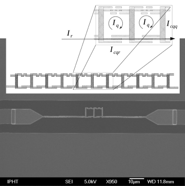
To demonstrate these features we fabricated two ferromagnetically coupled qubits embedded in a coplanar waveguide resonator. The niobium resonator is fabricated by e-beam lithography and dry etching the 200 nm thick film on a silicon substrate. The aluminium qubit structures are placed in the middle of the resonator and were prepared by the shadow evaporation technique (figure 1). To assure strong coupling between the resonator and the qubits (there are 6 Josephson junctions in each qubit), one of the Josephson junctions of each qubit, with critical current , is integrated within the centerline of the resonator. A bandwidth of the parametric amplifier is rather narrow, limited by a bandwidth of the resonator. However, the unit cell of two qubits can be extended to an array, forming a metamaterial in a coplanar waveguide (see figure 1), where the enhanced interaction of the microwaves with one unit cell caused by the multiple reflections of the microwave signal in the coupling capacitors of the resonator is substituted by the interaction with a large number of cells. By making use of such microwave waveguide instead of a resonator the bandwidth can be increased considerably.Ho Eom et al. (2012) The qubits in the array are weakly coupled by a shared large Josephson junction with a critical current . The coupling energy between adjacent qubits is Grajcar et al. (2005b)
| (4) |
where is the persistent current of the -th qubit, is the critical current of the coupling Josephson junction shared by adjacent qubits, and is the magnetic flux quantum. In the ground state the persistent currents in adjacent qubits flow through the coupling Josephson junction in the same direction in order to minimize the total energy of the two coupled qubits. By clever design one can use the shadow evaporation technique to twist the electrodes of the coupling Josephson junction in such a way that ferromagnetic coupling is achieved (see figure 1). For one qubit centered in a resonator the nonlinear inductance per unit length can be calculated from the relation Greenberg et al. (2002)
| (5) |
where is the delta function, and are the tunneling amplitude and the persistent current of the superconducting flux qubit, respectively, and the function is defined as
| (6) |
where and . The coefficient is obtained from the Taylor expansion of the nonlinear inductance .
Interactions with the measurement apparatus and the dissipative environment are modelled by making use of a standard model in the microwave region - by making use of the test and the dissipative ports (details see in Ref. Yurke and Buks, 2006 and references therein). Parametric amplification is achieved by strong pumping of the resonator at a frequency . The pump frequency is mixed with a weak signal of frequency by the nonlinear element, producing additional signals with angular frequencies and (idler signal). In other words, two photons from the pump with angular frequency transform into two photons with angular frequencies and , while the energy is conserved. For strong pumping and in absence of fluctuations the system can be described by the classical variables , , and the average number of photons in the resonatorYurke and Buks (2006)
| (7) | |||||
where is the average number of photons coming to resonator from input port in a time interval . The amplitude of the transmission coefficient of the resonator, which can be measured directly by a network analyzer and is given by the ratio

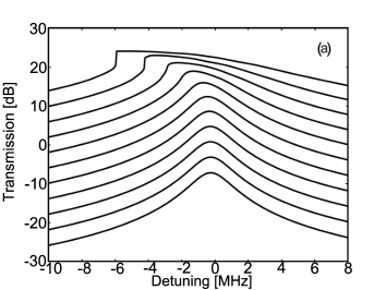
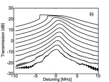
We performed several measurements in a dilution refrigerator with base temperature of 10 mK, where a biasing coil was integrated into the sample holder to apply a magnetic flux. First, we characterized the resonator by measuring its transmission and varying the input power and frequency (figure 2). The resonance curve exhibits typical behavior of a Duffing oscillator.Kovacic and Brennan (2011) From the low input power spectra, we extract the resonance frequency of the third harmonic and its loaded quality factor, which have the values: GHz and , respectively. From the theoretical model,Yurke and Buks (2006) we determined the ratio between the Kerr constant and the nonlinear dissipation , which is calculated to be -3.5 for . This kind of analysis is not possible for , because as one can see from figure 3, for low input power the transmission curve is bent towards the higher frequencies and then, for higher powers, the curve bends towards lower frequencies. We can model this behavior by a current (power) dependent Kerr constant
| (8) |
where corresponds to the fourth order term in the Taylor series given by equation (2). From qubit spectroscopy, we obtained the parameters that allow us to determine and subsequently and . We investigated the detuning of the resonance frequency at different values of the applied magnetic field (figure 3). We chose two working points: magnetic flux , where the energy gap between the qubit’s energy levels is large, and , which corresponds to the qubits degeneracy point with an energy gap equal to the tunnelling amplitude . The detuning of the resonance frequency of the resonator is inversely proportional to the energy gapGrajcar et al. (2005a); Omelyanchouk et al. (2010) and it is maximal at .
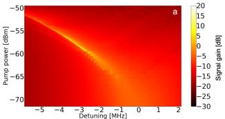
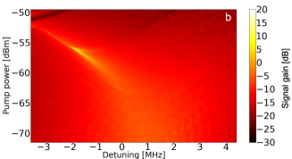
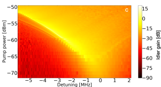
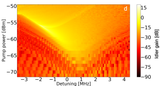
The gain of the parametric amplifier was investigated in the following way: the transmission was measured at the signal frequency whilst keeping its amplitude constant. The amplitude of the pump was greater than the amplitude of the signal, while simultaneously sweeping the amplitude and frequency of the pump. The frequency difference between the signal and the pump was 10 kHz (approx. 1 of the bandwidth of our resonator). The gain of the parametric amplifier depends on the frequency and the power of the pump (figure 4). The magnetic flux applied to the qubits only slightly alters the resulting gain of both the signal and the idler, while the maximal gain is 20 dB. The main difference between these two cases is the presence of two “high amplification branches” at instead of only one present at and a periodic pattern of the gain depending on the bias flux (see figure 4). These peculiarities may be a consequence of the quantum nature of the superconducting qubit (“Landau - Zenner beam splitting” at the qubit degeneracy point Shevchenko et al. (2008)) and/or the modulation instability characteristic for wave propagation in a nonlinear dispersive media.Ostrovskiy (1966); Agrawal (1987) The modulation instability has recently been investigated in optical metamaterials taking into account both cubic and quintic nonlinearities.Saha and Sarma (2013) It has been predicted that a combined effect of cubic–-quintic nonlinearity increases the modulation instability gain. Our experimental results show that the quintic nonlinearity, which is characterized by higher order Kerr constant , cannot be neglected for strongly coupled superconducting qubits. Moreover, the shape of the idler gain is remarkably similar to the modulation instability gain shown in Refs. Agrawal, 1987; Saha and Sarma, 2013. A more detailed theoretical quantum analysis of parametric amplification is required in order to clarify this effect.
| max. gain [dB] | reference | ||
| - | 30 | [Eichler et al., 2011] | |
| - | 22 | [Tholén et al., 2009] | |
| - | 28 | [Beltran and Lehnert, 2007] | |
| 20 | this paper |
In summary, we designed a parametric amplifier based on a superconducting coplanar waveguide resonator with a pair of integrated qubits serving as the nonlinear element. In contrast to other publications (see table,1) the Kerr constant of our system is -tunable and several orders of magnitude higher. Our amplifier achieves a maximal gain of 20 dB, which is comparable to the gain of similar superconducting parametric amplifiers.Ho Eom et al. (2012); Tholén et al. (2007); Abdo et al. (2009) However, the experiments reveal two unknown features, namely two “branches” of high amplification of the idler signal and in the case of a bias flux of a periodical pattern of the gain dependent on the flux itself.
The research leading to these results has received funding from the European Community’s Seventh Framework Programme (FP7/2007-2013) under Grant No. 270843 (iQIT). This work was also supported by the Slovak Research and Development Agency under the contract APVV-0515-10 (former projects No. VVCE-0058-07, APVV-0432-07) and LPP-0159-09. The authors gratefully acknowledge the financial support of the EU through the ERDF OP RD, Project CE QUTE metaQUTE.
References
- You and Nori (2003) J. Q. You and F. Nori, Phys. Rev. B 68, 064509 (2003), http://link.aps.org/doi/10.1103/PhysRevB.68.064509.
- Grajcar et al. (2005a) M. Grajcar, A. Izmalkov, and E. Il’ichev, Phys. Rev. B 71, 144501 (2005a), http://link.aps.org/doi/10.1103/PhysRevB.71.144501.
- Xiang et al. (2013) Z.-L. Xiang, S. Ashhab, J. Q. You, and F. Nori, Rev. Mod. Phys. 85, 623 (2013), http://link.aps.org/doi/10.1103/RevModPhys.85.623.
- Reed et al. (2012) M. D. Reed, L. DiCarlo, S. E. Nigg, L. S. andL. Frunzio, S. M. Girvin, and R. J. Schoelkopf, Nature 482, 382385 (2012).
- Fedorov et al. (2012) A. Fedorov, L. Steffen, M. Baur, M. P. da Silva, and A. Wallraff, Nature 481, 170172 (2012).
- Oukhanski et al. (2003) N. Oukhanski, M. Grajcar, E. Il’ichev, and H.-G. Meyer, Review of Scientific Instruments 74, 1145 (2003), http://scitation.aip.org/content/aip/journal/rsi/74/2/10.1063%/1.1532539.
- Kuzmin et al. (1983) L. S. Kuzmin, K. K. L. i k h a r e v, V. . Migulin, and A. B. Z. o r i n, IEEE TRANSACTIONS ON MAGNETICS MAG-19, 618 (1983).
- Zagoskin et al. (2008) A. M. Zagoskin, E. Il’ichev, M. W. McCutcheon, J. F. Young, and F. Nori, Phys. Rev. Lett. 101, 253602 (2008), http://link.aps.org/doi/10.1103/PhysRevLett.101.253602.
- Castellanos-Beltran et al. (2008) M. A. Castellanos-Beltran, K. D. Irwin, G. C. Hilton, L. R. Vale, and K. W. Lehnert, Nature Physics 4, 929 (2008).
- Yamamoto et al. (2008) T. Yamamoto, K. Inomata, M. Watanabe, K. Matsuba, T. Miyazaki, Y. N. W. D. Olive and, and J. S. Tsai, Appl. Phys. Lett. 93, 042510 (2008).
- Mallet et al. (2011) F. Mallet, M. A. Castellanos-Beltran, H. S. Ku, S. Glancy, E. Knill, K. D. Irwin, G. C. Hilton, L. R. Vale, and K. W. Lehnert, Phys. Rev. Lett. 106, 220502 (2011), http://link.aps.org/doi/10.1103/PhysRevLett.106.220502.
- Bergeal et al. (2010) N. Bergeal, F. Schackhert, M. Metcalfe, R. Vijay, V. E. Manucharyan, L. Frunzio, D. E. Prober, R. J. Schoelkopf, S. M. Girvin, and M. H. Devoret, Nature 465, 64 (2010).
- Hatridge et al. (2011) M. Hatridge, R. Vijay, D. H. Slichter, J. Clarke, and I. Siddiqi, Phys. Rev. B 83, 134501 (2011), http://link.aps.org/doi/10.1103/PhysRevB.83.134501.
- Abdo et al. (2009) B. Abdo, O. Suchoi, E. Segev, O. Shtempluck, M. Blencowe, and E. Buks, Europhys. Lett. 85, 68001 (2009), http://stacks.iop.org/0295-5075/85/i=6/a=68001.
- Sundqvist et al. (2013) K. M. Sundqvist, S. Kintas, M. Simoen, P. Krantz, M. Sandberg, C. M. Wilson, and P. Delsing, Applied Physics Letters 103, 102603 (2013), http://scitation.aip.org/content/aip/journal/apl/103/10/10.10%63/1.4819881.
- Tholén et al. (2007) E. A. Tholén, A. Ergül, E. M. Doherty, F. M. Weber, F. Grégis, and D. B. Haviland, Applied Physics Letters 90, 253509 (pages 3) (2007), http://link.aip.org/link/?APL/90/253509/1.
- Ho Eom et al. (2012) B. Ho Eom, P. K. Day, H. G. LeDuc, and J. Zmuidzinas, Nature Physiscs 8, 623 (2012).
- Il’ichev and Greenberg (2007) E. Il’ichev and Y. S. Greenberg, Europhys. Lett. 77, 58005 (2007), http://stacks.iop.org/0295-5075/77/i=5/a=58005.
- Savel’ev et al. (2012) S. Savel’ev, A. M. Zagoskin, A. L. Rakhmanov, A. N. Omelyanchouk, Z. Washington, and F. Nori, Phys. Rev. A 85, 013811 (2012), http://link.aps.org/doi/10.1103/PhysRevA.85.013811.
- Yurke and Buks (2006) B. Yurke and E. Buks, J. Lightwave Technol. 24, 5054 (2006), http://jlt.osa.org/abstract.cfm?URI=jlt-24-12-5054.
- Grajcar et al. (2006) M. Grajcar, A. Izmalkov, S. H. W. van der Ploeg, S. Linzen, T. Plecenik, T. Wagner, U. Hübner, E. Il’ichev, H.-G. Meyer, A. Y. Smirnov, et al., Phys. Rev. Lett. 96, 047006 (2006), http://link.aps.org/doi/10.1103/PhysRevLett.96.047006.
- (22) A. Y. Smirnov, Signature of entangled eigenstates in the magnetic response of two coupled flux qubits, eprint arXiv:cond-mat/0312635.
- Grajcar et al. (2005b) M. Grajcar, A. Izmalkov, S. H. W. van der Ploeg, S. Linzen, E. Il’ichev, T. Wagner, U. Hübner, H.-G. Meyer, A. Maassen van den Brink, S. Uchaikin, et al., Phys. Rev. B 72, 020503 (2005b), http://link.aps.org/doi/10.1103/PhysRevB.72.020503.
- Greenberg et al. (2002) Y. S. Greenberg, A. Izmalkov, M. Grajcar, E. Il’ichev, W. Krech, H.-G. Meyer, M. H. S. Amin, and A. M. van den Brink, Phys. Rev. B 66, 214525 (pages 6) (2002), http://link.aps.org/abstract/PRB/v66/e214525.
- Kovacic and Brennan (2011) I. Kovacic and M. J. Brennan, eds., The Duffing Equation. Nonlinear Oscillators and their Behaviour. (John Wiley & Sons, Ltd., 2011).
- Omelyanchouk et al. (2010) A. N. Omelyanchouk, S. N. Shevchenko, Y. S. Greenberg, O. Astafiev, and E. Il’ichev, Low Temperature Physics 36, 893 (2010), http://link.aip.org/link/?LTP/36/893/1.
- Shevchenko et al. (2008) S. N. Shevchenko, S. H. W. van der Ploeg, M. Grajcar, E. Il’ichev, A. N. Omelyanchouk, and H.-G. Meyer, Phys. Rev. B 78, 174527 (2008), http://link.aps.org/doi/10.1103/PhysRevB.78.174527.
- Ostrovskiy (1966) L. A. Ostrovskiy, Zh. Eksp. Teor. Fiz 51, 1189 (1966).
- Agrawal (1987) G. P. Agrawal, Phys. Rev. Lett. 59, 880 (1987), http://link.aps.org/doi/10.1103/PhysRevLett.59.880.
- Saha and Sarma (2013) M. Saha and A. K. Sarma, Optics Communications 291, 321 (2013), ISSN 0030-4018, http://www.sciencedirect.com/science/article/pii/S00304018120%12837.
- Eichler et al. (2011) C. Eichler, D. Bozyigit, C. Lang, M. Baur, L. Steffen, J. M. Fink, S. Filipp, and A. Wallraff, Phys. Rev. Lett. 107, 113601 (2011), http://link.aps.org/doi/10.1103/PhysRevLett.107.113601.
- Tholén et al. (2009) E. A. Tholén, A. Ergï¿œl, K. Stannigel, C. Hutter, and D. B. Haviland, Physica Scripta 2009, 014019 (2009), http://stacks.iop.org/1402-4896/2009/i=T137/a=014019.
- Beltran and Lehnert (2007) M. A. C. Beltran and K. W. Lehnert, Appl. Phys. Lett. 91, 083509 (2007), http://dx.doi.org/10.1063/1.2773988.