Stable optical spring in aLIGO detector with unbalanced arms and in Michelson-Sagnac interferometer
Abstract
Optical rigidity in aLIGO gravitational-wave detector, operated on dark port regime, is unstable. We show that the same interferometer with excluded symmetric mechanical mode but with unbalanced arms allows to get stable optical spring for antisymmetric mechanical mode. Arm detuning necessary to get stability is shown to be a small one — it corresponds to small power in signal port. We show that stable optical spring may be also obtained in Michelson-Sagnac interferometer with both power and signal recycling mirrors and unbalanced arms.
I Introduction
Ground-based gravitational waves antennas form worldwide net of large-scale detectors like LIGO Abbott et al. (2009); Harry and the LIGO Scientific Collaboration (2010), VIRGO Accadia et al. (2012) and GEO Grote (2010). Extremely high sensitivity of this detectors is limited by noises of different nature. In the low frequency range (around Hz) the gravity-gradient (Newtonian) noise prevails, below Hz — seismic ones, at middle frequencies ( Hz) thermal noises dominate and in high frequency range (over Hz) photon shot noise makes main contribution. Next generation of gravitational wave antennas (Advanced LIGO or aLIGO Harry and the LIGO Scientific Collaboration (2010), Advanced VIRGO adv (2009)) and also third generation detectors (such as Einstein Telescope Punturo et al. (2010); Hild et al. (2011), GEO-HF B. Willke et al. (2006) and KAGRA K. Somiya (2012)) promise by compensation and suppression of thermal and other noises to achieve sensitivity of Standard Quantum Limit (SQL) V.B. Braginsky (1968); V.B. Braginsky and Yu.I. Vorontsov (1975); V.B. Braginsky, Yu.I. Vorontsov and F.Ya. Khalili (1977); V.B. Braginsky and F.Ya. Khalili (1992) for continuous measurement defined only by quantum noise. SQL is the optimal combination of two noises of quantum nature: fluctuations of light pressure caused by random photon number falling onto mirror’s surface and photon counting noise.
Possible way to overcome the SQL is the usage of optical rigidity (optical spring effect) V.B. Braginsky and I.I.Minakova (1967); Braginsky and Manukin (1967); V.B. Braginskii (1972); V.B. Braginsky and F.Ya. Khalili (1992). Recall optical rigidity appears in a detuned Fabry-Perot interferometer — the circulating power and consequently the radiation pressure became dependent on the distance between the mirrors. It has been shown Braginsky and Khalili (1999); F.Ya. Khalili (2001); A. Buonanno and Y. Chen (2001, 2002); V.I. Lazebny and S.P. Vyatchanin (2005); F.Ya. Khalili, V.I. Lazebny and S.P. Vyatchanin (2006); Nishizawa et al. (2007); Rakhmanov (2000) that gravitational wave detectors using optical springs exhibit sensitivity below the SQL.
In case of single pump an interferometer utilizing optical rigidity has two subsystems: a mechanical one and an optical one. Interaction between them gives birth to two eigen modes each of which is characterized by its own resonance frequency and damping. For description of evolution one can make transfer from the conventional coordinates to eigen ones and consider the evolution of the system as evolution of these (normal) oscillators Rakhubovsky and Vyatchanin (2012).
Dynamics of complex system such as aLIGO detector can be considered on the basis of more simpler and well studied system — Fabry-Pero resonator. Such equivalence is termed scaling law A. Buonanno and Y. Chen (2003). Fabry-Pero resonator with only one optical spring is always unstable because a single pump introduces either positive spring with negative damping or negative spring with positive damping V.B. Braginsky and I.I.Minakova (1967); Braginsky and Manukin (1967); V.B. Braginskii (1972); Braginsky and Khalili (1999). The obvious ways to avoid instabilities is implementation of feedback A. Buonanno and Y. Chen (2002). Another way is utilization of additional pump H. Rehbein, H. Müller-Ebhardt, K. Somiya, S.L. Danilishin, C. Li, R. Schnabel, K. Danzmann, and Y. Chen (2008); Rakhubovsky et al. (2011), which has been investigated in details and proven experimentally with mirror of gram-scale T. Corbitt, Y. Chen, E. Innerhofer, H. Müller-Ebhardt, D.Ottaway, H. Rehbein, D. Sigg, S. Whitcomb, C. Wipf, and N. Mavalvala (2007).
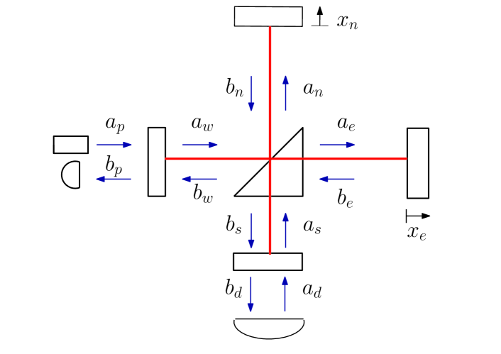
DC readout, planned in aLIGO, means introduction of small detuning of arm length. Recall that Michelson interferometer with balanced Fabry-Perot (FP) cavities in arms with power and signal recycling mirrors (aLIGO configuration, see Fig. 2) operating in dark port regime possesses symmetric and antisymmetric modes, laser pumps symmetric mode and no mean intensity appears in signal (dark) port through signal recycling mirror (SRM). In case of slightly detuned arms small mean intensity appears in signal port. This intensity is used as very stable local oscillator.
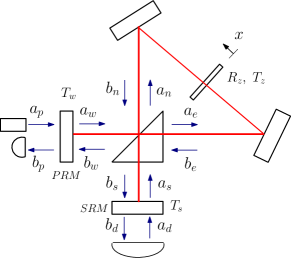
The natural question is what arbitrary (not small) detuning in arms may give for stability. This question became interesting especially after paper of Tarabrin with colleagues S. P. Tarabrin, H. Kaufer, F. Ya. Khalili, R. Schnabel and K. Hammerer (2013) demonstrated possibility of stable optical spring in Michelson-Sagnac interferometer with movable membrane D. Friedrich et al. (2011); K. Yamamoto et al. (2010); A. Xuereb, R. Schnabel, and K. Hammerer (2011). Analyzed interferometer with signal recycling mirror (SRM) but without power recycling (PRM) was pumped through power port S. P. Tarabrin, H. Kaufer, F. Ya. Khalili, R. Schnabel and K. Hammerer (2013) — similar configuration is shown on Fig. 2 (but with PRM). However, stability of optical spring was shown for relatively large detuning — it means relatively large power in signal port, which is not convenient in experiment. Operation far from dark port regime additionally creates the problem of laser noises leaking into signal port — it makes difficult application of these results to GW detector.
The aim of this paper is to analyze and to demonstrate stable optical rigidity in aLIGO (or Michelson-Sagnac interferometer with PRM and SRM) a) pumped throwgh PRM, b) with arm detuning as small as possible (hence, small output power throwgh SRM). This result may be applied not only to large-scale gravitational-wave detectors Khalili et al. (2010) but also to other optomechanical systems like micromembranes inside optical cavities Thompson et al. (2008) (see Fig. 2), microtoroids Verhagen et al. (2012), optomechanical crystals Eichenfield et al. (2009), pulse-pumped optomechanical cavities Vanner et al. (2011). In spite of the fact that optical rigidity, introduced into micromechanical oscillators, is relatively small as compared with intrinsic one D. Friedrich et al. (2011), it may be used for control and manipulation of its dynamics.
II Description of model
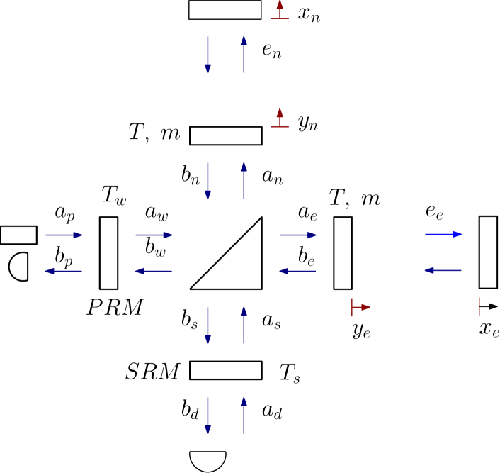
We consider a gravitational-wave antenna aLIGO shown on Fig. 2, amplitude transmittances of SRM and PRM are and correspondingly. Antenna consists of a Michelson interferometer with additional mirrors forming Fabry-Perot (FP) cavities with mean distance between mirrors in arms which is much larger than distances between beam splitter and SRM or PRM. Input mirrors have amplitude transmittance and masses , end mirrors have the same masses and are completely reflective. Input and end mirrors in arms may move as free masses. We assume that all mirrors are lossless. The interferometer is pumped by laser through PRM.
Recall dynamics of pure balanced interferometer (i.e. identical FP cavities in arms tuned in resonance with pumped laser) can be split into two modes: namely symmetric and antisymmetric ones. Each mode is characterized by optical detuning () and decay rate () dependent on displacement and transparency of PRM for symmetric mode (SRM for antisymmetric one correspondingly). Here and below we denote detuning as difference between laser frequency and eigen frequencies of symmetric and antisymmetric modes:
| (1) |
(In aLIGO PRM detuning is assumed to be zero, however, below we reserve possibility to vary it.) The optical fields in the modes represent difference () and sum () of the fields in arms respectively and carry information about difference () and sum () between lengths of arm cavities:
| (2) | ||||
| (3) |
(see notations on Fig, 2). In turn, light pressure force may be devided into two part: fluctuational one responsible for fluctuational back action and regular part creating optical spring Danilishin and Khalili (2012). Below we analyze the simplified case when sum mechanical displacement is fixed (for example, by feedback):
| (4) |
When FP cavities in arms are detuned by symmetric and antisymmetric modes became coupled with each other. In this case detunings (1) and decay rates refer to partial modes. As a result, the system is described by linear set of equations for Fourier components of fields and displacement :
| (5a) | ||||
| (5b) | ||||
| (5c) | ||||
| (5d) | ||||
| (5e) | ||||
| (5f) | ||||
Here is Plank constant, is wave vector corresponding to laser wave frequency , is speed of light. are mean complex amplitudes of symmetric and antisymmetric modes (excited by pump laser), is power circulating in symmetric mode. The right parts () in set describes zero fluctuational fields incoming into interferometer through PRM and SRM. Details of notations and derivation are presented in Appendix A.
In spite of the fact that set (5) is not convenient for analysis of sensitivity (because we have to recalculate fields into output field in signal port), however, it is convenient for optical rigidity analysis.
Following oscillations theory advises we rewrite (5) introducing normal coordinates for e.m. fields and new (complex) eigen values :
| (6a) | ||||
| (6b) | ||||
| (6c) | ||||
| (6d) | ||||
| (6e) | ||||
| (6f) | ||||
| (6g) | ||||
Here we introduce the following notations:
| (7) | ||||
| (8) | ||||
| (9) |
In set (6) we omit fluctuational fields in right parts as we are interesting in dynamic behavior of system, i.e. in eigen values of determinant.
After substitution ) characteristic equation of set (6) may be written in form:
| (10) |
where we introduce the following notations:
| (11a) | ||||
| (11b) | ||||
| (11c) | ||||
| (11d) | ||||
| (11e) | ||||
The form of equation (10) is the same as for double pumped optical spring H. Rehbein, H. Müller-Ebhardt, K. Somiya, S.L. Danilishin, C. Li, R. Schnabel, K. Danzmann, and Y. Chen (2008); Rakhubovsky et al. (2011): two fractions ( and ) are similar to two optical springs created in two optical modes pumped separately. This analogy has physical sense — for imbalanced interferometer one pump excites two normal modes. This analogy became more obvious when relaxation rates of symmetric and antisymmetric modes are equal (). In this case the values and are pure real and . Then characteristic equation takes the following form:
| (12) |
III Analysis
Eq.(10) may be written in form convenient for further approximation
| (14) | ||||
| (15) | ||||
| (16) | ||||
| (17) |
Underline that Eq. (14) is still exact characteristic equation. Mathematically its left part is a polynomial of -th degree relatively variable . Its solution provides set of eigenvalues , its imaginary parts describe eigen frequencies whereas real parts – relaxation rates (positive one corresponds to instability). It is not difficult task for numerical solution of (14) using contemporary mathematical packets. However, analysis based on numeric calculations is not simple because there is set of parameters () which may be varied.
In theoretical analysis below we make following assumptions:
-
•
Interferometer is pumped through PRM.
-
•
Arm detuning is small: .
-
•
Initial relaxation rates are small: .
Then Eq. (14) may be solved by iteration method considering term as main term (in zero approximation roots are ), whereas account of term of first order of smallness gives next iteration . We can do that because coefficients (5f, 9), hence, (11e) and the ”additional” pump (11c). It means that is much smaller than the ”main” pump and we may apply iteration method.
Zero order iteration.
The solution of equation is following:
| (18) | ||||
| (19) |
Note that in case of zero arm detuning () these roots was found earlier F.Ya. Khalili (2001); V.I. Lazebny and S.P. Vyatchanin (2005); F.Ya. Khalili, V.I. Lazebny and S.P. Vyatchanin (2006) (for example, the case of corresponds to double resonance regime) and formulas above may be considered as generalization for small .
Solution of equation gives obvious roots:
| (20) |
So in zero order approximation we have roots , among them the roots correspond to instability (). Now zero order part of determinant may be written as
| (21) | ||||
First order of iteration.
Our aim is to choose such parameters which make stable next iteration root , i.e.
| (22) |
We divide (14) by (taking into account (21)) and put in . So we get next iteration of characteristic equation:
| (23) | ||||
| (24) |
We may keep in mind as a constant of first order of smallness.
Below we put , it is this choose of that provides stability with minimal arm detuning . This choice has physical sense corresponding to known scheme of laser cooling (see, for example Vyatchanin (1977); F. Marquardt, A.A.Clerk, S.M. Girvin (2008)). Indeed, let FP cavity, which one mirror is a mechanical oscillator with frequency , is pumped by laser with frequency less than cavity frequency by detuned from resonance. In this case positive damping will be created for movement of mechanical oscillator (optical rigidity is negligibly small).
One may write down solution of (23) in analytical form
| (25) | ||||
Analysis shows that . Then at condition
| (26) |
the second term in (25) is practically imaginary and its real part is small enough. Then the condition stability may be approximately formulated as
| (27) |
This conditions give an estimation for minimal value of arm detuning:
| (28) | ||||
The formula (28) is confirmed by numerical calculations presented in the following section.
Important that in order to fulfill condition (28) one has to provide relatively small arm detuning . Here we made an assumption that depend weakly on a value of . So we put correspondingly when doing numerical estimations, because otherwise (28) turns into non-trivial equation for (we did this approximation only estimating value of , other numerical calculations stay exact).
| Detuning of symmetric mode () | -23.0 Hz |
|---|---|
| Detuning of antisymmetric mode () | 42.4 Hz |
| Decay rate of symmetric mode () | 1.5 Hz (3.0 Hz) |
| Decay rate of antisymmetric mode () | 0.3 Hz (3.0 Hz) |
| Test mass (m) | 40 kg |
| Arm length (L) | 4 km |
| Circulating power () | 24 kW |
| Arm detuning () | 1.51 Hz (4.6 Hz) |
IV Numerical estimations
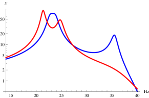
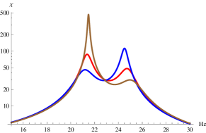
Numerical estimations can serve as an examination of our theory. We can solve (14) numerically substituting realistic parameters. We chose the parameters for aLIGO interferometer presented in Table 1 Advanced LIGO reference design (2005). We consider two cases — when and when . In a table values in brackets mean second case. Our analysis also gives an estimation for output power (as we know in aLIGO reference design output power should be about ). It is a good result because we don’t want to obtain big laser power on a photodetector. Importantly that here we chose operating frequency about 30 Hz. This value differs from aLIGO one — 100 Hz. We made it because in our case power-recycling mirror is detuned from resonance. From this fact follows that the circulating power ( 24 kW) is less than in aLIGO ( 800 kW). Susceptibility curves for this parameters are represented on a Fig. 5. Numerical solution of (14) gives us a set of eigenvalues with negative real parts — it means stability. Important that numerical egenvalues are in good agreement with analytical estimates. In addition we checked our analysis numerically by Routh – Hurwitz stability criterion. It showed stability for parameters predicted by our theory.
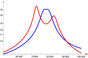
We also did the same analysis for Michelson-Sagnac interferometer. For such system we chose realistic parameters presented in Table 2 S. P. Tarabrin, H. Kaufer, F. Ya. Khalili, R. Schnabel and K. Hammerer (2013); D. Friedrich et al. (2011). However, we consider membrane as a free mass not taking into account its intrinsic rigidity. Numerical solution gives us a set of eigenvalues with negative real parts again. Plots of susceptibilities are represented on a Fig.5.
| Detuning of symmetric mode () | -77.2 kHz |
|---|---|
| Detuning of antisymmetric mode () | 141.0 kHz |
| Decay rate of symmetric mode () | 5 kHz (10 kHz) |
| Decay rate of antisymmetric mode () | 1 kHz (10 kHz) |
| Test mass (m) | kg |
| Arm length (L) | 8.7 cm |
| Circulating power () | 318 mW |
| Arm detuning () | 5 kHz (15 kHz) |
| Membrane reflectivity () | 0.17 |
V Conclusion
We have shown that arm detuning in aLIGO interferometer provides possibility to make stable optical spring for antisymmetric mechanical mode. Important that the stable optical spring may be created with small arm detuning comparable with optical bandwidths: . However, this regime requires relatively large PR and SR detunings which restrict power circulating in arms of interferometer.
This results may be easy applied to table top Michelson-Sagnac interferometer with membrane inside to create stable optical spring.
We restrict ourselves by analysis of only antisymmetric mechanical mode in detuned aLIGO interferometer. In further research we plan answer on question: is it possible to make both symmetric and antisymmetric mechanical modes to be stable?
Acknowledgements.
We are grateful to R. Adhikari, Y. Chen, H. Miao, F. Khalili and especially to S. Tarabrin for fruitful discussions. Authors are supported by the Russian Foundation for Basic Research Grants No. 08-02-00580-a, 13-02-92441 and NSF grant PHY-1305863.Appendix A Notations and derivation of initial equations
Here we explain notations and derive set of equations (5), describing aLIGO scheme represented on a Fig.2.
Electrical field of optical wave is presented in a standard way:
| (29) | ||||
where is mean amplitude, is mean frequency, (mean power of traveling wave is ), – operators describing quantum fluctuations, their commutators are
| (30) |
Usually fluctuation part is written in form:
| (31) |
where (see details in Kimble et al. (2001)). We assume that input wave is in coherent state. In this case we have for averages:
| (32) |
In our notations we use big letters for mean (classical) part of field and small letters for small additions including quantum fluctuating component.
A.1 The beamsplitter
For incident and reflected fields on beam splitter we assume following formulas
| (33a) | |||
| (33b) | |||
A.2 Mean fields
For reflected fields of east and north cavities we can write:
| (34) |
The both east and north arms are assumed to be slightly detuned by from resonance to opposite sides. We introduce following notations and calculate generalized reflectivities in long way approximation:
| (35) | ||||
| (36) |
Now we may consider the SR (south) and PR (west) cavities which are described by equations (keep in mind that there is no pumping into the south arm, but keeping yet):
| (39a) | ||||
| (39b) | ||||
| (39c) | ||||
| (39d) | ||||
| (39e) | ||||
Using (37) one may write set of linear equations (39b), (39d) for and which may be solved for non zero :
| (40) | ||||
| (41) |
Solving this set and simplifying the solution one get:
| (42) | ||||
| (43) | ||||
where we introduced notations:
| (44) | ||||
| (45) | ||||
| (46) | ||||
A.3 Small fields
Below we consider small (and fluctuative) part of a field in frequency domain. The logic of derivation is the same, but in this situation fluctuative part contains information on spectral frequency .
A.3.1 East and north arms
We use long wavelength approximation for arm cavity. In particular, we assume that field reflected from arm contains information on difference coordinates of arm. So we assume that and may be expressed by formulas:
| (53a) | ||||
| (53b) | ||||
| (53c) | ||||
| (53d) | ||||
| (53e) | ||||
A.3.2 Beamsplitter
Now we may calculate using (37)
| (54a) | ||||
| (54b) | ||||
| (54c) | ||||
where we introduced following notations:
| (55) | ||||
| (56) | ||||
| (57) | ||||
| (58) | ||||
| (59) | ||||
| (60) | ||||
| (61) |
A.3.3 Inside fields in arms
Fields inside arms may be calculated using (37) and (53b). We may pass trough sum and different fields . Instead of we may inroduce the new basis for fluctuation amplitudes:
| (62) |
The fluctuational amplitudes are independent from each other as well as , i.e. their cross correlators are equal to zero and own correlators are the same as for initial basis (see (30))
| (63) | ||||
| (64) |
After simple but bulky calculations we obtain expressions for :
| (65a) | ||||
| (65b) | ||||
A.3.4 Ponderomotive forces and equations of motion
Appendix B Comparison of Michelson and Michelson-Sagnac interferometers
Here we prove the formulas (13). We consider simplified Michelson interferometer on Fig. 6, show that it is similar to aLIGO interferometer and it is described by set similar to (5). Then we consider Michelson-Sagnac interferometers and compare it with Michelson interferometer.
B.1 Michelson interferometer
Let consider Michelson interferometer without FP cavities in arms but with power and signal recycling mirrors as shown on Fig. 6. It can be easily generalized on a case of aLIGO by redefining decay rates and detunings in this system.
The mirrors in east and north arms may move as free masses, whereas power and signal recycling mirror in west and south arms (with amplitude transmittances are correspondingly) are assumed to be unmovable. The interferometer is pumped through west port. For simplicity we assume that mean distance between beam splitter and recycling mirrors in west and south arms is much smaller than mean distance between beam splitter and end mirrors in north and east arms: .
In case of complete balance optical paths in north and east arms are tuned so that whole output power returns through power recycling mirror in west arm and no average power goes through signal recycling mirror in south port. In this case one can analyze symmetric and antisymmetric modes separately, in particular, symmetric mode interact with symmetric mechanical mode and antisymmetric one — with . We analyze the non-balanced case when such separation is impossible.
Below for complex amplitudes of fields we use notations on Fig. 6 denoting by capital letters mean amplitudes and by small letters — small time dependent additions.
It is easy to obtain equations for mean amplitudes at power recycling mirror and at signal recycling one:
| (72a) | ||||
| (72b) | ||||
| (72c) | ||||
| (72d) | ||||
Here are amplitude reflectivities of power and signal mirrors respectively, is round trip of light between beam splitters and end mirrors, is detuning introduced by displacements of north and east mirrors (in opposite directions), is round trip phase advance of wave traveling between beam splitter and power (w) and signal (s) recycling mirrors, is mean amplitude of pump laser, for generality we add term describing possible pump through south port.
By the same way one can obtain equations for small amplitudes in west and south arms in frequency domain
| (73a) | ||||
| (73b) | ||||
Here is spectral frequency, due to strong unequality we assume that phases do not depend on . describe zero point fluctuations of input field, is wave vector, values describe influence of displacements and :
| (74a) | ||||
| (74b) | ||||
| (74c) | ||||
| (77) |
One can write down the following approximate formulas for and :
| (78) | ||||
| (79) |
In case of zero detuning the set (76) transforms into equations of decoupled oscillators whereas non-zero introduces coupling.
Important, the set (76) may be recalculated to equations for which are equivalent (with slightly different notations) to first four equations in set (5). Here we have to introduce symmetric and antisymmetric modes with sign ”minus” because fields are defined near beam splitter whereas fields are defined near end mirrors of Fabry-Pero resonators.
Now we can write down equations for ponderomotive forces acting on end mirrors of interferometer. They can be expressed by next formula:
| (80) | ||||
| (81) |
For beam splitter we can use following relations (similar to (37, 54)):
| (82) | ||||
| (83) |
And we can write:
| (84) | ||||
Equation of motion for antisymmetric mode can be expressed in next form:
| (85) |
This equation is equivalent to (70) with corresponding substitutions mentioned above.
B.2 Michelson-Sagnac interferometer
Let now consider Michelson-Sagnac interferometer with power and signal recycling mirrors as presented on a Fig.2. Similarly one can obtain a set of equations for small amplitudes in long wave approximation:
| (86a) | ||||
| (86b) | ||||
where
| (87) | |||
| (88) | |||
| (89) | |||
| (90) | |||
| (91) | |||
| (92) |
In (91),(92) values describe influence of displacement of membrane.
| (93a) | |||
| (93b) | |||
We introduced . Here — distance between beamsplitter and east (or north) mirror, — distance between east (or north) mirror and membrane, — amplitude reflectivity of membrane and — its amplitude transparency.
Formally, are complex values, however, their imaginary parts are much smaller than real ones — due to condition . In long waves approximations we may put .
Now we have to write equations for ponderomotive forces acting on membrane:
| (94) | ||||
| (95) |
Using following expressions in long wavelenght approximation:
| (96) | |||
| (97) | |||
| (98) | |||
| (99) |
and relations for beam splitter similar to (37, 54)
| (100a) | |||
| (100b) | |||
| (100c) | |||
| (100d) | |||
we can rewrite equations (94) and (95) in next form:
| (101) | |||
| (102) |
And the total force acting on membrane can be expressed by next formula:
| (103) | |||
Now we can write down equation of motion for membrane:
| (104) |
So we may state that formulas (86) for Michelson-Sagnac interferometer (MSI) are equivalent to formulas (76) for antisymmetric mode of Michelson interferometer (DMMI):
-
•
Formulas for MSI transform for DMMI in limit .
-
•
Formulas for DMMI transforms into formulas for MSI with following substitutions in definitions of and effective detuning
(105) (106) - •
References
- Abbott et al. (2009) B. P. Abbott, R. Abbott, R. Adhikari, P. Ajith, B. Allen, G. Allen, R. S. Amin, S. B. Anderson, W. G. Anderson, M. A. Arain, et al., Reports on Progress in Physics 72, 076901 (2009), URL http://stacks.iop.org/0034-4885/72/i=7/a=076901.
- Harry and the LIGO Scientific Collaboration (2010) G. M. Harry and the LIGO Scientific Collaboration, Classical and Quantum Gravity 27, 084006 (2010), URL http://stacks.iop.org/0264-9381/27/i=8/a=084006.
- Accadia et al. (2012) T. Accadia, F. Acernese, M. Alshourbagy, P. Amico, F. Antonucci, S. Aoudia, N. Arnaud, C. Arnault, K. G. Arun, P. Astone, et al., Journal of Instrumentation 7, P03012 (2012), URL http://stacks.iop.org/1748-0221/7/i=03/a=P03012.
- Grote (2010) H. Grote, Classical and Quantum Gravity 27, 084003 (2010), ISSN 0264-9381, URL http://stacks.iop.org/0264-9381/27/i=8/a=084003?key=crossref.971d16e926625babd609e1cb2d1d8882.
- adv (2009) The Virgo Collaboration, Advanced Virgo Baseline Design, note VIR–027A–09 (2009), URL https://tds.ego-gw.it/itf/tds/file.php?callFile=VIR-0027A-09.pdf.
- Punturo et al. (2010) M. Punturo, M. Abernathy, F. Acernese, B. Allen, N. Andersson, K. Arun, F. Barone, B. Barr, M. Barsuglia, M. Beker, et al., Classical and Quantum Gravity 27, 084007 (2010).
- Hild et al. (2011) S. Hild, M. Abernathy, F. Acernese, P. Amaro-Seoane, N. Andersson, K. Arun, F. Barone, B. Barr, M. Barsuglia, M. Beker, et al., Classical and Quantum Gravity 28, Issue 9, 094013 (2011).
- B. Willke et al. (2006) B. Willke et al., Class. Quantum Grav. 23, S207–S214 (2006).
- K. Somiya (2012) K. Somiya, Class. Quantum Grav. 29, 124007 (2012).
- V.B. Braginsky (1968) V.B. Braginsky, Sov. Phys. JETP 26, 831 (1968).
- V.B. Braginsky and Yu.I. Vorontsov (1975) V.B. Braginsky and Yu.I. Vorontsov, Sov. Phys. Usp. 17, 644 (1975).
- V.B. Braginsky, Yu.I. Vorontsov and F.Ya. Khalili (1977) V.B. Braginsky, Yu.I. Vorontsov and F.Ya. Khalili, Sov. Phys. JETP 46, 705 (1977).
- V.B. Braginsky and F.Ya. Khalili (1992) V.B. Braginsky and F.Ya. Khalili, Quantum Measurement (Cambridge University Press, Cambridge, 1992).
- V.B. Braginsky and I.I.Minakova (1967) V.B. Braginsky and I.I.Minakova, Vestnik Moskovskogo Universiteta, Fizika i Astronomiya (in Russian) 1, 83 (1967).
- Braginsky and Manukin (1967) V. Braginsky and A. Manukin, Sov. Phys. JETP 25, 653 (1967).
- V.B. Braginskii (1972) V.B. Braginskii, Physical experiments with test bodies (National Aeronautics and Space Administration, NASA technical translation: F-672, 1972).
- Braginsky and Khalili (1999) V. Braginsky and F. Khalili, Phys. Lett. A 257, 241 (1999).
- F.Ya. Khalili (2001) F.Ya. Khalili, Phys. Lett. A 288, 251 (2001), eprint arXiv:gr-qc/0107084.
- A. Buonanno and Y. Chen (2001) A. Buonanno and Y. Chen, Phys. Rev. D 64, 042006 (2001), eprint arXiv:gr-qc/0102012.
- A. Buonanno and Y. Chen (2002) A. Buonanno and Y. Chen, Phys. Rev. D 65, 042001 (2002), eprint arXiv:gr-qc/0107021.
- V.I. Lazebny and S.P. Vyatchanin (2005) V.I. Lazebny and S.P. Vyatchanin, Phys. Lett. A 344, 7 (2005).
- F.Ya. Khalili, V.I. Lazebny and S.P. Vyatchanin (2006) F.Ya. Khalili, V.I. Lazebny and S.P. Vyatchanin, Phys. Rev. D 73, 062002 (2006), eprint arXiv:gr-qc/0511008.
- Nishizawa et al. (2007) A. Nishizawa, M. Sakagami, and S. Kawamura, Physical Review D 76, 042002 (2007).
- Rakhmanov (2000) M. Rakhmanov, Ph.D. thesis, California Institute of Technology (2000).
- Rakhubovsky and Vyatchanin (2012) A. A. Rakhubovsky and S. P. Vyatchanin, Physics Letters A 376, 1405 (2012), ISSN 0375-9601, URL http://dx.doi.org/10.1016/j.physleta.2012.03.030.
- A. Buonanno and Y. Chen (2003) A. Buonanno and Y. Chen, Phys. Rev. D 67, 062002 (2003).
- H. Rehbein, H. Müller-Ebhardt, K. Somiya, S.L. Danilishin, C. Li, R. Schnabel, K. Danzmann, and Y. Chen (2008) H. Rehbein, H. Müller-Ebhardt, K. Somiya, S.L. Danilishin, C. Li, R. Schnabel, K. Danzmann, and Y. Chen, Phys. Rev. D 78, 062003 (2008).
- Rakhubovsky et al. (2011) A. A. Rakhubovsky, S. Hild, and S. P. Vyatchanin, Physical Review D 84 (2011).
- T. Corbitt, Y. Chen, E. Innerhofer, H. Müller-Ebhardt, D.Ottaway, H. Rehbein, D. Sigg, S. Whitcomb, C. Wipf, and N. Mavalvala (2007) T. Corbitt, Y. Chen, E. Innerhofer, H. Müller-Ebhardt, D.Ottaway, H. Rehbein, D. Sigg, S. Whitcomb, C. Wipf, and N. Mavalvala, Phys. Rev. Lett 98, 150802 (2007).
- S. P. Tarabrin, H. Kaufer, F. Ya. Khalili, R. Schnabel and K. Hammerer (2013) S. P. Tarabrin, H. Kaufer, F. Ya. Khalili, R. Schnabel and K. Hammerer, Physical Review A 88, 023809 (2013).
- D. Friedrich et al. (2011) D. Friedrich et al., New J. Phys. 13, 93017 (2011).
- K. Yamamoto et al. (2010) K. Yamamoto et al., Phys. Rev. A 81, 033849 (2010).
- A. Xuereb, R. Schnabel, and K. Hammerer (2011) A. Xuereb, R. Schnabel, and K. Hammerer, Phys. Rev. Lett. 107, 213604 (2011).
- Khalili et al. (2010) F. Khalili, S. Danilishin, H. Miao, H. Müller-Ebhardt, H. Yang, and Y. Chen, Physical Review Letters 105, 1 (2010), ISSN 0031-9007, URL http://link.aps.org/doi/10.1103/PhysRevLett.105.070403.
- Thompson et al. (2008) J. D. Thompson, B. M. Zwickl, A. M. Jayich, F. Marquardt, S. M. Girvin, and J. G. E. Harris, Nature 452, 72 (2008), ISSN 1476-4687, URL http://www.ncbi.nlm.nih.gov/pubmed/18322530.
- Verhagen et al. (2012) E. Verhagen, S. Weis, A. Schliesser, and T. J. Kippenberg, Nature 482, 63 (2012), eprint arXiv:1107.3761v1.
- Eichenfield et al. (2009) M. Eichenfield, J. Chan, R. M. Camacho, K. J. Vahala, and O. Painter, Nature 462, 78 (2009), ISSN 1476-4687, URL http://www.ncbi.nlm.nih.gov/pubmed/19838165.
- Vanner et al. (2011) M. R. Vanner, I. Pikovski, G. D. Cole, M. S. Kim, C. Brukner, K. Hammerer, G. J. Milburn, and M. Aspelmeyer, Proceedings of the National Academy of Sciences of the United States of America 108, 16182 (2011), ISSN 1091-6490, URL http://www.pubmedcentral.nih.gov/articlerender.fcgi?artid=3182722&tool=pmcentrez&rendertype=abstract.
- Danilishin and Khalili (2012) S. Danilishin and F. Y. Khalili, Living Reviews in Relativity 15, 5 (2012), URL http://www.livingreviews.org/lrr-2012-5.
- Vyatchanin (1977) S. P. Vyatchanin, Sov.Phys. Dokl 23 (6), 321 (1977).
- F. Marquardt, A.A.Clerk, S.M. Girvin (2008) F. Marquardt, A.A.Clerk, S.M. Girvin, Journal of Modern Optics 55, 3329 (2008).
- Advanced LIGO reference design (2005) Advanced LIGO reference design (2005), URL http://www.ligo.caltech.edu/advLIGO/scripts/ref_des.shtml.
- Kimble et al. (2001) H. Kimble, Yu.Levin, A. Matsko, K. Thorne, and S. Vyatchanin, Phys. Rev. D 65, 022002 (2001), eprint arXiv:gr-qc/0008026v2.