High-fidelity adiabatic inversion of a electron spin qubit in natural silicon
Abstract
The main limitation to the high-fidelity quantum control of spins in semiconductors is the presence of strongly fluctuating fields arising from the nuclear spin bath of the host material. We demonstrate here a substantial improvement in single-qubit gate fidelities for an electron spin qubit bound to a 31P atom in natural silicon, by applying adiabatic inversion instead of narrow-band pulses. We achieve an inversion fidelity of 97 %, and we observe signatures in the spin resonance spectra and the spin coherence time that are consistent with the presence of an additional exchange-coupled donor. This work highlights the effectiveness of adiabatic inversion techniques for spin control in fluctuating environments.
Spin qubits in semiconductors now represent one of the most promising solid-state architectures for quantum computation Loss and DiVincenzo (1998); Taylor et al. (2005); Hollenberg et al. (2006), following the demonstration of coherent control of one- Koppens et al. (2006) and two- Petta et al. (2005) electron spin states in GaAs quantum dots and, more recently, singlet-triplet qubits in Si/SiGe dots Maune et al. (2012) and 31P donor electron Pla et al. (2012) and nuclear Pla et al. (2013) spins in silicon.
In any III-V semiconductor, as well as in natural Si, the fluctuating nuclear spin environment is the main factor limiting spin coherence times Yao, Liu, and Sham (2006); Witzel et al. (2010), and, importantly, the fidelity of quantum gate operations, with typical fidelities in the range of 55 - 75 % Koppens et al. (2006); Pla et al. (2012). This is insufficient for fault-tolerant qubit operations, which require fidelities in excess of 99% even in the most optimistic schemes Wang, Fowler, and Hollenberg (2011). Group IV semiconductors such as Si and C possess spin-zero nuclear isotopes, which can be artificially enriched to create a nearly spin-free environment for spin qubits. Indeed 28Si has been termed a “semiconductor vacuum” Steger et al. (2012) for this reason. Ensemble spin resonance of 31P donors in isotopically pure 28Si has shown extraordinarily long coherence times, s for the electron Tyryshkin et al. (2012) and hours for the nucleus Saeedi et al. (2013), and it is certainly an exciting prospect to adopt isotopically pure substrates for nanoscale qubit devices. However, the production of nuclear spin-zero environments in isotopically purified semiconductors other than silicon is relatively undeveloped Li et al. (2013) or impossible because of the lack of suitable isotopes. Therefore, methods to maximize qubit control fidelities in the presence of a nuclear spin environment will remain important.
In this letter, we present how diabatic and adiabatic frequency sweeps can be utilized to rotate the spin of an electron bound to a single donor with high-fidelity, in spite of the fluctuating nuclear spins from the 4.7% (spin ) in natural silicon. For an inhomogeneously broadened electron spin resonance (ESR) transition with a linewidth of MHz, we demonstrate that the use of adiabatic inversion allows us to achieve an average electron spin inversion fidelity as high as %. This inversion fidelity is insensitive to fluctuations of the background nuclear field, enriching our toolbox with an important technique for control sequences where high-fidelity electron spin inversions are required.
The sample investigated is similar to the one described in Pla et al. Pla et al. (2012), and we refer to that publication for details about device fabrication and methods. The gate layout has been slightly modified, but the operation of the single electron transistor (SET) used for charge detection and the scheme used for spin-readout of the donor electron Morello et al. (2010) is the same. There is, however, an important difference in the ion implantation method. In the present work we implanted molecular ions, instead of single ions. Upon impacting the Si chip, the molecules break apart, leaving two separate P atoms at a distance that depends on the implantation energy. We used a keV acceleration voltage, which yields an expected average inter-donor distance of order nm Ziegler, Ziegler, and Biersack (2010). Our device then allows us to readout a single electron associated with one implanted P donor atom for our experiments.
We start by discussing the measurement of the ESR spectra shown in Fig. 1. These were obtained by monitoring the response of the electron spin to an applied microwave pulse. In the experimental sequence Pla et al. (2012), an electron with spin down was loaded onto the donor. In a static magnetic field T the electron spin precesses with a Larmor frequency where GHz/T and is the hyperfine coupling to the 31P nucleus. A microwave pulse of power dBm at the source (the coaxial cable connecting the source to the device provides a further 30 dB attenuation) and duration s was then applied to an adjacent broadband microwave antenna Dehollain et al. (2013). Since is much longer than the typical dephasing time ns for in natural silicon Pla et al. (2012), the electron spin is left in a random orientation when the applied frequency is in resonance with the ESR transition, or remains in the state when off-resonance. In the last step, the orientation of the electron spin is read out in single-shot. The spectra in Fig. 1(b) were recorded with repetitions at each frequency, before stepping to the next one. In this way, spectra were recorded over a time frame of minutes. The average of these 75 spectra is displayed in Fig. 1(a), and appears as a broad distribution with a full-width at half-maximum MHz. The individual spectra in Fig. 1(b) are much narrower than the average and show significant fluctuations in the position of the resonance, indicating a slow evolution of the 29Si nuclear field.
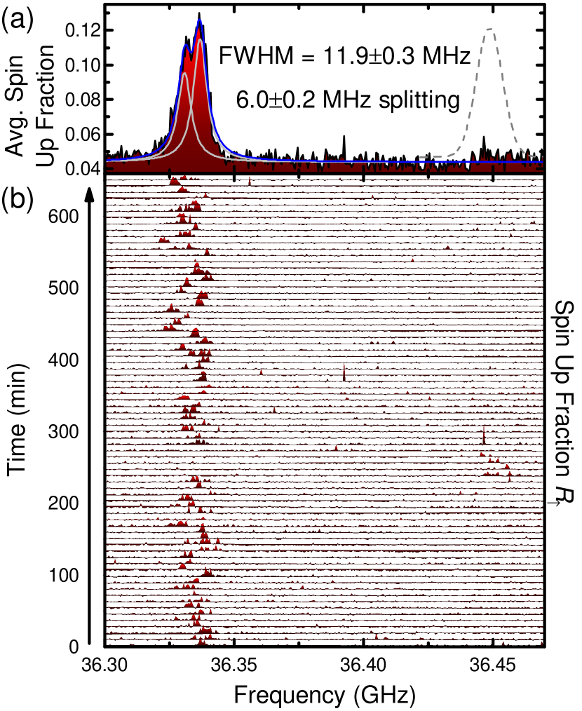
The averaged spectrum, however, is not a single resonance peak. It needs to be fitted with the sum (blue solid line) of two Gaussian peaks (gray solid lines) of equal width MHz, separated by MHz. This bimodal character suggests that the electron spin is coupled to a nearby two-level system that switches its state frequently over the timescale of the experiment. A splitting of MHz could either be caused by a hyperfine-coupled on the nearest-neighbor site Ivey and Mieher (1975), or by another donor, coupled to the donor under measurement by an exchange interaction MHz, assuming that the two-electron system is initialized in the state Kalra et al. (2013). An exchange coupling of this magnitude corresponds to an inter-donor separation of nm Wellard et al. (2003), and is compatible with the expected inter-donor distance from 20 keV molecular implantation.
The donor under study is found predominantly in the nuclear state, but other ESR spectra in the nuclear state (data not shown) allowed us to determine the value of the hyperfine coupling MHz. This value is Stark-shifted from the bulk value of MHz Feher (1959), and is very close to the hyperfine splitting reported in Pla et al. Pla et al. (2012) and computed in Mohiyaddin et al. Mohiyaddin et al. (2013).
The strong fluctuations and, therefore, the large broadening of the time-averaged ESR peak (cf. Fig. 1) make it difficult to apply a microwave pulse in exact resonance with the instantaneous ESR frequency. High-fidelity single-qubit gate operations would require a Rabi frequency much larger than , which in the present case would translate into a strong rotating magnetic field mT. Here we explore instead an easier and more reliable method based on adiabatic inversion.
The Landau-Zener theory Zener (1932) applies to the time evolution of a two-level system described by a linearly-varying time-dependent Hamiltonian, where ( corresponds to the Rabi frequency) couples the two levels. In our case the detuning between the source microwave frequency and the spin resonance is swept in time. The probability of a diabatic transition from one eigenstate to the other is given by:
| (1) |
When the rate of change of the energy difference (“sweep rate”, in frequency units) is low enough compared to the Rabi frequency , the system will adiabatically follow the instantaneous eigenstate. In the case of interest here, we consider an electron spin subject to a rotating magnetic field at frequency . Since the 31P nuclear spin remains in the state for several hours, we can treat the hyperfine field like a constant magnetic field shift, and describe the system in the Hilbert space of the electron spin alone. In the reference frame rotating at frequency , the Hamiltonian of the system reads:
| (2) |
where and are the spin Pauli matrices.
An electron spin initialized in the will be rotated to the state once the frequency sweep is complete. For fast sweep rates, the spin state cannot perfectly follow the eigenstates, resulting in an incomplete inversion, i.e. a rotation of an angle . This method has been widely applied in nuclear magnetic resonance Abragam (1961) but less often in electron spin resonance, although recent progress in high-frequency electronics is making it more appealing Doll et al. (2013).
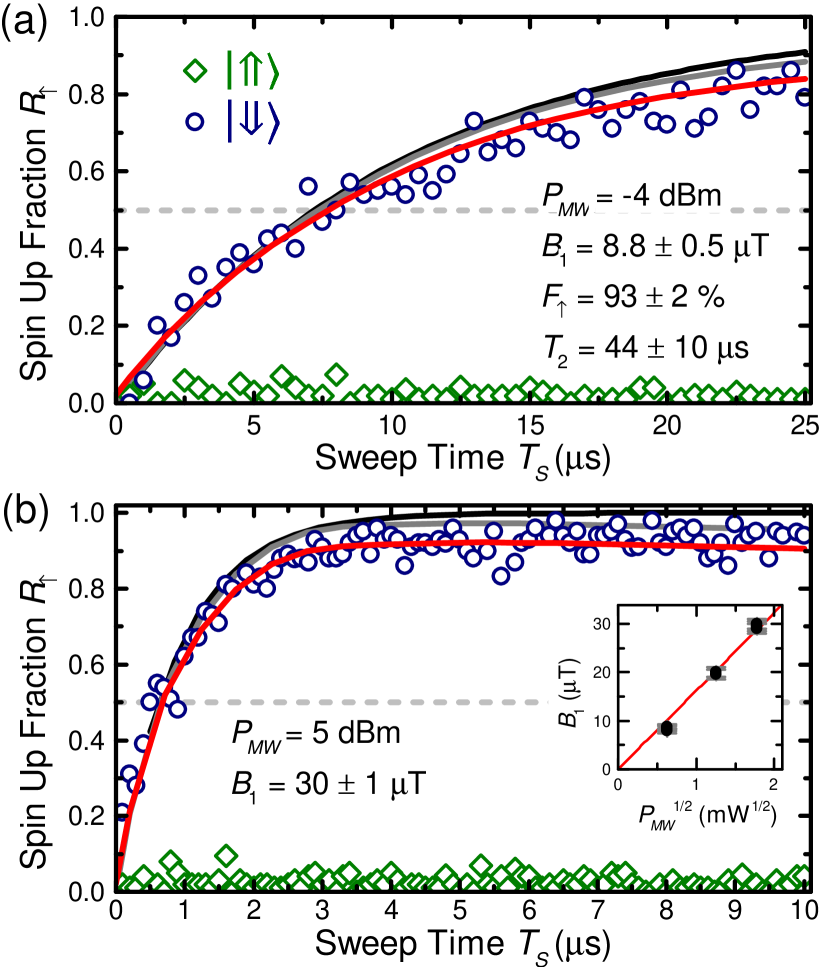
In Fig. 2 we present measurements of the electron spin-up fraction after loading an electron with spin down and performing a frequency sweep over a constant 25 MHz range, with variable sweep time . The experiment in Fig. 2(a) was conducted with a microwave power dBm at the source, while dBm was used in Fig. 2(b). For short sweep times, where is of the order of , the electron spin cannot adiabatically follow the instantaneous eigenstate. This regime can be used for controlled electron spin rotations of less than . For example, a rotation is obtained for s with dBm, and for s with dBm (dashed lines in Fig. 2). For longer sweep times and larger microwave powers [see Fig. 2(b)] the electron spin is fully inverted and the measured spin-up fraction saturates at a value close to unity, indicating high-fidelity spin inversion.
We model the experimental data using the density matrix formalism. The dephasing time of the electron spin is included in the master equation of the Lindblad form Kok and Lovett (2010)
| (3) |
where
| (4) | |||||
We then use the equation of motion (3) to numerically compute the time evolution of an electron initialized in . For a meaningful comparison to the experiment, the model also incorporates: (i) the single-shot readout fidelity for the spin-up state; (ii) the background “false counts” rate , where is the probability that the electron tunnels out of the donor during the read-out phase, in the absence of ESR excitation Pla et al. (2012). While is a fitting parameter, is obtained from a measurement of while the 31P nuclear spin is in the state (green diamonds in Fig. 2). In the present experiment, an electron temperature mK allowed us to obtain a background count rate as low as 2.2 %.
The results of our simulations are also plotted in Fig. 2. The black solid line is simply the Landau-Zener formula (1) which describes the response of an ideal system. The gray lines are density matrix simulations of the diabatic sweep, including only the time of the electron spin, while the red lines include the effect of background counts and readout fidelity. The best agreement with the experimental data is obtained by assuming a rotating magnetic field strength T ( dBm) and T ( dBm), a readout fidelity , and a decoherence time s. Modeling a total of eight datasets for three different excitation powers (only two datasets shown) allows us to verify the -dependence of , confirmed by the good agreement of the extracted values [inset of Fig. 2(b)] with a linear fit through the origin 111In contrast to the rotating field assumed in the simulations, the field in the experiment is linearly polarized. This results in the real field amplitude being a factor larger.. For all simulations, and were global parameters, i.e. the same values were used for all the simulations. The decoherence time extracted from these data is significantly shorter than that for isolated single donors in natural silicon ( s in Ref. [Pla et al., 2012]). Since exchange coupling creates an additional path for dephasing which can be very sensitive to electric field noise Hu and Das Sarma (2006), this short decoherence time further supports the possibility of having observed a weakly-coupled two-donor system, as first brought up by the bimodal shape of the ESR peak in Fig. 1(a). However, the current status of this experiment does not allow us to conclusively exclude the possibility that these effects arise from a 29Si nucleus at the nearest-neighbor site.
From the gray line in Fig. 2(b), which represents the result of the simulations without readout infidelity and background counts, we extract a maximum inversion fidelity of . This remarkable value is obtained for a moderate T and a sweep time of s. Beyond this (-dependent) optimal value of , the inversion fidelity is deteriorated by the spin decoherence. would further increase with higher values, because the inversion could then be accomplished in a time . A value of represents a dramatic improvement when compared to the inversion fidelity 222The inversion fidelity was calculated as , where is the angle control fidelity Pla et al. (2012). obtained with resonant pulses in Ref. [Pla et al., 2012], despite operating in the same 29Si nuclear spin environment.
In summary, we have presented high-fidelity adiabatic inversions of the spin of an electron bound to a donor in natural silicon. Although the nuclear spins and, possibly, a second exchange coupled 31P donor, lead to an inhomogeneous broadening of the electron resonance frequency of MHz, we are able to invert the electron spin with a fidelity of . This is made possible by the intrinsic robustness of this technique to the exact resonance frequency of the electron spin. Our result highlights the benefits of adiabatic inversion as the technique of choice for coherent control of spin qubits in environments that produce strong magnetic field fluctuations of nuclear origin, such as natural silicon and III-V semiconductors.
This research was funded by the Australian Research Council Centre of Excellence for Quantum Computation and Communication Technology (project number CE11E0096) and the US Army Research Office (W911NF-13-1-0024). We acknowledge support from the Australian National Fabrication Facility, and from the laboratory of Prof Robert Elliman at the Australian National University for the ion implantation facilities.
References
- Loss and DiVincenzo (1998) D. Loss and D. P. DiVincenzo, Phys. Rev. A 57, 120 (1998).
- Taylor et al. (2005) J. Taylor, H.-A. Engel, W. Dür, A. Yacoby, C. Marcus, P. Zoller, and M. Lukin, Nature Physics 1, 177 (2005).
- Hollenberg et al. (2006) L. Hollenberg, A. Greentree, A. Fowler, and C. Wellard, Phys. Rev. B 74, 045311 (2006).
- Koppens et al. (2006) F. H. L. Koppens, C. Buizert, K. J. Tielrooij, I. T. Vink, K. C. Nowack, T. Meunier, L. P. Kouwenhoven, and L. M. K. Vandersypen, Nature 442, 766 (2006).
- Petta et al. (2005) J. R. Petta, A. C. Johnson, J. M. Taylor, E. A. Laird, A. Yacoby, M. D. Lukin, C. M. Marcus, M. P. Hanson, and A. C. Gossard, Science 309, 2180 (2005).
- Maune et al. (2012) B. M. Maune, M. G. Borselli, B. Huang, T. D. Ladd, P. W. Deelman, K. S. Holabird, A. A. Kiselev, I. Alvarado-Rodriguez, R. S. Ross, A. E. Schmitz, M. Sokolich, C. A. Watson, M. F. Gyure, and A. T. Hunter, Nature (London) 481, 344 (2012).
- Pla et al. (2012) J. J. Pla, K. Y. Tan, J. P. Dehollain, W. H. Lim, J. J. L. Morton, D. N. Jamieson, A. S. Dzurak, and A. Morello, Nature (London) 489, 541 (2012).
- Pla et al. (2013) J. J. Pla, K. Y. Tan, J. P. Dehollain, W. H. Lim, J. J. L. Morton, F. A. Zwanenburg, D. N. Jamieson, A. S. Dzurak, and A. Morello, Nature (London) 496, 334 (2013).
- Yao, Liu, and Sham (2006) W. Yao, R.-B. Liu, and L. Sham, Physical Review B 74, 195301 (2006).
- Witzel et al. (2010) W. M. Witzel, M. S. Carroll, A. Morello, L. Cywiński, and S. Das Sarma, Phys. Rev. Lett. 105, 187602 (2010).
- Wang, Fowler, and Hollenberg (2011) D. S. Wang, A. G. Fowler, and L. C. Hollenberg, Physical Review A 83, 020302 (2011).
- Steger et al. (2012) M. Steger, K. Saeedi, M. L. W. Thewalt, J. J. L. Morton, H. Riemann, N. V. Abrosimov, P. Becker, and H.-J. Pohl, Science 336, 1280 (2012).
- Tyryshkin et al. (2012) A. M. Tyryshkin, S. Tojo, J. J. L. Morton, H. Riemann, N. V. Abrosimov, P. Becker, H.-J. Pohl, T. Schenkel, M. L. W. Thewalt, K. M. Itoh, and S. A. Lyon, Nature Materials 11, 143 (2012).
- Saeedi et al. (2013) K. Saeedi, S. Simmons, J. Z. Salvail, P. Dluhy, H. Riemann, N. V. Abrosimov, P. Becker, H.-J. Pohl, J. J. Morton, and M. L. Thewalt, Science 342, 830 (2013).
- Li et al. (2013) J.-Y. Li, C.-T. Huang, L. P. Rokhinson, and J. C. Sturm, Applied Physics Letters 103, 162105 (2013).
- Morello et al. (2010) A. Morello, J. J. Pla, F. a. Zwanenburg, K. W. Chan, K. Y. Tan, H. Huebl, M. Möttönen, C. D. Nugroho, C. Yang, J. van Donkelaar, A. D. C. Alves, D. N. Jamieson, C. C. Escott, L. C. L. Hollenberg, R. G. Clark, and A. S. Dzurak, Nature (London) 467, 687 (2010).
- Ziegler, Ziegler, and Biersack (2010) J. F. Ziegler, M. Ziegler, and J. Biersack, Nuclear Instruments and Methods in Physics Research Section B: Beam Interactions with Materials and Atoms 268, 1818 (2010).
- Dehollain et al. (2013) J. P. Dehollain, J. J. Pla, E. Siew, K. Y. Tan, A. S. Dzurak, and A. Morello, Nanotechnology 24, 015202 (2013).
- Ivey and Mieher (1975) J. L. Ivey and R. L. Mieher, Phys. Rev. B 11, 849 (1975).
- Kalra et al. (2013) R. Kalra, A. Laucht, C. Hill, and A. Morello, arXiv:1312.2197 (2013).
- Wellard et al. (2003) C. Wellard, L. Hollenberg, F. Parisoli, L. Kettle, H.-S. Goan, J. McIntosh, and D. Jamieson, Physical Review B 68, 1 (2003).
- Feher (1959) G. Feher, Phys. Rev. 114, 1219 (1959).
- Mohiyaddin et al. (2013) F. A. Mohiyaddin, R. Rahman, R. Kalra, G. Klimeck, L. C. L. Hollenberg, J. J. Pla, A. S. Dzurak, and A. Morello, Nano Letters 13, 1903 (2013).
- Zener (1932) C. Zener, Proceedings of the Royal Society of London. Series A 137, 696 (1932).
- Abragam (1961) A. Abragam, The principles of nuclear magnetism (Clarendon Press (Oxford), 1961).
- Doll et al. (2013) A. Doll, S. Pribitzer, R. Tschaggelar, and G. Jeschke, Journal of Magnetic Resonance 230, 27 (2013).
- Kok and Lovett (2010) P. Kok and B. W. Lovett, Introduction to optical quantum information processing (Cambridge University Press, 2010).
- Note (1) In contrast to the rotating field assumed in the simulations, the field in the experiment is linearly polarized. This results in the real field amplitude being a factor larger.
- Hu and Das Sarma (2006) X. Hu and S. Das Sarma, Phys. Rev. Lett. 96, 100501 (2006).
- Note (2) The inversion fidelity was calculated as , where is the angle control fidelity Pla et al. (2012).