FAST RADIAL FLOWS IN TRANSITION DISK HOLES
Abstract
Protoplanetary “transition” disks have large, mass-depleted central cavities, yet also deliver gas onto their host stars at rates comparable to disks without holes. The paradox of simultaneous transparency and accretion can be explained if gas flows inward at much higher radial speeds inside the cavity than outside the cavity, since surface density (and by extension optical depth) varies inversely with inflow velocity at fixed accretion rate. Radial speeds within the cavity might even have to approach free-fall values to explain the huge surface density contrasts inferred for transition disks. We identify observational diagnostics of fast radial inflow in channel maps made in optically thick spectral lines. Signatures include (1) twisted isophotes in maps made at low systemic velocities and (2) rotation of structures observed between maps made in high-velocity line wings. As a test case, we apply our new diagnostic tools to archival ALMA data on the transition disk HD 142527, and uncover evidence for free-fall radial velocities inside its cavity. Although the observed kinematics are also consistent with a disk warp, the radial inflow scenario is preferred because it predicts low surface densities that appear consistent with recent observations of optically thin CO isotopologues in this disk. How material in the disk cavity sheds its angular momentum wholesale to fall freely onto the star is an unsolved problem; gravitational torques exerted by giant planets or brown dwarfs are briefly discussed as a candidate mechanism.
1 INTRODUCTION
A subset of T Tauri and Herbig Ae disks have large, mass-depleted cavities in their inner regions, as inferred from their infrared spectra (e.g., Kim et al., 2013) or spatially resolved imaging at infrared (e.g., Geers et al., 2007) and mm wavelengths (e.g., Brown et al., 2009). The cavities in these “transition” disks have radii ranging from 4 AU (TW Hya; Calvet et al., 2002; Hughes et al., 2007) to 20 AU (GM Aur; Hughes et al., 2009) to 40–50 AU (LkCa 15; Andrews et al., 2011; Isella et al., 2012) to 130–140 AU (HD 142527; Casassus et al., 2013). The suspicion is that dynamical interactions with nascent planetary systems evacuate the inner disk regions (e.g., Zhu et al., 2011).
Surprisingly, despite their optically thin cavities, many transition disks appear to be accreting gas at fairly normal rates. Stellar accretion rates in transition disks range from (TW Hya; Muzerolle et al., 2000) to (GM Aur; Gullbring et al., 1998; Calvet et al., 2005) to (HD 142527; Garcia Lopez et al., 2006). These rates overlap with those for conventional disks without cavities, although the median for transitional disks may be a factor of 10 lower than for conventional disks (Najita et al., 2007; Espaillat et al., 2012; Kim et al., 2013).111Of course, there are disks, transitional and otherwise, with lower accretion rates than those cited in the main text (e.g., Sicilia-Aguilar et al. 2010; Rigliaco et al. 2012)—at least insofar as attempts to measure accretion rates can be trusted (e.g., De Marchi et al. 2010; Curran et al. 2011; Alcalá et al. 2013). Some transitional disks with unmeasurably low stellar accretion rates may harbor stellar binaries whose torques are strong enough to stave off accretion (e.g., CoKu Tau/4; Ireland & Kraus 2008; Najita et al. 2007). Our focus in this paper is on healthily accreting transitional disks, as they pose the greatest paradox: how can they have cavities and accrete at the same time?
It is sometimes thought that transition disk cavities are created by planets consuming material from the outer disk and thereby starving the inner disk. This is unlikely to be correct — or at least it cannot be the whole story — because a starved inner disk would also starve the host star, contrary to the observed values of cited above. Modeling of disk spectra and images reveals that surface density contrasts inside and outside cavities can be (e.g., Calvet et al., 2005). Planets inside the cavity cannot simultaneously eat % of the mass flowing inward from the outer disk and still leave enough for their host star to accrete at near-normal rates. If we interpret the factor-of-10 lower for transition disks as arising from planets consuming 90% of the accretion flow from the outer disk and leaving the remaining 10% for the central star (e.g., Lubow & D’Angelo, 2006), then the surface density just inside the planet’s orbit would decrease by only a factor of 10, which is almost certainly too small to render the inner disk optically thin — all other factors being equal.
In this paper, we describe a way for transition disks to have their cake (possess optically thin cavities) and eat it too (accrete at normal rates). The dilemma can be resolved by (somehow) increasing the radial accretion velocity inside the cavity, thereby concomitantly lowering the surface densities there. For a given radius and steady disk accretion rate , we have . Just outside the cavity, is large because accretion in the outer disk is diffusive (“viscous”) and slow (, where is the disk vertical thickness, is the Shakura-Sunyaev stress parameter, and is the Keplerian orbital velocity). Just inside the cavity, the accretion velocity is somehow boosted — could, in principle, approach its maximum of — so that is lowered, conceivably by orders of magnitude, while maintaining the same mass flow rate as in the outer disk.
Gravitational (as opposed to magnetic or hydrodynamic) torques are an obvious candidate for catastrophically removing angular momentum from gas inside the cavity. In galaxies, gravitational torques are exerted by stars that arrange themselves into non-axisymmetric patterns. A stellar bar (a perturbation with azimuthal wavenumber ) eviscerates the interior of the 3-kpc molecular ring at the center of our Galaxy (Schwarz, 1981; Binney et al., 1991); an eccentric stellar disk () may be funneling gas onto the star-forming nucleus of M31 (Chang et al., 2007); and a complex nest of and stellar potentials force-feeds gas onto quasars (Shlosman et al., 1989; Hopkins & Quataert, 2011). In these galaxy-scale examples, radial inflow velocities can approach free-fall rates.
The role of stars in galaxies might be played by planets in transition disks. We like this interpretation, but it is not without difficulty. The cavities are so large (they are not annular gaps) and so clean that appeals are made to rather extreme parameters. As many as four planets, each weighing up to 10 , have been posited to carve out a given cavity (Zhu et al., 2011; Dodson-Robinson & Salyk, 2011).222Even multiple super-Jovian planets are reportedly not enough: grain growth and dust filtration at the cavity rim are invoked in addition to planets to make the cavity sufficiently transparent (Zhu et al., 2011; Dong et al., 2012). At least in the case of the transition disk around LkCa 15, there might be one (but so far only one) actively accreting super-Jovian planet located well inside the disk cavity (Kraus & Ireland, 2012). Some assistance in driving the accretion flow inside the cavity may be obtained from the gravitational potential of the outer disk itself, if that disk is sufficiently clumpy and massive (for examples of clumpy disks, see the observations of IRS 48 by van der Marel et al. 2013, and the studies of HD 142527 by Casassus et al. 2013 and Fukagawa et al. 2013). Just inside a non-axisymmetric outer disk, gas streamlines can cross, shock, and plunge inward (e.g., Paczynski, 1977).
Disk radial velocities driven by embedded massive planets or brown dwarfs can be healthy fractions of orbital (azimuthal) velocities. We derive a crude estimate333Our “zero-dimensional” analysis ignores the fact that actual disk flows around planets are two-dimensional and dominated by non-axisymmetric streams flowing in and around planetary Hill spheres. Still, some indirect empirical support for the scalings in equation (1) has been found by Fung et al. (2013). for by equating the one-sided Lindblad torque — the amount of angular momentum transmitted outward across a planet’s orbit (Goldreich & Tremaine, 1980) — with the angular momentum advected inward by accretion, . This balance yields
| (1) |
where we have used the total linear Lindblad torque, integrated over all resonances outside the torque cut-off zone at distances away from the planet (see, e.g., Goodman & Rafikov 2001 or Crida et al. 2006, and references therein). For a planet mass , a host stellar mass , and a typical disk aspect ratio , equation (1) evaluates to
| (2) |
Modern heterodyne receivers on (sub)millimeter wavelength interferometers routinely observe disks at 0.1 km s-1 resolution, and the Atacama Large Millimeter Array (ALMA) is expected to provide high sensitivity data at finer velocity scales yet. Evidence for free-fall radial velocities can be found in the HCO+ filament within the disk cavity around HD 142527. Casassus et al. (2013) discovered this filament to be oriented nearly radially; in estimating for this system, they assumed (although the velocities of the HCO+ filament were not actually quoted in their study).
Regardless of what is actually accelerating the accretion, we ask here whether we can test observationally the idea that transition disk cavities have fast (nearly free-fall) radial flows. We present in §2 some predicted observational signatures of radial inflow in spectrally and spatially resolved (sub)millimeter-wavelength maps of molecular emission lines. A sample case study based on the HD 142527 disk is presented in §3. We conclude in §4.
2 OBSERVATIONAL SIGNATURES OF RADIAL INFLOW
Interferometers observing the (sub)millimeter and radio spectral line transitions of molecular gas tracers produce a spatially resolved map of the source for each frequency (velocity) channel. A disk in Keplerian rotation has well-ordered gas velocities, and so line emission in a particular channel “highlights” disk material that is appropriately Doppler shifted (e.g., Omodaka et al., 1992; Beckwith & Sargent, 1993). Adding a fast radial inflow to the normal Keplerian velocity field alters the morphology of channel map emission (cf. Tang et al., 2012). We identify two related observational signatures of radial inflow in a disk cavity: (1) twisted isophotes in the channel map corresponding to the systemic velocity (§2.1), and (2) rotation of features seen between maps made in high-velocity wings (§2.2). While distinctive, neither of these features is entirely unique, and must be disentangled from other non-Keplerian effects (§2.3).
Our analysis uses two axisymmetric models: a razor-thin disk and a three-dimensional (3D) disk. The razor-thin model is a pedagogical tool to develop intuition. The 3D model is more realistic and presents a platform to test the razor-thin model as well as analyze mock data products.
Both models treat the gas velocities within the cavity () as having an inward radial component that is some constant fraction of the local circular Keplerian velocity. The velocity field is then
| (3) | ||||
| (4) |
both for the razor-thin model and the 3D model. Here is the azimuthal angle in the disk plane, and variations in bulk velocity with height are ignored (but see §2.3). Outside the cavity, gas is assumed to follow circular Keplerian orbits. Our assumption that the radial inflow is axisymmetric is probably unrealistic — certainly so if the inflow is driven by large-scale gravitational torques as we have described in §1. Nevertheless we assume axisymmetry to gain a foothold on the problem.
The disk is inclined by a viewing angle about the axis, where corresponds to a disk seen face-on. Note that the effects we will discuss are sensitive to the spin orientation of the disk, and so can range between and without degeneracy. Inclinations imply that the line-of-sight component of the orbital angular momentum points toward the observer, whereas implies that the line-of-sight component points away.
For the razor-thin model, the projected line-of-sight velocity is444We can set equal to either or . The degeneracy arises because we can choose the disk’s ascending ( toward the observer) node on the sky plane to coincide with either the axis (our convention in this paper) or the axis. Another way to say this is that is degenerate with .
| (5) |
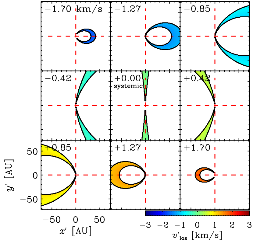
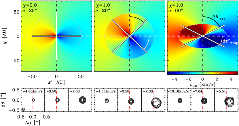
We utilize primed coordinates to denote values measured by the observer; the spatial coordinates in the sky plane are and . The azimuth measured in the disk plane is related to the on-sky angle by . The left panel of Figure 1 shows the morphology of line emission for a razor-thin disk with no inflow.
We compute an analogous 3D disk model that simulates the 12CO =32 line emission from a disk with a total gas mass of 0.01 , a spatially constant CO:H2 number-abundance fraction of , and a Gaussian vertical density distribution ( with a scale height of ). The surface density profile is that of a thin, viscously accreting disk (Lynden-Bell & Pringle, 1974): with scale radius AU and an outer truncation radius of 300 AU. Since our focus in this paper is on the velocity field and not on the density structure, we have not included any reduction of within the cavity. This simplification should not introduce serious error as long as the cavity region remains optically thick in 12CO emission—we estimate that this condition holds for yr and AU, even if jumps discontinuously from 0 to 1 across the cavity boundary. These requirements are satisfied for HD 142527, our subject test case of §3.
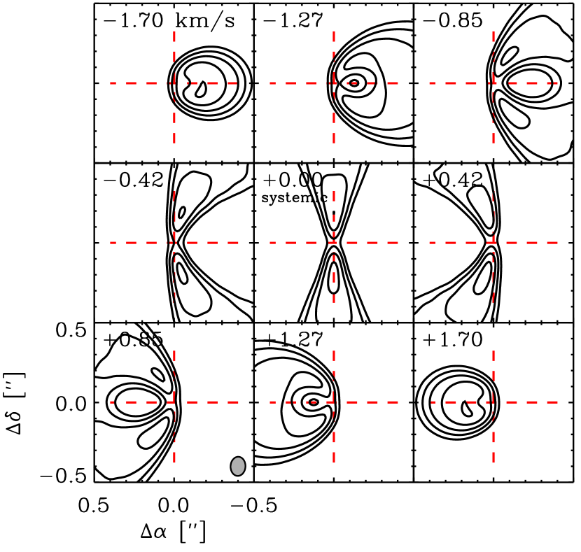
The model is vertically isothermal with a power-law radial temperature profile, AU K: this temperature profile is used only to calculate the level populations of molecules, not the hydrostatic disk structure. The mass of the central star is 1 , the distance to the observer is 145 pc, and the cavity radius is AU. The disk inclination and radial inflow parameter are variable. We use the modeling capabilities of LIME (Brinch & Hogerheijde, 2010) to simulate high-resolution channel maps assuming LTE conditions and a turbulent linewidth of km s-1. We then use CASA to sample and deconvolve the Hanning-smoothed visibilities with a spectral resolution of 0.212 km s-1 and a spatial resolution of 01: these parameters should typify spectral line observations of disks by ALMA when the instrument reaches technical maturity. The right panel of Figure 1 shows the channel maps from a 3D disk model (), zoomed into the inner 05. Comparing the left and right panels of Figure 1 reveals how the velocity field of the razor-thin model offers a guide to the morphology of line emission in the channel maps of the 3D model (see also Beckwith & Sargent, 1993).
2.1 Twisted Isophotes at the Systemic Velocity
The gas with no bulk motion relative to the systemic velocity of the disk has . From equation (5), this gas satisfies
| (6) |
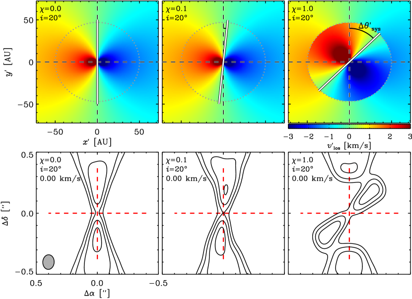
which implies that in the disk plane, and on the sky. For (no radial inflow), : the systemic velocity channel probes gas that lies along the minor axis of the disk as seen in projection (see Figure 1, central panels). When , the isovelocity contours at will be rotated by an angle . This rotation is evident in the top set of panels in Figure 2, which show the line-of-sight velocity fields of a razor-thin disk for various values of inside the disk cavity. The rotation can also be seen in the isophotes observed at the systemic velocity of the corresponding 3D model; the bottom panels of Figure 2 show that the isophotes in the channel maps “twist” at .
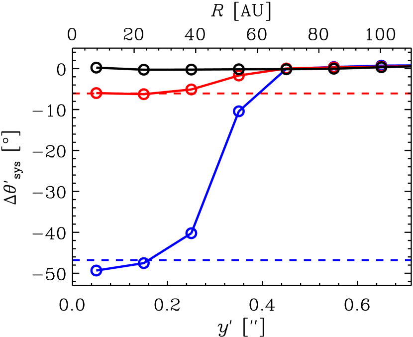
The isophote twist in the systemic velocity channel map can be measured as a function of radius. We perform this measurement by first dividing the 3D disk model into concentric annuli, and further splitting each annulus into its top () and bottom () halves. For each half-annulus, an intensity-weighted centroid (i.e., a “center of brightness”) is computed. The rotation angle is then evaluated from the line joining the centroid positions of the top and bottom halves of a given annulus at radius . The left panel of Figure 3 shows for three values of . Note how is accurately predicted by the razor-thin model, at least for the example inclination angle . In the mock observations of the 3D model, the transition between and , occurring near the cavity radius ( AU), is smeared by the 01 beam. How well we can measure in practice depends on the ratio of the beam size, , to the peak signal-to-noise, (Reid et al., 1988). We estimate that a robust measurement of the twist requires . For the 01 beam size adopted in Figure 3, this requirement is met with for , or with any detection of the line for . Any measurement of an isophote twist from a synthesized image should be accompanied by a model imaged using the same sampling as the data, since the position angle of the resolution element can significantly alter the appearance of the image (Guilloteau & Dutrey, 1998).
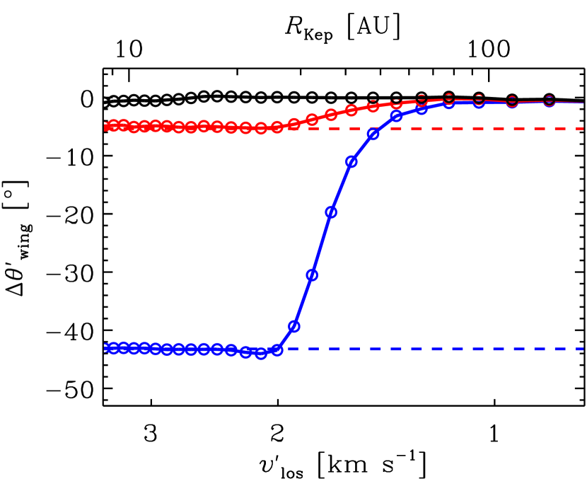
2.2 Maximum LOS Velocities: Wing Rotation
We now consider gas moving at the highest line-of-sight velocities, responsible for emission in the spectral line wings. Maximizing equation (5) with respect to yields
| (7) |
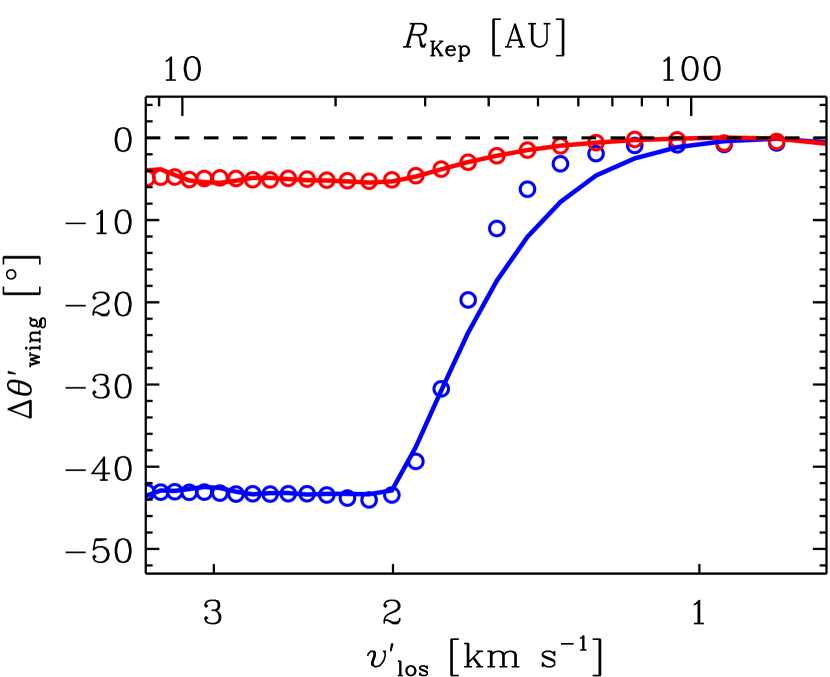
or in the disk plane and on the sky. Radial inflow causes the maximum isovelocity contour to rotate away from the disk major axis by . Figure 4 shows the velocity fields for three razor-thin disk models, together with simulated channel maps for the corresponding 3D models. Where there is inflow, emission from the 3D model is systematically rotated away from the disk major axis. For extreme values of , line-of-sight velocities within the cavity are noticeably greater than for the case with no inflow (see top panels of Figure 4). Correspondingly, emission from the line wings is brighter — compare channels of the same velocity between the and models at fixed (bottom panels of Figure 4) — although it should be remembered that any decrease in the surface density inside the cavity (not modeled here) may reduce the intensity enhancement. The last panel of Figure 4 demonstrates that . This difference is further quantified in Figure 5, which shows that increases with increasing and . Note how is reduced for highly inclined disks, just opposite to the behavior of . Therefore, measuring is easier at low inclinations, while measuring is easier at high inclinations. Clearly, disk orientation is a consideration when designing observations to detect either rotational signature.
To measure for the 3D disk model, we employ a procedure similar to the one we devised for . For each spectral channel, we measure the position of the intensity-weighted centroid (fitting two-dimensional Gaussians produces consistent results). Pairs of these positions are constructed from channels blue- and red-shifted by the same velocity relative to the systemic channel. For a given velocity pair, the angle is calculated from the line segment joining the two centroid positions. The second panel in Figure 3 shows as a function of channel velocity for a few values of . Rotation is evident for all channel velocities equal to the Kepler velocities of material within the cavity. As was the case for , the maximum value of measured in the 3D model is accurately predicted by the razor-thin model. Measuring in practice requires . For the model disks shown in Figure 4 with , this beam size requirement is met when and with relatively large beam sizes, 05 or 07 for or 60°, respectively.
In principle, the inclination and inflow parameter can be calculated if both and are measured. In this case the product and the ratio . The disk inclination so derived could then be compared to independent measurements.
These observational signatures of radial inflow — twisted isophotes () and wing rotation () — are intrinsically kinematic features, and therefore should be present regardless of which spectral line is used as a tracer of the projected disk velocity field. That said, there is an obvious advantage to using lines with higher optical depths (e.g., 12CO, HCO+), since they are more likely to be bright enough inside the low-density cavities of transitional disks (e.g., Bruderer, 2013) to enable robust measurements of radial inflow.
2.3 Disentangling Radial Inflow from Other Non-Keplerian Effects
The rotational signatures of inflow identified in §2.1 and §2.2 can be mimicked to varying degrees by other phenomena. We discuss four possible “contaminants” and how one might disambiguate between these different scenarios.
2.3.1 Radial outflow
Molecular gas can be entrained in winds flowing up and radially outward from the disk surface (e.g., Pontoppidan et al., 2011; Bast et al., 2011; Klaassen et al., 2013). Radial outflow would cause the systemic velocity isophotes and the wing emission to rotate in the direction opposite to that for radial inflow. Distinguishing inflow from outflow requires that we resolve the spin orientation of the disk; i.e., we need to decide whether or . The way to break this degeneracy is to use spatially resolved channel maps to decide which limb is approaching and which limb is receding, and then to combine this information with some asymmetry along the projected minor axis. The asymmetry could be manifested in the orientation of a polar jet pointed toward the observer (i.e., whether the jet points along the positive or negative minor axis). Alternatively, one could observe, at any wavelength, a spectral line (Dutrey et al., 1998; Guilloteau & Dutrey, 1998; Rosenfeld et al., 2013) or continuum (Augereau et al., 1999; Weinberger et al., 1999; Fukagawa et al., 2006; Thalmann et al., 2010) brightness asymmetry arising from the disk’s orientation. Of course it is also possible that one molecular line traces an outflowing disk wind, say because it probes gas at high altitude above the midplane, while another traces radial inflow, closer to the midplane.
2.3.2 Infall from a molecular envelope
Gas from the parent molecular cloud may continue to accrete onto the protoplanetary disk at early times (Stahler et al., 1994; Yorke & Bodenheimer, 1999; Brinch et al., 2007). Differential rotation and accelerating infall will mimic the spatio-kinematic signatures of inflow (cf. Brinch et al., 2008; Tang et al., 2012). However, the spatial scale of an infalling envelope should be comparable to or larger than the disk itself, and should not be confined to a central cavity. Furthermore, for an isolated source, the duration of infall should be considerably shorter than the lifetime of the disk (e.g., Piétu et al., 2005). Evidence for local cloud material might be indicated by high extinction values, very red infrared spectral energy distributions, or contamination (self-absorption and/or emission on much larger angular scales) in single dish molecular line spectra. Most of the currently known transition disks do not exhibit any clear evidence for a remnant envelope structure.
2.3.3 Vertical disk structure
Line emission from optically thick gas typically originates in disk surface layers located at large vertical heights above the midplane (e.g., van Zadelhoff et al., 2001; Dartois et al., 2003; Pavlyuchenkov et al., 2007; Semenov et al., 2008). Therefore, in channel maps, the blue- and red-shifted emission structures are not generally collinear with the stellar position; rather, they appear rotated away from the midplane in opposite directions from one another (Rosenfeld et al., 2013; de Gregorio-Monsalvo et al., 2013). These rotations of the blue- and red-shifted line wings would effectively cancel out in the procedure we developed in §2.2 to measure . Moreover, vertical structure does not twist the isophotes at the systemic velocity (i.e., ). In sum, vertical structure should pose little danger of confusion in efforts to characterize radial inflow.
2.3.4 A warp
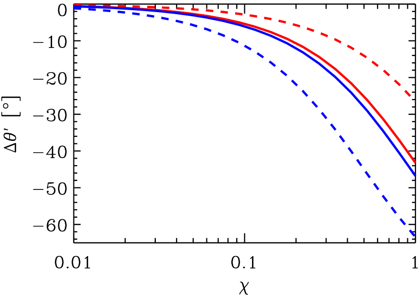
A warp — introduced, for example, by a perturbing body whose orbit is inclined to the disk plane (Larwood, 1997; Marzari & Nelson, 2009) — also changes the morphology of line emission in channel maps. We have found that, unfortunately, the warp-induced changes in the channel maps are practically identical to those induced by a radial inflow. 555We also tested whether disk eccentricity was degenerate with the signature of radial inflow, and found that it was not (data not shown). At its most basic, a warp comprises an inner disk that is misaligned with an outer disk, and is described by three parameters: the radius where the inner disk transitions to the outer disk, the inclination of the inner disk relative to the sky plane, and the orientation of the inner disk, i.e., the longitude of ascending ( toward the observer) node, measured in the sky plane and referred to the axis (as a reminder, the outer disk has inclination relative to the sky plane and orientation ). An equivalent description uses the outer disk as the reference plane; under this alternate convention, the inner disk inclination relative to the outer disk is , and its longitude of ascending node is , measured in the outer disk plane and referred to the axis. The angles in the two reference systems are related by
| (8) | ||||
| (9) |
Figure 6 shows and for two 3D disk models with warps (solid curves) overlaid on our previous results for disk models with radial inflow (open circles). The similarity between these rotation angle patterns demonstrates that a warp with the right parameters (see caption) can masquerade as inflow in channel maps. Furthermore, increasing can brighten wing emission in the same way that increasing does (data not shown; see §2.2; Rosenfeld et al., 2012).
Distinguishing inflow from a warp requires additional data and modeling. A warped disk located in a region that is known to be optically thin at continuum wavelengths would need to have its opacity be reduced by large factors by, e.g., grain growth or dust filtration at the cavity rim. By contrast, in the fast inflow model, the opacity need not change much, if at all, since the surface density reduction that accompanies fast inflow would account for most if not all of the cavity’s transparency. Spatially resolved, multi-wavelength imaging of the disk cavity can serve to constrain changes in the dust size distribution. And one can utilize emission lines from rarer, optically thin gas species (e.g., Bruderer 2013) to measure total gas surface densities. In §3 we wrestle again with the warp/inflow degeneracy using real observations.666A warp and inflow are not mutually exclusive possibilities — the two phenomena might be driven simultaneously by companions inside the disk cavity.
3 A CASE STUDY: HD 142527
We consider the remarkable transition disk hosted by the young F star HD 142527. At a distance of pc (Verhoeff et al., 2011), the disk has a large dust-depleted cavity of radius AU that has been imaged in near-infrared scattered light (Fukagawa et al., 2006; Casassus et al., 2012; Rameau et al., 2012; Canovas et al., 2013) and mid-infrared thermal emission (Fujiwara et al., 2006; Verhoeff et al., 2011). The cavity is not completely devoid of dust; Verhoeff et al. (2011) required an optically thick disk (and even an optically thin halo) interior to 30 AU to explain the observed near-infrared and mid-infrared emission. ALMA Band 7 (345 GHz) observations presented by Casassus et al. (2013) resolved the highly asymmetric dust ring at that was originally noted by Ohashi (2008). The ALMA data clearly demonstrate that molecular gas resides inside the cavity, emitting in the 12CO =32 and HCO+ =43 lines. We have already noted the nearly free-fall radial velocities implied by the HCO+ filament (§1).
We apply the tools developed in §2 to the archival ALMA data on CO and HCO+ line emission. We aim here only for a first look at the kinematics, and so forego an extensive modeling effort, fixing in advance the disk mass (), scale radius ( AU), disk temperature ( K), and outer truncation radius (300 AU). We also adopt literature values for the stellar mass (; Casassus et al., 2013) and viewing geometry for the outer disk (, with the projected major axis oriented at position angle PA = -20;777Alternatively, if our -axis points west and our -axis points north, then . Fujiwara et al., 2006; Verhoeff et al., 2011). The inclination and PA of the outer disk are based on CO channel maps together with thermal mid-infrared images which show that the eastern side of the disk appears brighter than the western side; on the eastern side we are seeing the portion of the cavity rim located farther from the observer and directly illuminated by starlight. The line-of-sight velocities reported below are all relative to systemic; the systemic velocity is +3.64 km s-1 relative to the local standard of rest, as we deduced from visual inspection of the CO channel maps.
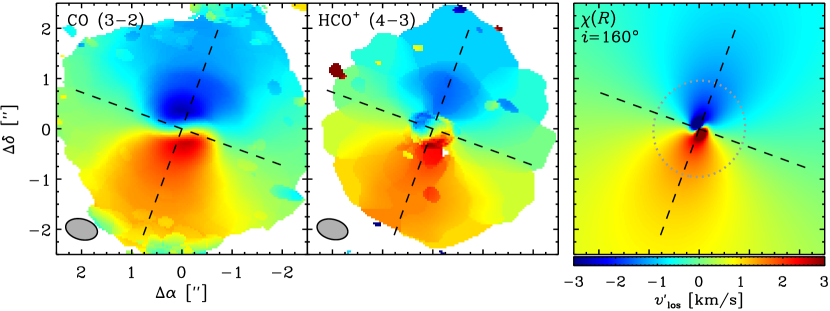
Figure 7 shows the first moment maps for the CO and HCO+ emission lines. The first moment or intensity-weighted line-of-sight velocity appears twisted near the disk center (). With respect to the orientation defined by the outer disk, the twist in the inner disk is counter-clockwise, which given implies radial inflow. Furthermore, the twist is of order 1 radian in magnitude, which implies a radial speed comparable to Keplerian (). Compare the first moment maps (left and center panels) with the velocity field of a model razor-thin disk with a fast inflow (right panel; cf. Figure 4), and recognize that the comparison is only meant to be suggestive since the velocity field is not the same as the intensity-weighted velocity.
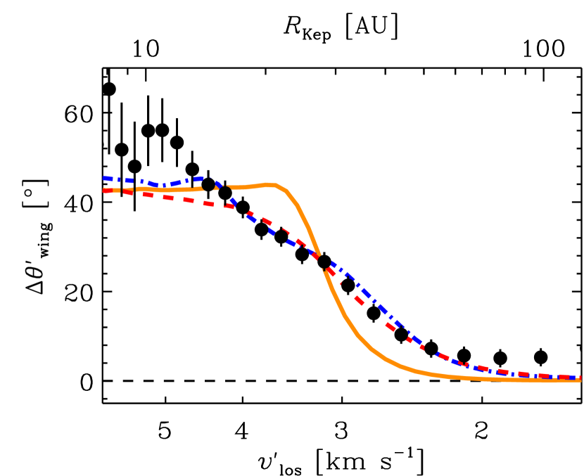
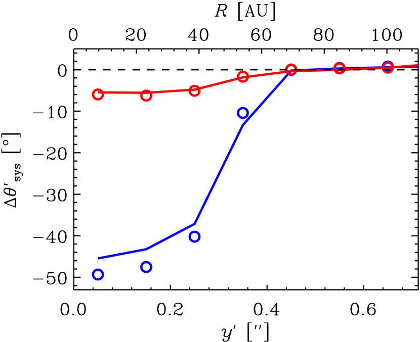
Figure 8 compares the measured in the CO line with predictions from several models. A constant model does not fit the data as well as a variable AU model that introduces the twist incrementally. The variable model does as well as a warped disk model (cf. §2.3.4) in which the warp is likewise introduced gradually. To mock up a warp induced by a planet as described by linear secular theory (e.g., Dawson et al., 2011), we ramp up the relative inclination linearly from 0 to its final value , and ramp down the nodal angle linearly from to , as the disk radius decreases from to AU.
At the highest velocities/smallest radii probed in Figure 8, all our models systematically underpredict . For the inflow model, the fit at small radii could be improved by having the azimuthal velocity decrease by a few tens of percent in tandem with the increase in radial inflow velocity. The large synthesized beam size (064041, PA = 75.5∘) precludes us from constructing a plot of showing what would presumably be large twists at small radii (cf. Figure 3, which was made assuming a beam size of 01).
At the smallest velocities/largest radii, there appears in Figure 8 to be a constant offset in of about 6 degrees. The offset may be due to a systematic error in the position angle we assumed for the outer disk. Another source of error at these low velocities may be in our systemic velocity (see Hughes et al. 2011 for a method to quantify this uncertainty).
To summarize, our first-cut analysis of the Casassus et al. (2013) ALMA observations of the HD 142527 disk demonstrates that the predicted spatio-kinematic signatures of fast radial inflow are eminently detectable, and merits a dedicated pursuit of inflow in a general sample of transition disks. Additional observations and modeling are posited to distinguish between a fast inflow or warp origin for the observed kinematics. This particular disk is especially challenging to interpret because of its complex and non-axisymmetric structures (Fukagawa et al., 2006; Fujiwara et al., 2006; Verhoeff et al., 2011; Casassus et al., 2012; Honda et al., 2012; Rameau et al., 2012; Casassus et al., 2013; Canovas et al., 2013). The disk interior to AU that was inferred by Verhoeff et al. (2011) could, in principle, support a warp. Observations of an optically thin line that resolve the central cavity would help clarify the situation, to confirm the lower gas surface densities that should accompany fast inflow. Indeed, a recent study of the 13CO and C18O =32 lines in this disk by Fukagawa et al. (2013) support the inflow scenario: they detect little (if any) emission from these optically thin isotopologues inside the disk cavity. No evidence for twisted isophotes or wing rotation is noted by Fukagawa et al. (2013) in these lines, but that is not surprising, as the emission is too faint — the current S/N is too low — inside the cavity region to detect these features.
4 CONCLUSIONS
Radial inflow of gas at velocities approaching free fall can account for both the depleted densities inside transition disk cavities and the relatively normal stellar accretion rates they maintain. We have demonstrated that high spatial and spectral resolution observations of molecular emission lines with (sub)millimeter wavelength interferometers — particularly ALMA — can detect inflow by virtue of its two key signatures: twisted isophotes at the systemic velocity, and rotated emission patterns in channel maps made in the line wings. We developed quantitative diagnostics of channel maps to characterize radial inflow, and discussed various real-world complications. Of these, the most serious is a warp.
We tested our inflow diagnostics on archival ALMA observations of the HD 142527 transition disk, uncovering a booming signal consistent with free-fall inflow velocities at distances of 25–50 AU from the host star. Nevertheless a warped disk at these radii can also reproduce the large, order-unity rotations seen in the CO and HCO+ line wings. Whether the HD 142527 disk cavity contains a fast radial inflow or a warped disk (or both), the only mechanism on the table now that can explain either phenomenon involves strong gravitational torques, exerted by one or more giant planets/brown dwarfs/low-mass stars (as yet undetected; see Biller et al., 2012; Casassus et al., 2013). Fast flows should also produce strong shocks in disks. We have not investigated the signatures of such shocks; the observables depend on details such as the density and the cooling mechanisms of shocked material. In the central cavity of the circumbinary disk around GG Tau A, Beck et al. (2012) have detected hot H2 that may trace shocks internal to the accretion flow.
References
- Alcalá et al. (2013) Alcalá, J. M., Natta, A., Manara, C. F., Spezzi, L., Stelzer, B., Frasca, A., Biazzo, K., Covino, E., Randich, S., Rigliaco, E., Testi, L., Comerón, F., Cupani, G., & D’Elia, V. 2013, ArXiv e-prints
- Andrews et al. (2011) Andrews, S. M., Rosenfeld, K. A., Wilner, D. J., & Bremer, M. 2011, ApJ, 742, L5
- Augereau et al. (1999) Augereau, J. C., Lagrange, A. M., Mouillet, D., Papaloizou, J. C. B., & Grorod, P. A. 1999, A&A, 348, 557
- Bast et al. (2011) Bast, J. E., Brown, J. M., Herczeg, G. J., van Dishoeck, E. F., & Pontoppidan, K. M. 2011, A&A, 527, A119
- Beck et al. (2012) Beck, T. L., Bary, J. S., Dutrey, A., Piétu, V., Guilloteau, S., Lubow, S. H., & Simon, M. 2012, ApJ, 754, 72
- Beckwith & Sargent (1993) Beckwith, S. V. W. & Sargent, A. I. 1993, ApJ, 402, 280
- Biller et al. (2012) Biller, B., Lacour, S., Juhász, A., Benisty, M., Chauvin, G., Olofsson, J., Pott, J.-U., Müller, A., Sicilia-Aguilar, A., Bonnefoy, M., Tuthill, P., Thebault, P., Henning, T., & Crida, A. 2012, ApJ, 753, L38
- Binney et al. (1991) Binney, J., Gerhard, O. E., Stark, A. A., Bally, J., & Uchida, K. I. 1991, MNRAS, 252, 210
- Brinch et al. (2007) Brinch, C., Crapsi, A., Jørgensen, J. K., Hogerheijde, M. R., & Hill, T. 2007, A&A, 475, 915
- Brinch & Hogerheijde (2010) Brinch, C. & Hogerheijde, M. R. 2010, A&A, 523, A25
- Brinch et al. (2008) Brinch, C., Hogerheijde, M. R., & Richling, S. 2008, A&A, 489, 607
- Brown et al. (2009) Brown, J. M., Blake, G. A., Qi, C., Dullemond, C. P., Wilner, D. J., & Williams, J. P. 2009, ApJ, 704, 496
- Bruderer (2013) Bruderer, S. 2013, ArXiv e-prints
- Calvet et al. (2002) Calvet, N., D’Alessio, P., Hartmann, L., Wilner, D., Walsh, A., & Sitko, M. 2002, ApJ, 568, 1008
- Calvet et al. (2005) Calvet, N., D’Alessio, P., Watson, D. M., Franco-Hernández, R., Furlan, E., Green, J., Sutter, P. M., Forrest, W. J., Hartmann, L., Uchida, K. I., Keller, L. D., Sargent, B., Najita, J., Herter, T. L., Barry, D. J., & Hall, P. 2005, ApJ, 630, L185
- Canovas et al. (2013) Canovas, H., Ménard, F., Hales, A., Jordán, A., Schreiber, M. R., Casassus, S., Gledhill, T. M., & Pinte, C. 2013, A&A, 556, A123
- Casassus et al. (2012) Casassus, S., Perez M., S., Jordán, A., Ménard, F., Cuadra, J., Schreiber, M. R., Hales, A. S., & Ercolano, B. 2012, ApJ, 754, L31
- Casassus et al. (2013) Casassus, S., van der Plas, G., M, S. P., Dent, W. R. F., Fomalont, E., Hagelberg, J., Hales, A., Jordán, A., Mawet, D., Ménard, F., Wootten, A., Wilner, D., Hughes, A. M., Schreiber, M. R., Girard, J. H., Ercolano, B., Canovas, H., Román, P. E., & Salinas, V. 2013, Nature, 493, 191
- Chang et al. (2007) Chang, P., Murray-Clay, R., Chiang, E., & Quataert, E. 2007, ApJ, 668, 236
- Crida et al. (2006) Crida, A., Morbidelli, A., & Masset, F. 2006, Icarus, 181, 587
- Curran et al. (2011) Curran, R. L., Argiroffi, C., Sacco, G. G., Orlando, S., Peres, G., Reale, F., & Maggio, A. 2011, A&A, 526, A104
- Dartois et al. (2003) Dartois, E., Dutrey, A., & Guilloteau, S. 2003, A&A, 399, 773
- Dawson et al. (2011) Dawson, R. I., Murray-Clay, R. A., & Fabrycky, D. C. 2011, ApJ, 743, L17
- de Gregorio-Monsalvo et al. (2013) de Gregorio-Monsalvo, I., Ménard, F., Dent, W., Pinte, C., López, C., Klaassen, P., Hales, A., Cortés, P., Rawlings, M. G., Tachihara, K., Testi, L., Takahashi, S., Chapillon, E., Mathews, G., Juhasz, A., Akiyama, E., Higuchi, A. E., Saito, M., Nyman, L.-Å., Phillips, N., Rodń, J., Corder, S., & Van Kempen, T. 2013, ArXiv e-prints
- De Marchi et al. (2010) De Marchi, G., Panagia, N., & Romaniello, M. 2010, ApJ, 715, 1
- Dodson-Robinson & Salyk (2011) Dodson-Robinson, S. E. & Salyk, C. 2011, ApJ, 738, 131
- Dong et al. (2012) Dong, R., Hashimoto, J., Rafikov, R., Zhu, Z., Whitney, B., Kudo, T., Muto, T., Brandt, T., McClure, M. K., Wisniewski, J., Abe, L., Brandner, W., Carson, J., Egner, S., Feldt, M., Goto, M., Grady, C., Guyon, O., Hayano, Y., Hayashi, M., Hayashi, S., Henning, T., Hodapp, K. W., Ishii, M., Iye, M., Janson, M., Kandori, R., Knapp, G. R., Kusakabe, N., Kuzuhara, M., Kwon, J., Matsuo, T., McElwain, M., Miyama, S., Morino, J.-I., Moro-Martin, A., Nishimura, T., Pyo, T.-S., Serabyn, E., Suto, H., Suzuki, R., Takami, M., Takato, N., Terada, H., Thalmann, C., Tomono, D., Turner, E., Watanabe, M., Yamada, T., Takami, H., Usuda, T., & Tamura, M. 2012, ApJ, 760, 111
- Dutrey et al. (1998) Dutrey, A., Guilloteau, S., Prato, L., Simon, M., Duvert, G., Schuster, K., & Menard, F. 1998, A&A, 338, L63
- Espaillat et al. (2012) Espaillat, C., Ingleby, L., Hernández, J., Furlan, E., D’Alessio, P., Calvet, N., Andrews, S., Muzerolle, J., Qi, C., & Wilner, D. 2012, ApJ, 747, 103
- Fujiwara et al. (2006) Fujiwara, H., Honda, M., Kataza, H., Yamashita, T., Onaka, T., Fukagawa, M., Okamoto, Y. K., Miyata, T., Sako, S., Fujiyoshi, T., & Sakon, I. 2006, ApJ, 644, L133
- Fukagawa et al. (2006) Fukagawa, M., Tamura, M., Itoh, Y., Kudo, T., Imaeda, Y., Oasa, Y., Hayashi, S. S., & Hayashi, M. 2006, ApJ, 636, L153
- Fukagawa et al. (2013) Fukagawa, M., Tsukagoshi, T., Momose, M., Saigo, K., Ohashi, N., Kitamura, Y., Inutsuka, S.-i., Muto, T., Nomura, H., Takeuchi, T., Kobayashi, H., Hanawa, T., Akiyama, E., Honda, M., Fujiwara, H., Kataoka, A., Takahashi, S. Z., & Shibai, H. 2013, ArXiv e-prints
- Fung et al. (2013) Fung, J., Shi, J.-M., & Chiang, E. 2013, ApJ, submitted
- Garcia Lopez et al. (2006) Garcia Lopez, R., Natta, A., Testi, L., & Habart, E. 2006, A&A, 459, 837
- Geers et al. (2007) Geers, V. C., Pontoppidan, K. M., van Dishoeck, E. F., Dullemond, C. P., Augereau, J.-C., Merín, B., Oliveira, I., & Pel, J. W. 2007, A&A, 469, L35
- Goldreich & Tremaine (1980) Goldreich, P. & Tremaine, S. 1980, ApJ, 241, 425
- Goodman & Rafikov (2001) Goodman, J. & Rafikov, R. R. 2001, ApJ, 552, 793
- Guilloteau & Dutrey (1998) Guilloteau, S. & Dutrey, A. 1998, A&A, 339, 467
- Gullbring et al. (1998) Gullbring, E., Hartmann, L., Briceno, C., & Calvet, N. 1998, ApJ, 492, 323
- Honda et al. (2012) Honda, M., Maaskant, K., Okamoto, Y. K., Kataza, H., Fukagawa, M., Waters, L. B. F. M., Dominik, C., Tielens, A. G. G. M., Mulders, G. D., Min, M., Yamashita, T., Fujiyoshi, T., Miyata, T., Sako, S., Sakon, I., Fujiwara, H., & Onaka, T. 2012, ApJ, 752, 143
- Hopkins & Quataert (2011) Hopkins, P. F. & Quataert, E. 2011, MNRAS, 415, 1027
- Hughes et al. (2009) Hughes, A. M., Andrews, S. M., Espaillat, C., Wilner, D. J., Calvet, N., D’Alessio, P., Qi, C., Williams, J. P., & Hogerheijde, M. R. 2009, ApJ, 698, 131
- Hughes et al. (2011) Hughes, A. M., Wilner, D. J., Andrews, S. M., Qi, C., & Hogerheijde, M. R. 2011, ApJ, 727, 85
- Hughes et al. (2007) Hughes, A. M., Wilner, D. J., Calvet, N., D’Alessio, P., Claussen, M. J., & Hogerheijde, M. R. 2007, ApJ, 664, 536
- Ireland & Kraus (2008) Ireland, M. J. & Kraus, A. L. 2008, ApJ, 678, L59
- Isella et al. (2012) Isella, A., Pérez, L. M., & Carpenter, J. M. 2012, ApJ, 747, 136
- Kim et al. (2013) Kim, K. H., Watson, D. M., Manoj, P., Forrest, W. J., Najita, J., Furlan, E., Sargent, B., Espaillat, C., Muzerolle, J., Megeath, S. T., Calvet, N., Green, J. D., & Arnold, L. 2013, ApJ, 769, 149
- Klaassen et al. (2013) Klaassen, P. D., Juhasz, A., Mathews, G. S., Mottram, J. C., De Gregorio-Monsalvo, I., van Dishoeck, E. F., Takahashi, S., Akiyama, E., Chapillon, E., Espada, D., Hales, A., Hogerheijde, M. R., Rawlings, M., Schmalzl, M., & Testi, L. 2013, A&A, 555, A73
- Kraus & Ireland (2012) Kraus, A. L. & Ireland, M. J. 2012, ApJ, 745, 5
- Larwood (1997) Larwood, J. D. 1997, MNRAS, 290, 490
- Lubow & D’Angelo (2006) Lubow, S. H. & D’Angelo, G. 2006, ApJ, 641, 526
- Lynden-Bell & Pringle (1974) Lynden-Bell, D. & Pringle, J. E. 1974, MNRAS, 168, 603
- Marzari & Nelson (2009) Marzari, F. & Nelson, A. F. 2009, ApJ, 705, 1575
- Muzerolle et al. (2000) Muzerolle, J., Calvet, N., Briceño, C., Hartmann, L., & Hillenbrand, L. 2000, ApJ, 535, L47
- Najita et al. (2007) Najita, J. R., Strom, S. E., & Muzerolle, J. 2007, MNRAS, 378, 369
- Ohashi (2008) Ohashi, N. 2008, Ap&SS, 313, 101
- Omodaka et al. (1992) Omodaka, T., Kitamura, Y., & Kawazoe, E. 1992, ApJ, 396, L87
- Paczynski (1977) Paczynski, B. 1977, ApJ, 216, 822
- Pavlyuchenkov et al. (2007) Pavlyuchenkov, Y., Semenov, D., Henning, T., Guilloteau, S., Piétu, V., Launhardt, R., & Dutrey, A. 2007, ApJ, 669, 1262
- Piétu et al. (2005) Piétu, V., Guilloteau, S., & Dutrey, A. 2005, A&A, 443, 945
- Pontoppidan et al. (2011) Pontoppidan, K. M., Blake, G. A., & Smette, A. 2011, ApJ, 733, 84
- Rameau et al. (2012) Rameau, J., Chauvin, G., Lagrange, A.-M., Thébault, P., Milli, J., Girard, J. H., & Bonnefoy, M. 2012, A&A, 546, A24
- Reid et al. (1988) Reid, M. J., Schneps, M. H., Moran, J. M., Gwinn, C. R., Genzel, R., Downes, D., & Roennaeng, B. 1988, ApJ, 330, 809
- Rigliaco et al. (2012) Rigliaco, E., Natta, A., Testi, L., Randich, S., Alcalà, J. M., Covino, E., & Stelzer, B. 2012, A&A, 548, A56
- Rosenfeld et al. (2013) Rosenfeld, K. A., Andrews, S. M., Hughes, A. M., Wilner, D. J., & Qi, C. 2013, ApJ, 774, 16
- Rosenfeld et al. (2012) Rosenfeld, K. A., Qi, C., Andrews, S. M., Wilner, D. J., Corder, S. A., Dullemond, C. P., Lin, S.-Y., Hughes, A. M., D’Alessio, P., & Ho, P. T. P. 2012, ApJ, 757, 129
- Schwarz (1981) Schwarz, M. P. 1981, ApJ, 247, 77
- Semenov et al. (2008) Semenov, D., Pavlyuchenkov, Y., Henning, T., Wolf, S., & Launhardt, R. 2008, ApJ, 673, L195
- Shlosman et al. (1989) Shlosman, I., Frank, J., & Begelman, M. C. 1989, Nature, 338, 45
- Sicilia-Aguilar et al. (2010) Sicilia-Aguilar, A., Henning, T., & Hartmann, L. W. 2010, ApJ, 710, 597
- Stahler et al. (1994) Stahler, S. W., Korycansky, D. G., Brothers, M. J., & Touma, J. 1994, ApJ, 431, 341
- Tang et al. (2012) Tang, Y.-W., Guilloteau, S., Piétu, V., Dutrey, A., Ohashi, N., & Ho, P. T. P. 2012, A&A, 547, A84
- Thalmann et al. (2010) Thalmann, C., Grady, C. A., Goto, M., Wisniewski, J. P., Janson, M., Henning, T., Fukagawa, M., Honda, M., Mulders, G. D., Min, M., Moro-Martín, A., McElwain, M. W., Hodapp, K. W., Carson, J., Abe, L., Brandner, W., Egner, S., Feldt, M., Fukue, T., Golota, T., Guyon, O., Hashimoto, J., Hayano, Y., Hayashi, M., Hayashi, S., Ishii, M., Kandori, R., Knapp, G. R., Kudo, T., Kusakabe, N., Kuzuhara, M., Matsuo, T., Miyama, S., Morino, J.-I., Nishimura, T., Pyo, T.-S., Serabyn, E., Shibai, H., Suto, H., Suzuki, R., Takami, M., Takato, N., Terada, H., Tomono, D., Turner, E. L., Watanabe, M., Yamada, T., Takami, H., Usuda, T., & Tamura, M. 2010, ApJ, 718, L87
- van der Marel et al. (2013) van der Marel, N., van Dishoeck, E. F., Bruderer, S., Birnstiel, T., Pinilla, P., Dullemond, C. P., van Kempen, T. A., Schmalzl, M., Brown, J. M., Herczeg, G. J., Mathews, G. S., & Geers, V. 2013, Science, 340, 1199
- van Zadelhoff et al. (2001) van Zadelhoff, G.-J., van Dishoeck, E. F., Thi, W.-F., & Blake, G. A. 2001, A&A, 377, 566
- Verhoeff et al. (2011) Verhoeff, A. P., Min, M., Pantin, E., Waters, L. B. F. M., Tielens, A. G. G. M., Honda, M., Fujiwara, H., Bouwman, J., van Boekel, R., Dougherty, S. M., de Koter, A., Dominik, C., & Mulders, G. D. 2011, A&A, 528, A91
- Weinberger et al. (1999) Weinberger, A. J., Becklin, E. E., Schneider, G., Smith, B. A., Lowrance, P. J., Silverstone, M. D., Zuckerman, B., & Terrile, R. J. 1999, ApJ, 525, L53
- Yorke & Bodenheimer (1999) Yorke, H. W. & Bodenheimer, P. 1999, ApJ, 525, 330
- Zhu et al. (2011) Zhu, Z., Nelson, R. P., Hartmann, L., Espaillat, C., & Calvet, N. 2011, ApJ, 729, 47