High magnetic field evolution of ferroelectricity in CuCrO2
Abstract
CuCrO2 offers insights into the different types of spiral magnetic orderings that can form spontaneously due to frustration in triangular-lattice antiferromagnets. We explore the magnetic phase diagram up to 65 T along all the principle axes, and also use electric polarization to probe changes in the spiral order at high magnetic fields. It is known that at zero magnetic field a proper-screw spiral of the Cr S = 3/2 spins forms that in turn induces electric polarization with six possible orientations ab-plane. Applied magnetic fields in the (hard) ab-plane have been shown to induce a transition to cycloidal spiral magnetic order above 5.3 T in those domains that have spins perpendicular to the applied magnetic field. We show that the cycloidal order remains unchanged all the way up to 65 T, which is one quarter of the extrapolated saturation magnetization. On the other hand for magnetic fields along the (easy) c-axis, we observe a transition in the electric polarization near 45 T, and it is followed by a series of steps and/or oscillations in the electric polarization. The data is consistent with the a proper-screw-to-cycloidal transition that is pushed from 5.3 to 45 T by easy-axis anisotropy, and is in turn followed by stretching of the magnetic spiral through commensurate and incommensurate wave vectors. This work also highlights the ability of the magnetically-induced electric polarization to probe complex magnetic orders in regimes of phase space that are difficult to reach with neutron diffraction.
pacs:
77.80.-e, 75.30.Kz, 77.80.B-, 77.80.DjI Introduction
Ferroelectricity can be induced by magnetic ordering that breaks spatial-inversion symmetry (SIS). These magnetic structures are often complex and result from geometrical magnetic frustration Kimura2007 ; Cheong2007 . A well-studied SIS-breaking magnetic structure is the cycloidal magnetic spiral state that has been studied in TbMnO3 Kenzelmann2005 among others Takahashi2008 ; Shuvaev2010 ; Lautenschlger1993 ; Taniguchi2008 ; Shanavas2010 ; Klimin2003 ; Kenzelmann2007 ; Masuda2004 ; Huvonen2009 ; Lawes2005 ; Harris2006 . The microscopic mechanism in these compounds is thought to be an inverse Dzyaloshinskii-Moriya (DM) Sergienko2006 , also described as a spin-current model Katsura2005 . In these cycloidal spirals, the electric polarization P is perpendicular to the spiral propagation vector q and parallel to the spiral plane: . However, recently it has been shown that besides cycloidal spirals, proper screw-type spirals (PSS) can also create magnetic field-induced ferroelectricity in crystals with certain symmetry Seki2009 ; Nakajima2010 ; Kimura2008 , including the triangular-lattice antiferromagnets (TLAs) CuFeO2 with Al- and Ga-doping and CuCrO2. A microscopic theory has been proposed for ferroelectricity induced by a magnetic PSS Arima2007 where the metal-ligand hybridization is influenced by spin-orbit coupling. In this mechanism, P is parallel to the screw axis q and perpendicular to the spiral plane: .
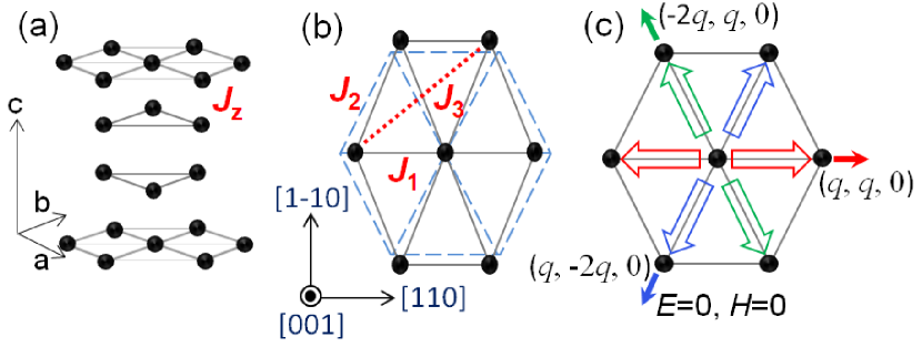
The multiferroic CuCrO2 compound exhibits both PSS order at zero field, and cycloidal spiral order in applied magnetic fields. It is also an example of a system whose magneto-electric properties are tunable by both an electric and magnetic field Kimura2009b ; Soda2009a . This material crystallizes in the rhombohedral 3̄m structure, forming a triangular lattice of Heisenberg Cr3+ (3 S = 3/2) spins Kadowaki1990 ; Crottaza1996 ; Seki2008 . Along the c-axis, each triangular plane is rotated from its neighbors by 30 degrees and displaced such that the atoms of one layer reside in the center of triangle of the neighboring layers. The structure of the Cr atoms is shown in Fig. 1 (a).
Thermodynamic investigations for single crystal samples of CuCrO2 reveal that two successive magnetic transitions occur at = 24.2 K and = 23.6 K, and nonzero P appears below Kimura2008 . The magnetic structure of CuCrO2 at zero magnetic field has been identified by neutron diffraction studies as an incommensurate PSS spin order of the Cr S = 3/2 moments with a propagation vector = (0.329,0.329, 0) Poienar2009 ; Soda2009a ; Poienar2010 ; Soda2010 ; Kajimoto2010 . Within the spiral, the ordered moment reaches maximum values of 2.2 along [1-10] and 2.8 along [001] Frontzek2011 ; Frontzek2012 . Single-crystal neutron diffraction measurements reveal that the spin structure between and (where there is no ferroelectric order) is two-dimensional (2D) with short-range magnetic correlations along the c-axis Frontzek2012 . However, in the multiferroic state below , the magnetic structure becomes 3D with long-range correlations along c-axis Frontzek2012 . Analysis of the magnetic excitation spectrum revealed antiferromagnetic (AFM) nearest- and next-nearest-neighbor exchange coupling within the plane and further showed that AFM next-next-nearest neighbor exchange couplings in the plane also have to be considered Frontzek2011 . Additionally, it was shown that a small ferromagnetic (FM) inter-plane coupling ( ) exists. The inter-plane interaction mediates the 3D-order in the multiferroic state and is responsible for the incommensurate q, deviating from the out-of-plane 120o spin structure (q = 4/3x) following the analysis of Ref. Rastelli1986 . The relevant exchange interaction paths are shown as a schematic cartoon in Fig. 1 (b). Finally, there is an easy-axis anisotropy along the c-axis.
There is a three-fold rotation symmetry with respect to the hexagonal c-axis, and thus there are six equivalent magnetic spiral domains, since the spiral propagation vector can point forward or backward along any of the three principle axes Frontzek2012 . Since the electric polarization points along the spiral propagation vector, there are also six electric domains as shown in Fig. 1 (c). These domains can be selected by applied electric and/or magnetic fields, and the application of both an electric and a magnetic field parallel to each other in the ab-plane are proposed to select a single domain Kimura2009b . A small lattice distortion was observed in the magnetically ordered phase by X-ray diffraction and magnetostriction measurements Kimura2009a . This distortion changes the equilateral triangles in the ab-plane into isosceles triangles (Fig. 1 (b)), thus impressing the lowered symmetry of the magnetic order of a given domain onto the lattice Kimura2009a . This distortion also induces an anisotropy in the ab-plane that is selected by the spiral propagation vector. Frontzek2011
By applying magnetic fields [1-10], the direction of P is changed from [110] to [1-10] at 5.3 T Kimura2008 ; Soda2009a ; Kimura2009b ; Yamaguchi2010 . Neutron diffraction measurements find that this change in the direction of P is accompanied by a spin flop in the magnetic domain whose spins originally lay perpendicular to the applied magnetic field. This spin flop corresponds to a transition from a proper-screw-spiral with [110] propagation vector to a cycloidal-spiral spin structure with a [1-10] propagation vector Soda2010 . According to the inverse-DM model, the cycloidal spiral could produce a P along [001], however in fact P in the cycloidal spiral state points along the propagation vector [1-10]. Furthermore, no feature in the magnetostriction is observed at this spin flop transition. Thus no inverse-DM interaction can be observed in this compound Kimura2009a and the multiferroic behavior appears to be dominated by the Arima mechanism Arima2007 .
In the present study, we extend the phase diagram of CuCrO2 to 65 T for all principle directions of H and P via measurements of magnetization and electric polarization in pulsed magnetic fields. We uncover additional magnetic and ferroelectric phase transitions.
II Experimental
Single crystals of CuCrO2 were grown by a flux method as described previously Frontzek2012 . The temperature and magnetic field dependence of the magnetization, , were measured in a commercial SQUID (superconducting quantum interference device) magnetometer in a Quantum Design (QD) Magnetic Property Measurement System (MPMS) up to = 7 T and down to = 2 K. The magnetization data taken in the superconducting magnet are consistent with earlier reports Kimura2008 ; Kimura2009b , where two magnetic transitions are detected in d/d at = 24.2 K and = 23.6 K and an anomaly is revealed in d/d curves around 5.3 T along H [1-10]. In addition, measurements were extended up to = 60 T and down to = 0.6 K in short-pulsed magnets with an extraction magnetometer Detwiler2000 at the National High Magnetic Field Laboratory (NHMFL) at Los Alamos National Laboratory. The magnetization curves taken in pulsed magnetic field are calibrated by the SQUID data.
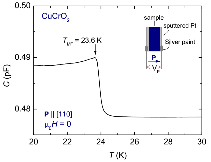
For the measurements of electric polarization and capacitance, samples were cut into thin plates with dimensions of 0.551.170.15 mm3 for P [110], 0.580.970.31 mm3 for P [1-10], and 0.891.120.38 mm3 for P [001]. The measurements for P in the ab-plane were consistent across three different samples. Platinum electrodes were sputtered onto the samples and then the platinum wires were attached onto the opposite faces of the thin plate (see the inset of Fig. 2). The samples were characterized by temperature-dependent capacitance measurements with an AH 2500 Capacitance Bridge at 1 kHz. In zero magnetic field, the phase transitions are seen in capacitance measurement as shown in Fig. 2, where a distinct peak structure is observed at = 23.6 K. The magnetic susceptibility measurements show two transitions, and , whereas capacitance measurements only show the phase transition.
The electric polarizaton in pulsed magnetic fields up to 65 T was measured by integrating the magnetoelectric current induced by changing magnetic fields, recorded using a Stanford Research 570 current to voltage converter Zapf2010 ; Zapf2011 . The magnetoelectric current is the magnetic field-induced analog of the pyroelectric current, and it increases linearly with magnetic field sweep rate such that the signal-to-noise of the electric polarization measurements is improved in our pulsed magnets compared to our DC magnets. Electric polarization was measured after first poling the sample by applying a constant external 200 V across the capacitor plates as the sample is cooled from 30 K to the measurement temperature. This corresponds to a poling electric field of 1.3 MV/m for P [110] and 0.6 MV/m for P [1-10] and [001].
III Results
III.1 Magnetization
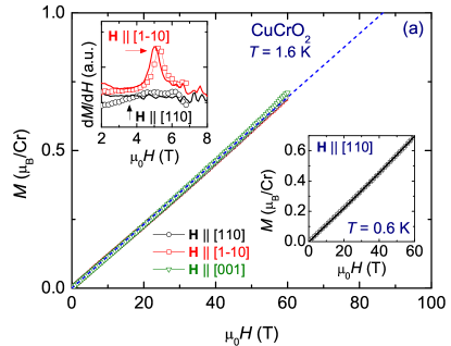
Magnetization of CuCrO2 in DC and pulsed fields are shown in Fig. 3. In Fig. 3 (a) to 60 T is plotted at 1.6 K, and is roughly linear to 60 T with no significant magnetic anisotropy between the three orientations of the magnetic field. No hysteresis is seen either, as shown in the right lower inset where for up- and down sweeps of [110] is plotted for K. reaches 0.7 /Cr at 60 T and the expected saturation magnetization of /Cr linearly extrapolates to T. A slight deviation from a linear dependence of is observed for 48 T along H [001]. Note that, for H [110], the observed magnetization curve is consistent with an earlier measurement at 1.6 K up to 50 T in pulsed magnetic field Yamaguchi2010 .
In the upper inset of Fig. 3 (a), we show a feature in d/d at 5.3 T and 2 K for H [1-10], corresponding to the spin flop at from a PSS to a cycloidal spiral structure, consistent with earlier results Kimura2009b .
The temperature evolution of the curves for H [001] and [110] are plotted in Fig. 3 (b) and (c) at selected temperatures. The general behavior of the curves remains the same for different temperatures, although curves show an increase in the slope with increasing temperature as the influence of the antiferromagnetic exchange interaction weakens.
III.2 Electric Polarization at 4 K
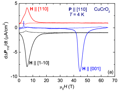
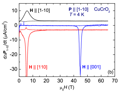
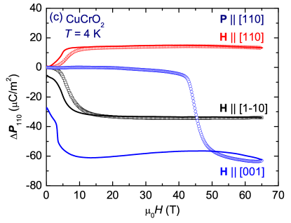
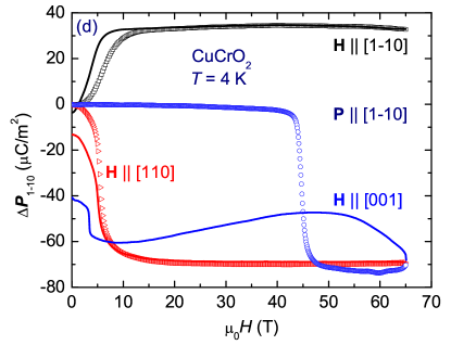
In Figs. 4 and 5 we show the measured magnetoelectric current d()/d and its integral, the magnetic field-induced change in electric polarization, of CuCrO2 at = 4 K. The temperature evolution of is shown in Figs 6, 7, and 8.
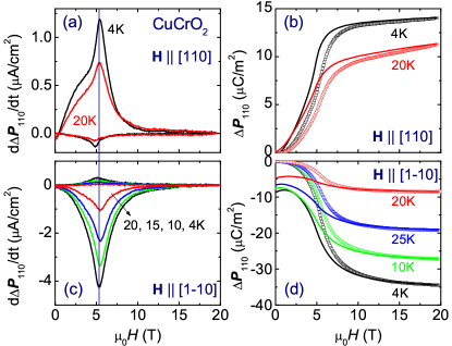
When H is applied in the ab-plane in Fig. 4 ( [1-10] and [110]), we observe transitions in near 5.3 T that are consistent with earlier results, and have been attributed to a spin-flop of one magnetic domain from PSS to cycloidal order Kimura2009b . This transition occurs both for and to H. In these transitions, the electric polarization always becomes larger along the direction of the applied , and smaller perpendicular to . For magnetic fields above this transition, we find that P remains constant, but nonzero, up to 65 T.
When H is applied along [001] (Fig. 4), we observe a previously unreported anomaly in for [110] and [1-10]. The electric polarization is extraordinarily hysteretic; it is suppressed at 45 T on the up sweep, and then regains most of its original value in a step near 3 T on the down sweep. Similar behavior was observed in three different samples.
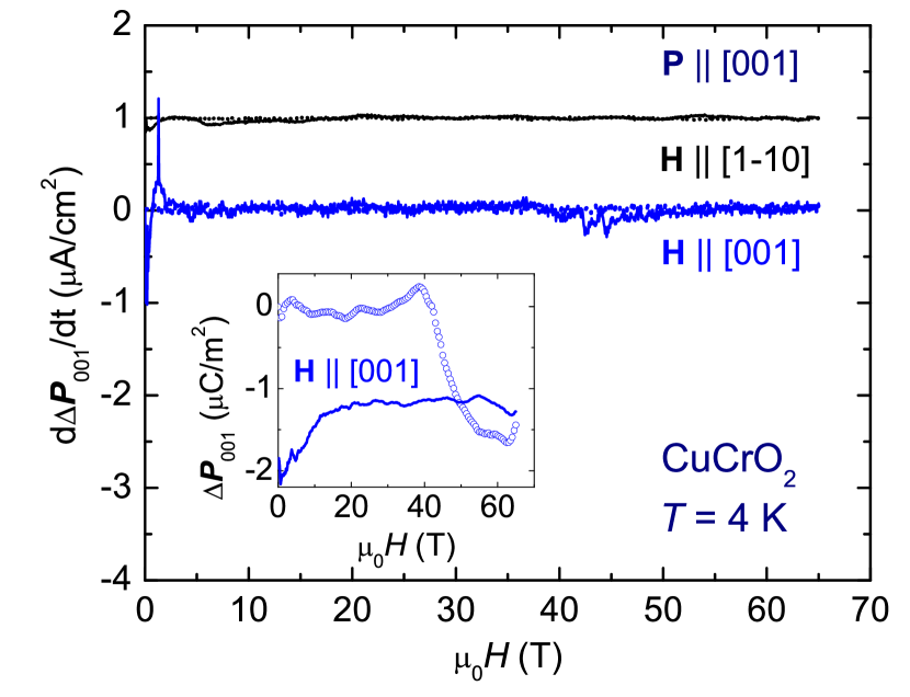
For P [001], for both and is insensitive to the entire magnetic field range measured as shown in Fig. 5. This observation is consistent with earlier reports Kimura2008 ; Kimura2009b that in zero magnetic field the electric polarization is absent along P [001]. We observed a very small change of for H [001] near 1.5 and 40 T, as shown in the inset of Fig. 5. However, the variation is an order of magnitude smaller than that for other orientations of P. We are assuming that the [110] and P [1-10] components are intrinsic whereas the small [001] component is due to a slight misalignment of the electrode. Therefore, the electric polarization vectors in CuCrO2 are lying within ab-plane in applied magnetic field at least up to 65 T. Details about the variation of as a function of temperature for [110] and [1-10] are described next.
III.2.1 Temperature-dependence of for H [110] and [1-10]
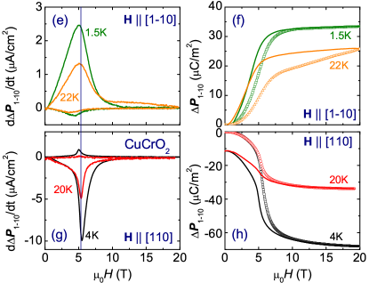
Previous works have discussed the electric polarization flop from P [110] to P [1-10] by application of magnetic field T along H [1-10]. However, details about the temperature variation have not been reported. We find that is insensitive to temperature from 1.6 K all the way to K, and in our pulsed field measurements is also insensitive to the direction of magnetic field in ab-plane. Figures 6 (a-d) and (e-h) show the curves for P [110] and P [1-10], respectively, at selected temperatures. Although the absolute value of the is suppressed with increasing temperature, the peak position in d/d remains the same for all measured temperatures.
The observed curves show a large hysteresis, which is enhanced as the temperature is lowered, and has been attributed to the first-order nature of the phase transition Kimura2009b . Interestingly, for the down sweep of magnetic field, the curves come back to zero for , whereas the curves do not come back to zero for . Note that this behavior with a large hysteresis loop is absent for the electric polarization measurements in superconducting magnets Kimura2009b , where the curves are back to zero with narrow region of hysteresis for both configurations of magnetic field. The observed behavior in pulsed magnetic field might be related to the domain dynamics that can be affected by magnetic field sweep rate.
III.2.2 Temperature-dependence of for H [001]
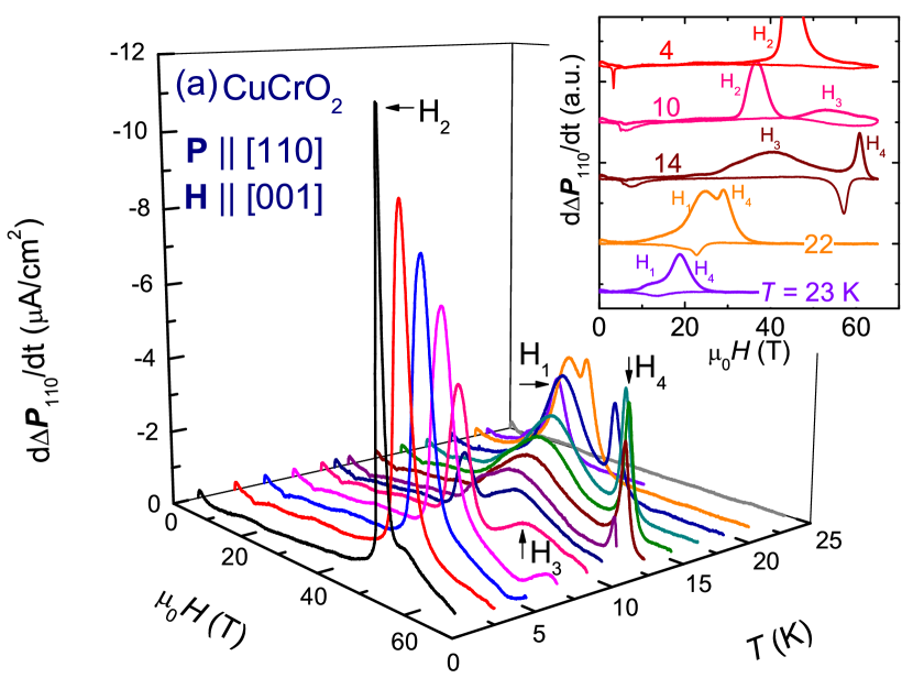
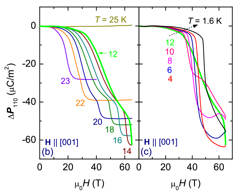
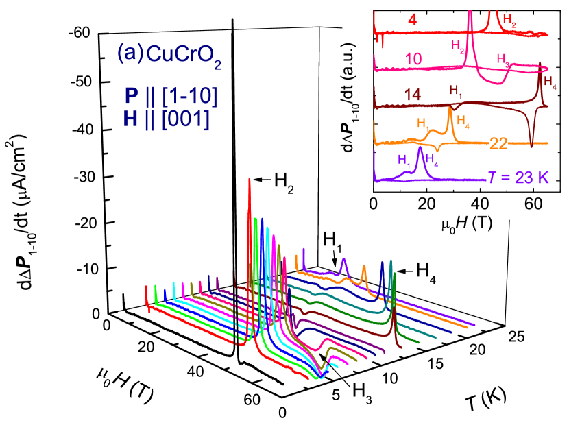
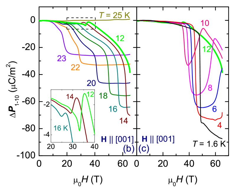
Figures 7 and 8 show the temperature evolution of P [110] and P [1-10] along H [001] at selected temperatures. For P [110], a 3D plot of d/d as a function of and is shown in Fig. 7 (a), and the integrated is shown in Figs. 7 (b) and (c).
At the base temperature there is one transition in the electric polarization on the up sweep at T, and a transition of almost equal size at = 3 T on the down sweep. Note that in the raw d/d data, these features appear to have different sizes due to the different magnetic field sweep rates on the up- and down sweep. As the temperature is increased, shifts to lower magnetic fields, and then additional features at higher fields appear on the up sweep, marked , and . Presumably and occur above 65 T at base temperature, and then shift down to 65 T as the temperature is increased. As the temperature is raised towards , the hysteresis between = 45 T and = 3 T narrows until both become 18 T just below . The integrated electric polarization in Figs. 7 (b) and (c) shows step-like features corresponding to the peaks in d/d, and actually becomes non-monotonic in for = 4, 6, and 8 K.
For P [1-10], d/d and are very similar to the previously-discussed case for P [110], also showing these additional anomalies at high temperatures (see Fig. 8). One difference is that the peak is negative for P [1-10], whereas it is positive for P [110]. The resultant is extremely non-monotonic between 4 and 20 K.
IV Phase Diagrams and Discussion
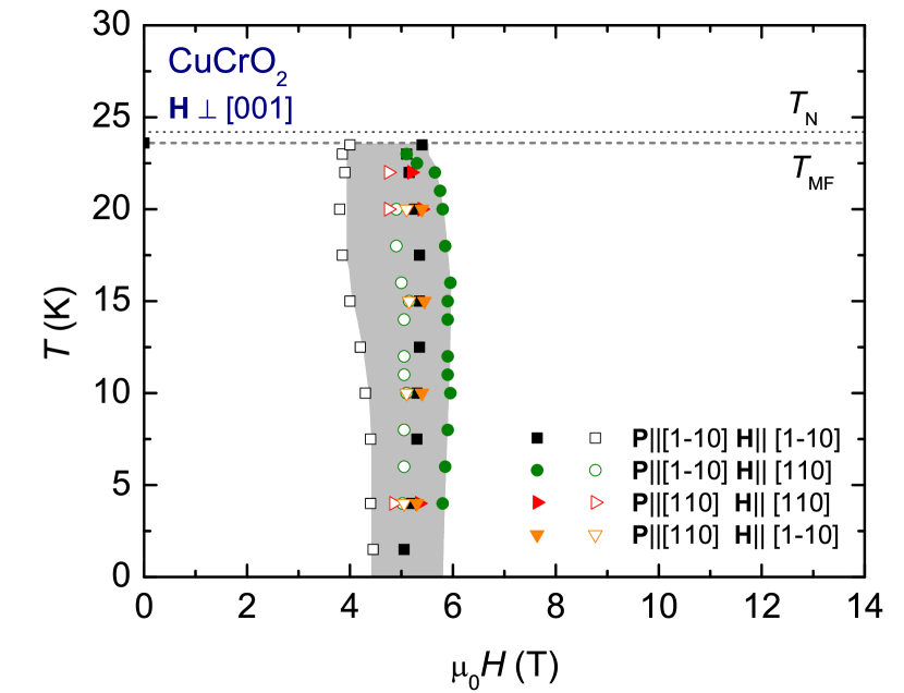
Our phase diagram of CuCrO2 for H in the ab-plane is shown in Fig. 9. The phase boundary was determined from the peaks in d/d. For , the system becomes a correlated paramagnet below = 24.2 K, and forms a 3D magnetic spiral structure with ferroelectricity below = 23.6 K Frontzek2012 . There is no P along the c-axis. For both directions of P in the ab-plane, P is enhanced when and suppressed when . The previously-reported PSS to cycloidal spiral phase transition, , observed in DC measurements near T when in the ab-plane Kimura2009a is shown as a star in Fig. 9. Our pulsed-field data also show features at and we find that is independent of temperature up to . Although the location of the phase transition is consistent between pulsed and DC magnetic field experiments, the shape of at the phase transition differs. For DC magnetic field measurements, a very sharp first-order transition at is observed in and dielectric constant, , along H [1-10], whereas a gradual transitions in and are observed for [110]. This behavior was explained by gradual domain rearrangement Kimura2009b . In pulsed magnetic field measurements, varies more gradually up to 10 T for all configurations we measured. In addition, exhibits a very large hysteresis loop compared to DC magnetic field measurements, and does not return to its zero-field value for . This discrepancy is probably due to the dynamics of the domain structure in CuCrO2. However, this effect does not change our main results. Since agrees between DC and pulsed magnetic fields, the essentials of the different ferroelectric phases remain the same. The magnetization in pulsed magnetic fields is similar to the DC magnetic field measurements as shown in the inset of Fig. 3 (a), where the peak height and width in d/d are similar between two different measurements. This is likely because the longitundinal magnetization results from spin canting within all of the domains, and thus is less sensitive to the domain dynamics.
Previous studies of CuCrO2 suggest Kimura2008 ; Soda2010 that the polarization flop at in CuCrO2 can be interpreted as the rearrangement of multiferroic domains. The present observations can be explained by the same approach. In zero applied electric field, there are six possible ferroelectric domains as shown in Fig. 1 (c). If the poling electric field E is applied along [110], the three ferroelectric domains closest to [110] are selected. By applying sufficiently high magnetic field, , all three domains will transform into the one domain parallel to q for H [110] and into the one domain perpendicular to q for H [1-10]. When the poling electric field E is applied along [1-10], two ferroelectric domains are selected. For , these two domains will collapse into the single domain parallel to q for H [110] and into the single domain perpendicular to q for H [1-10], respectively. Thus, P increases for and decreases for . In Ref. Soda2010 , the neutron scattering experiments have shown that the domain undergoes spin-flop for , when [110] and [1-10].
Within the cycloidal phase above , P is remarkably insensitive to , despite the linearly-increasing magnetization between 10 and 65 T. However, it is not so remarkable when we consider that 65 T corresponds to only about a quarter of the saturation magnetization, and also that in most magneto-electric materials, especially those with magnetostrictive coupling mechanisms, the leading term in the expansion of is . Since changes by only 1/6 of it’s value between 10 and 65 T, should only change by 1/36 of its value. Given that the electric polarization is induced by SIS-breaking magnetic order, we expect that the electric polarization can be suppressed some time before reaching the full saturation magnetization in a 270 T applied magnetic field.
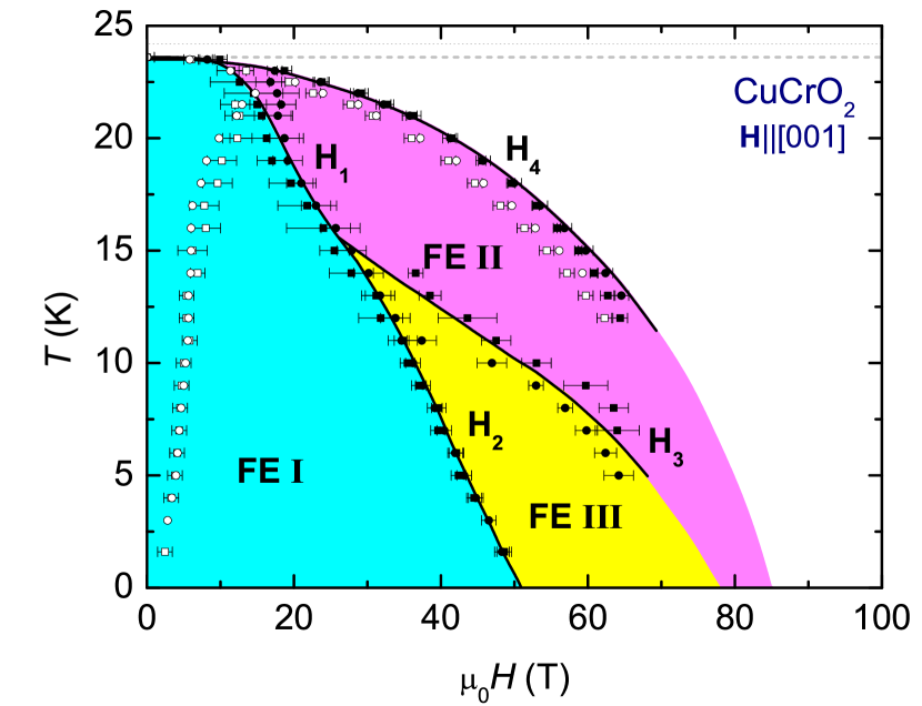
In Fig. 10, the phase diagram is shown for along the c-axis obtained from for P [110] and P [1-10]. The lines are defined by the peak positions in d/d, and different transitions for up- and down sweeps are shown.
The spin-flop transition observed for in the ab-plane of 5.3 T would also be expected to occur for along the c-axis, although at a different magnetic field due to magnetic anisotropy. Thus we can speculate that the 45 T transition () observed for along the c-axis is the same PSS to cycloidal spiral transition that occured at 5.3 T for in the ab-plane. This speculation is also in agreement with the observed hysteresis. For the down sweep of the magnetic field, an increase of the polarization is observed around 5 T, but the complete initial polarization is not recovered. This can be understood by considering that the initial state was mainly a one-domain state because the sample was prepared by cooling in an electric field. However, on the down sweep of magnetic field, the cycloidal phase decays into a 3-domain PSS state, resulting in less along the measured direction.
The assorted transitions observed in for different directions of P and H are only weakly observable in the mostly-linear curves up to 65 T. In light of previous neutron diffraction measurements, we conclude that the difference between the and curves can be related to the fact that results largely from domain physics of domains that have little net magnetization Soda2009a ; Soda2010 whereas the measured longitudinal is likely the result of spin canting that occurs in all domains.
Finally, we compare CuFeO2 and CuCrO2, both of which have multiferroic properties that have been explained by the mechanism proposed by Arima Arima2007 . They have the same crystal structure, where the magnetic Fe and Cr ions are located on triangular lattice planes stacked along c-axis. The MF phase in CuFeO2 is observed in an applied magnetic field between critical fields (7 and 13.5 T) or through doping. By contrast, the CuCrO2 is multiferroic at zero magnetic field. In addition, we observed in this study that the multiferroic phase in CuCrO2 can be suppressed by applied magnetic fields H [001]. Whereas the inter-plane coupling in CuCrO2 is ferromagnetic, the inter-plane coupling in CuFeO2 is antiferromagnetic, and non-frustrated. The nearest neighbor intra-layer exchange interaction is one order of magnitude stronger in CuCrO2 than CuFeO2 Frontzek2011 . Therefore, the critical field for the suppresion of the multiferroic phase in CuCrO2 is much larger than the critical fields in CuFeO2.
A theoretical work Fishman2011 has examined CuCrO2 using a simplified two dimensional triangular lattice AFM considering intralayer exchange parameters up to 3rd neighbor, but setting interlayer interactions to zero. This model qualitatively reproduces our phase diagrams, but does not predict the details we observe for H [001] (Fig. 10). In this model, the next stable magnetic state in applied magnetic fields is a three-sublattice phase with = 1/3 . At this phase transition, there is predicted to be a magnetization plateau, and the complete suppression of the electric polarization. If the prediction of this collinear three-sublattice phase is correct, then we can extrapolate from our magnetization data that the transition should occur at 90 T. Based on the model, the magnetic structure is always in a three-sublattice spiral state for all our measurements up to 65 Telsa. When we interpret the transitions as the spin-flop to the cycloidal state, then the emerging phase between and is especially interesting. Here, the magnetic structure is still a PSS, but with a strongly-reduced electric polarization. The applied magnetic field couples in the c-direction to the ferromagnetic interlayer exchange interaction. The stronger interlayer exchange might lead to new stacking sequence with a c-component of 1/2 in the propagation vectors. According to Ref. Rastelli1986 this would subsequently change the propagation vector from (1/3 - , 1/3 - , 0) to (1/3 - , 1/3, 1/2).
V Summary
The phase diagram of single crystalline CuCrO2 is explored up to 60 T in magnetization and 65 T in electric polarization for all the principle directions of P and H. At low temperatures, ferroelectricity persists beyond 65 T for all directions of P and H (except for [001], that shows no ferroelectricity for all H). We find that the curves for [001] reveal a complex new phase diagram with features on the up sweep of the magnetic field. We speculate that magnetic fields along the c-axis induce a PSS to cycloidal transition. At lower temperatures a non-monotonic evolution of the electric polarization with field could be consistent with the spiral wave vector stretching through incommensurate and commensurate wave vectors. On the other hand, for H in the ab-plane, we observe the previously-reported spin flop transition to a cycloidal spiral magnetic phase near 5.3 T, and find that it is not sensitive to temperatures between 1.6 K and the ordering temperature at K. We find that the electric polarization remains essentially constant between and the maximum magnetic field of 65 T.
The curves reveal a quasi-linear isotropic magnetic field dependence up to 60 T, with very weak signature of the spin-flop transition for H along [1 -1 0] at 5.3 T, and possibly a faint upward deviation from linear behavior at the 45 T transition for H along [001]. The magnetization value at 60 T reaches 0.7 /Cr, which is far below the saturation value. By a simple linear extrapolation, any 1/3 plateaus should occur near 90 T, and complete saturation by 270 T.
CuCrO2 shows strong magnetic frustration due to its triangular spin configuration in the ab-plane, and this is evidenced by the discrepancy between the K 2-D ordering temperature and the 270 T saturation magnetization and 200 K Curie-Weiss temperature. Thus as is typical for frustrated systems we observe multiple magnetic and ferroelectric phases accessibly by relatively small magnetic fields relative to the saturation magnetic field. However, within most of the phases there is almost no observable variation of the electric polarization with magnetic field. This may be due to the fact that in most type-two multiferroics, the leading behavior of is , and so will show most of its magnetic field-dependence at higher magnetic fields that we have applied.
In conclusion, CuCrO2 is a frustrated magnet with a rich variety of magnetic and ferroelectric phases that couple to each other and extend beyond 65 T.
Acknowledgements.
We thank Neil Harrison for the loan of his extraction magnetometer, and valuable discussions with Cristian Batista. Work at the NHMFL was supported by the US National Science Foundation through Cooperative Grant No. DMR-1157490, the State of Florida, and the US Department of Energy. Measurements at LANL were also supported by the Department of Energy’s Laboratory Directed Research and Development program. A. P. and G. E. acknowledge funding by the Scientific User Facilities Division, Office of Basic Energy Sciences, US Department of Energy. The research leading to these results has received funding from the European Community’s Seventh Framework Programme (FP7/2007-2013) under grant agreement No. 290605 (PSIFELLOW/COFUND).References
- (1) T. Kimura, Annu. Rev. Mater. Res. 37, 387 (2007).
- (2) S.-W. Cheong and M. Mostovoy, Nature Mater. 6, 13 (2007).
- (3) M. Kenzelmann and A. B. Harris and S. Jonas and C. Broholm and J. Schefer and S. B. Kim and C. L. Zhang and S.-W. Cheong and O. P. Vajk and J. W. Lynn, Phys. Rev. Lett. 95, 087206 (2005).
- (4) Y. Takahashi and N. Kida and Y. Yamasaki and J. Fujioka and T. Arima and R. Shimano and S. Miyahara and M. Mochizuki and N. Furukawa and Y. Tokura, Phys. Rev. Lett. 101, 187201 (2008).
- (5) A. M. Shuvaev and V. D. Travkin and V. Yu. Ivanov and A. A. Mukhin and A. Pimenov, Phys. Rev. Lett. 104, 097202 (2010).
- (6) G. Lautenschläger and H. Weitzel and T. Vogt and R. Hock and A. Böhm and M. Bonnet and H. Fuess, Phys. Rev. B 48, 6087 (1993).
- (7) K. Taniguchi and N. Abe and H. Umetsu and H. Aruga Katori and T. Arima, Phys. Rev. Lett. 101, 207205 (2008).
- (8) K. V. Shanavas and Debraj Choudhury and I. Dasgupta and Surinder M. Sharma and D. D. Sarma, Phys. Rev. B 81, 212406 (2010).
- (9) S. A. Klimin and M. N. Popova and B. N. Mavrin and P. H. M. van Loosdrecht and L. E. Svistov and A. I. Smirnov and L. A. Prozorova and H.-A. Krug von Nidda and Z. Seidov and A. Loidl and A. Ya. Shapiro and L. N. Demianets, Phys. Rev. B 68, 174408 (2003).
- (10) M. Kenzelmann and G. Lawes and A. B. Harris and G. Gasparovic and C. Broholm and A. P. Ramirez and G. A. Jorge and M. Jaime and S. Park and Q. Huang and A. Ya. Shapiro and L. A. Demianets, Phys. Rev. Lett. 98, 267205 (2007).
- (11) T. Masuda and A. Zheludev and A. Bush and M. Markina and A. Vasiliev, Phys. Rev. Lett. 92, 177201 (2004).
- (12) D. Hüvonen and U. Nagel and T. Rõõm and Y. J. Choi and C. L. Zhang and S. Park and S.-W. Cheong, Phys. Rev. B 80, 100402(R) (2009).
- (13) G. Lawes and A. B. Harris and T. Kimura and N. Rogado and R. J. Cava and A. Aharony and O. Entin-Wohlman and T. Yildrim and M. Kenzelmann and C. Broholm and A. P. Ramirez, Phys. Rev. Lett. 95, 087205 (2005).
- (14) A. B. Harris and T. Yildirim and A. Aharony and O. Entin-Wohlman, Phys. Rev. B 73, 184433 (2006).
- (15) I. A. Sergienko and E. Dagotto, Phys. Rev. B 73, 094434 (2006).
- (16) H. Katsura, N. Nagaosa, A. V. Balatsky, Phys. Rev. Lett. 95, 057205 (2005).
- (17) S. Seki, H. Murakawa, Y. Onose, and Y. Tokura, Phys. Rev. Lett. 103, 237601 (2009).
- (18) T. Nakajima, S. Mitsuda, S. Kanetsuki, M. Yamano, S. Iwamoto, Y. Yoshida, H. Mitamura, Y. Sawai, M. Tokunaga, K. Kindo, K. Prokeš, and A. Podlesnyak, Phys. Rev. B 81, 014422 (2010).
- (19) K. Kimura, H. Nakamura, K. Ohgushi, and T. Kimura, Phys. Rev. B 78, 140401(R) (2008).
- (20) T. Arima, Journal of the Physical Society of Japan 76, 073702 (2007).
- (21) M. Soda, K. Kimura, T. Kimura, M. Matsuura, and K. Hirota, J. Phys. Soc. Jpn. 78, 124703 (2009).
- (22) K. Kimura, H. Nakamura, S. Kimura, M. Hagiwara, and T. Kimura, Phys. Rev. Lett. 103, 107201 (2009).
- (23) H. Kadowaki, H. Kikuchi, and Y. Ajiro, J. Phys.: Condens. Matter 2, 4485 (1990).
- (24) O. Crottaza, F. Kubelb, H. Schmida, J. Solid State Chem. 122, 247 (1996).
- (25) S. Seki, Y. Onose, and Y. Tokura, Phys. Rev. Lett. 101, 067204 (2008).
- (26) M. Poienar, F. Damay, C. Martin, V. Hardy, A. Maignan, and G. André, Phys. Rev. B 79, 014412 (2009).
- (27) M. Poienar, F. Damay, C. Martin, J. Robert, and S. Petit, Phys. Rev. B 81, 104411 (2010).
- (28) R. Kajimoto, K. Nakajima, S. Ohira-Kawamura, Y. Inamura, K. Kakurai, M. Arai, T. Hokazono, S. Oozono, and T. Okuda, J. Phys. Soc. Jpn. 79, 123705 (2010).
- (29) M. Soda, K. Kimura, T. Kimura, and K. Hirota, Phys. Rev. B 81, 100406(R) (2010).
- (30) M. Frontzek, J. T. Haraldsen, A. Podlesnyak, M. Matsuda, A. D. Christianson, R. S. Fishman, A. S. Sefat, Y. Qiu, J. R. D. Copley, S. Barilo, S. V. Shiryaev, and G. Ehlers, Phys. Rev. B 84, 094448 (2011).
- (31) M. Frontzek, G. Ehlers, A. Podlesnyak, H. Cao, M. Matsuda, O. Zaharko, N. Aliouane, S. Barilo, and S. V. Shiryaev, J. Phys.:Conds matter 24 016004 (2012).
- (32) E. Rastelli and A. Tassi, J. Phys. C: Solid State Phys. 19, L423 (1986)
- (33) K. Kimura, T. Otani, H. Nakamura, Y. Wakabayashi, and T. Kimura, J. Phys. Soc. Jpn. 78, 113710 (2009).
- (34) H. Yamaguchi, S. Ohtomo, S. Kimura, M. Hagiwara, K. Kimura, T. Kimura, T. Okuda, and K. Kindo, Phys. Rev. B 81, 033104 (2010).
- (35) J. A. Detwiler, G. M. Schmiedeshoff, N. Harrison, A. H. Lacerda, J. C. Cooley, and J. L. Smith, Phys. Rev. B 61, 402 (2000).
- (36) V.S. Zapf, M. Kenzelmann, F. Wolff-Fabris, F. Balakirev, Y. Chen, Phys. Rev. B 82, 060402(R), (2010).
- (37) V. S. Zapf, P. Sengupta, C. D. Batista, F. Nasreen, F. Wolff-Fabris, and A. Paduan-Filho, Phys. Rev. B 83, 140405(R) (2011).
- (38) P. Bak, Reports on Progress in Physics 45, 587 (1982).
- (39) W. Selke, Physics Reports 170, 213 (1988).
- (40) R. Fishman, J. Phys.: Condens. Matter 23, 366002 (2011).
- (41) Masahito Mochizuki and Nobuo Furukawa, Phys. Rev. Lett. 105, 187601 (2010).
- (42) H. Schmid, J. Phys.: Condens. Matter 20, 434201 (2008).
- (43) L. C. Chapon and P. G. Radaelli and G. R. Blake and S. Park and S.-W. Cheong, Phys. Rev. Lett. 96, 097601 (2006).