Dispersions of ellipsoidal particles in a nematic liquid crystal
Abstract
Colloidal particles dispersed in a partially ordered medium, such as a liquid crystal (LC) phase, disturb its alignment and are subject to elastic forces. These forces are long-ranged, anisotropic and tunable through temperature or external fields, making them a valuable asset to control colloidal assembly. The latter is very sensitive to the particle geometry since it alters the interactions between the colloids. We here present a detailed numerical analysis of the energetics of elongated objects, namely prolate ellipsoids, immersed in a nematic host. The results, complemented with qualitative experiments, reveal novel LC configurations with peculiar topological properties around the ellipsoids, depending on their aspect ratio and the boundary conditions imposed on the nematic order parameter. The latter also determine the preferred orientation of ellipsoids in the nematic field, because of elastic torques, as well as the morphology of particles aggregates.
I Introduction
Dispersions of colloidal particles in anisotropic solvents such as liquid crystals (LC) make up a new class of composite materials that was discovered at the end of the last century bury ; tere ; ruhw ; poul97 ; poul98 ; lube ; monda99 ; star99 . Since then, there has been a surge of activity in this area covering both fundamental as well as more applied issues star01 ; muse . In such systems the colloidal inclusions experience new interactions – the so-called elastic interactions – that do not exist in more usual colloidal dispersions made of isotropic solvents. These interactions are long ranged, anisotropic, and have an elastic character originating from the distortions of the LC intrinsic order in the vicinity of the inclusions. The amplitude and symmetry of these distortions, which cost elastic energy, are to a large extent controlled by the boundary conditions at the colloid-LC interface. The latter are defined by the LC anchoring conditions, i.e. the orientation and strength with which the LC molecules are bound to surfaces (liquid or solid). Boundaries therefore play a crucial role in LC colloids for they control the way the particles interact with each other, which has a direct impact on the physical properties of the system.
Most of the studies performed in the past 15 years focused on the properties of micrometer-sized spherical colloids dispersed in a nematic LC phase. The topological defects, the director topology, the (anisotropic) elastic interactions between inclusions and the influence of various boundary conditions as well as external fields were all extensively characterized tere ; ruhw ; poul97 ; poul98 ; lube ; monda99 ; star99 ; star01 ; muse ; gu ; grol ; skar_a ; skar_b ; loud01 ; fuku ; rama ; poul97b ; smal05 ; taka ; eska . The long range nature of elastic forces (inverse power laws) is responsible for the building of large-scale ordered assemblies (linear chains, 2D and 3D crystals), while topological defects mainly ensure stability of the system muse ; loud00 ; ravn ; ogny08 ; ogny09 ; nych . Typical pair interaction energies for colloidal sizes m are of the order , meaning that the resulting particles’ aggregates are insensitive to thermal fluctuations and remain stable over time.
Today, new effects and properties are being unveiled such as the newly coined “nematic braids” defects tkal11 or topological colloids senyuk:13 ; liu:13 . However, the dynamical aspects of such systems still remain largely unexplored despite a few recent studies lavr ; pish ; lint . Furthermore, the interest in the field is further boosted by the recent progresses made in synthesizing new model particles varying in size, shape, nature, structure (core-shell) and surface properties as reviewed in cham ; saca10 ; saca11 . Synergetic properties between the inclusions and the LC matrix are now being explored, with the long term objective of designing materials with extraordinary properties, such as those expected for metamaterials for instance liu11 .
Most of the foreseen applications require rather high particle volume fractions, i.e. or more. However, it is still a puzzling challenge today to achieve homogeneous colloidal dispersions with tunable interparticle separations at such high particle loads. Because of the very high interaction energy (), particles aggregate massively leading to macroscopic phase separations in most cases. Note however that spectacular rheological properties were recently discovered with a colloid-nematic LC composite where the particle volume fraction exceeded wood .
Tuning the LC anchoring properties at the particles surface is a worthy route to circumvent the outlined problem: indeed, low anchoring strengths (and hence low surface energies) allow for a partial relaxation of elastic deformations in the bulk, thereby decreasing the overall elastic energy of the system. With liquid inclusions, anchoring properties may be readily altered due to adsorbed surfactants and polymers poul98 ; lock . This is however not the case with solid inclusions which require specific grafting procedures of chemical groups at the particle surface. Use of photosensitive molecules may bring up new insights though, as shown in prat : the LC anchoring type can be dynamically and reversibly switched between normal and tangential anchoring states.
The particle size is another parameter to play with in order to modulate the anchoring properties, as reported previously volt ; koen09a ; toma ; star01 . Particles smaller (larger) than the typical length m, where is the (average) nematic elastic constant (pN) and the surface anchoring strength () pgg ; pier , tend to favor weak (strong) anchoring conditions with a low (high) cost in terms of elastic energy. Indeed, recent experiments with nanometer-sized inclusions revealed that pair interaction energies of just a few could be achieved in thermotropic nematics koen09b ; a promising result in view of the long term applications mentioned above.
An alternative strategy to achieve high particle loads consists in playing with the particle shape. Mondiot et al. indeed showed that ellipsoidal inclusions with tangential anchoring conditions tend “to go unnoticed” when dispersed in lyotropic nematics, provided they are elongated enough mondi . At small volume fractions (), the micrometer-sized ellipsoids align their long axis parallel to the local director and remain individually dispersed over long periods of time (several months). Similar observations were made for bacteria and gold nanorods embedded in other lyotropic nematic phases smal08 ; liu10 . However, in other experiments involving non-spherical inclusions in thermotropic nematics, aggregation occurs tkal08 ; lapo09 .
In the present work, we offer a thorough numerical analysis of the energetics of ellipsoidal particles embedded
in a nematic phase, complemented with some experimental observations. The overall objective is to gain insights
on the possibility of using both particle geometry and surface anchoring properties (tangential versus
homeotropic) in order to achieve homogeneous LC dispersions with a large amount of particles. Both single and
pairs of ellipsoids are considered together with various anchoring types and strengths at the LC-colloid
interface. The results show that, for a given anchoring strength, the nature of the anchoring controls the
orientation of ellipsoids with respect to the far-field director. Varying the anchoring strength and the
particle aspect ratio reveals peculiar director configurations and topological defects in the vicinity of the
inclusions, leading to metastable states in the free energy landscape. Numerically computed pair interaction
energies emphasize a significant influence of the anchoring strength on the morphology of particles’ aggregates.
The experimental observations qualitatively support the calculations.
II Landau-de Gennes model
Within the Landau-de Gennes (LdG) theory, nematic liquid crystals are characterised by a traceless symmetric order-parameter tensor with components and the corresponding LdG free energy functional is pgg
| (1) |
with and the bulk and elastic free energy densities, given by
| (2) | |||||
| (3) |
where depends linearly on the temperature and is usualy written as , with a material dependent constant and the supercooling temperature of the isotropic phase. and are positive (material dependent) constants, and and are phenomenological parameters which can be related to the Frank-Oseen (FO) elastic constants. The first integral in Eq. (1) is taken over the 3D domain, , occupied by nematic, while the second integral is over the surfaces (in our case the surfaces of the colloidal particles) and accounts for non-rigid anchoring conditions.
Depending on the anchoring conditions, various expressions are at our disposal to model the surface free energy density . In the case of homeotropic anchoring, we used the following simple quadratic function favouring monostable nematic ordering , i.e., with a well-defined director, scalar and biaxial order parameters Nobili.1992 :
| (4) |
where is the anchoring strength at the colloidal surface whereas describes the preferred surface nematic ordering defined by , where is the unit normal to the colloidal surface. is the bulk value of the scalar order parameter (see Supplementary Information (SI) for the definition). We model planar degenerate anchoring at the colloidal surfaces by the following surface potential Fournier.2005
| (5) |
where , . is the anchoring strength favoring tangential orientation of the director, and ensures the existence of a minimum for the surface scalar order parameter at . We assume for simplicity . We also introduce the dimensionless anchoring strength , where is some typical length scale related to the size of colloidal particle and is the Frank elastic constant for twist deformations. Relations between the Frank elastic constants and the phenomelogical parameters can be found in the SI together with additional material concerning our numerical procedure.
III Results and discussion
In this section, we provide a description of the results obtained through both numerical calculations and qualitative observations. We begin with an isolated micrometer-sized prolate ellipsoid embedded in a nematic domain prior to dealing with pairs of such particles. As aforementioned, we investigate the effects of particle aspect ratio, strength and nature of boundary conditions at the LC-colloid interface.
III.1 Single ellipsoid
III.1.1 Numerical computations
The case of spheres with strong homeotropic anchoring conditions and a homogeneous nematic director in the far
field, was thoroughly analyzed in the literature. Very briefly, a dipolar configuration, consisting in a
point-like hedgehog defect close to the sphere, was both computed and evidenced experimentally
ruhw ; poul97 ; poul98 ; lube ; star99 . A quadrupolar configuration, in which a disclination line encircles the
sphere at the equator – the so-called Saturn ring configuration – offers an alternate geometry to the dipolar
state tere ; ruhw ; monda99 ; star01 ; gu . Now, how is the director topology altered in cases of elongated
particles? We shall first consider a single ellipsoid with strong homeotropic anchoring conditions.
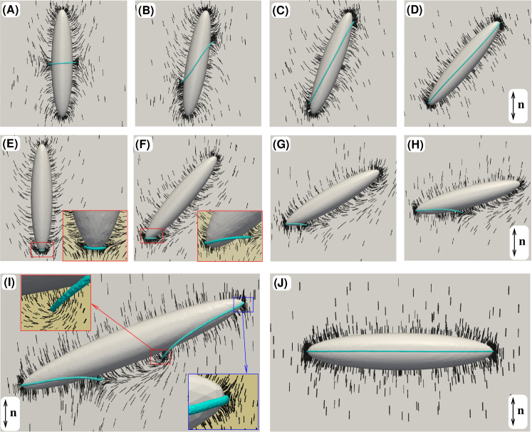
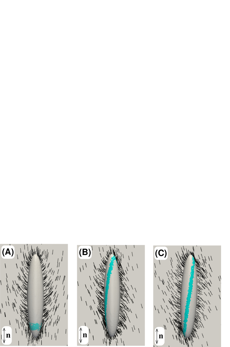
Strong homeotropic anchoring – Starting with various initial director configurations, we minimized the Landau-de Gennes free energy (Eq. (1)) according to the procedure described in the “Methods” section. Figs. 1A and E show two metastable configurations while Fig. 1J displays the most stable state. The former configuration (1A) consists in a disclination line that encircles the particle in its midplane when the ellipsoid long axis is parallel to . This topological defect is the analog of the Saturn ring defect encountered with spherical colloids and appears as a consequence of the conservation of the total topological charge in the nematic ruhw ; lube ; star99 . The obtained director topology, which we will call “midplane ring” in the following, is similar to that previously computed for rod-shaped objects andr ; hung and appear from an initial uniform director field.
The other configuration shown in Fig. 1E is a new director morphology which, as far as we know, was not predicted by previous simulations on rod-like objects. It consists of a small disclination ring located at one tip of the ellipsoid, which will be referred to as “tip ring” hereafter. Similarly to the midplane ring above, the tip ring carries a topological point charge equal to to ensure a zero global topological charge. The tip ring shows up from hedgehog or non-equatorial ring initial configurations of the director field. As we will see shortly, this topology has a lower energy than the midplane ring when the tilt angle, , is zero, i.e. the ellipsoid long axis is parallel to .
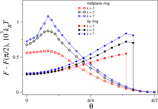
Unlike spheres, anisotropic particles will experience torques and hence adopt preferential orientations with respect to , as already reported mondi ; smal08 ; liu10 ; tkal08 ; andr ; hung ; lapo04 . We therefore computed the total free energy (Eq. (1)) as a function of for several aspect ratios and strong homeotropic conditions (dimensionless anchoring strength ; see the “Methods” section). The results are displayed in Fig. 2. Curves with open symbols correspond to midplane ring configurations (Fig. 1A-D), whereas curves with solid symbols refer to “tip ring” ones (Fig. 1E-H). In all cases, the global minimum occurs at (Fig. 1J), i.e. when the ellipsoid long axis is oriented perpendicularly to , but the configuration at enjoys some metastability, especially as increases. The metastable () and the stable () solutions are separated by a free energy barrier at . For a slight ellipsoid rotation away from , this free energy barrier may arise from a large elongation of the defect line and the corresponding increase of the line free energy (Fig. 1B,C), which, at such small values, is not counterbalanced by any relaxation of elastic distortions in the bulk. The total free energy of the system is indeed dominated by bulk director distortions. The height of the energy barrier grows with the ellipsoid aspect ratio (Fig. 2, open symbols) and amounts to for micron-sized particles with . As increases further, the above scenario reverses – the defect line still grows, but at a smaller “rate” and the additional line energy penalty does not prevent the total free energy to decrease steadily, via the relaxation of the bulk director distortions, all the way down to .
Tip rings configurations are more stable than midplane ones at small , but their free energy grows with . Tilting the particle away from indeed generates longer tip rings (see Fig. 1F-H) and the total free energy rises. Such conformations eventually loose their stability for as the corresponding energy branches suddendly fall down and join the ones computed for midplane rings (Fig. 2, solid symbols).
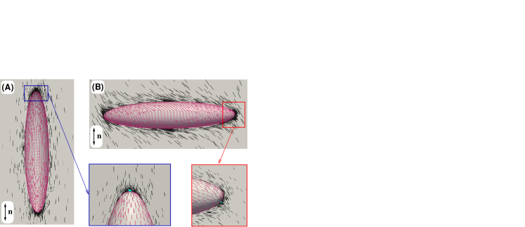
Besides midplane and tip rings, a surprising metastable double ring configuration also emerges out of the
computations, but only in a narrow range (rad) (see Fig. 1I).
The associated free energy curve (not shown) is always located above the curves computed for midplane and tip
rings. This double ring conformation has an interesting topological property. One of the rings (the bottom one
in Fig. 1I) has the director structure of a tip ring and therefore carries a topological point
charge equal to . Consequently, the second ring must have zero topological point charge. A fine inspection
of the director topology around the second loop reveals a hybrid structure composed of two parts characterised
by winding numbers equal to and . Insets in Fig. 1I show the details of
the director configurations around the (red box) and (blue box) disclination profiles. The
transition between the two proceeds by rotating the director by around an axis perpendicular to the
disclination line (see figure 2 in copar:13 ). Such a peculiar topology indeed yields zero topological
point charge, as explained in copar:13 .
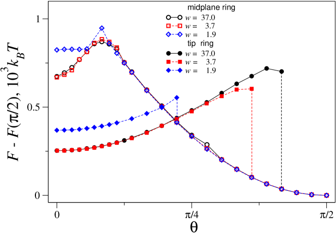
Weak homeotropic anchoring – Decreasing the (dimensionless) strength of the homeotropic anchoring
alters significantly the free energy landscape of an isolated ellipsoid, as shown in Fig. 3. For
midplane rings, weaker anchoring tends to suppress the energy barrier which separates the states and
. The angular domain of existence of tip rings shrinks from rad
() down to rad (). The surface director deviates more and more from the
local surface normal to minimize the bulk elastic distortions. In this case, the contribution from the surface
free energy increases and, correspondingly, that of the bulk free energy decreases. For even lower
values of (), tip rings and double rings no longer exist, the director field becomes nonsingular
and there is only one branch in the free energy which decreases monotonously from down to
(see dashed curve in Fig. 4). At , two director configurations are
possible (the difference in free energy is of the order of the numerical error), although they are both unstable
with respect to rotations. One of the configurations has a broken up-down symmetry (see
Fig. 5A) and is a remnant of the tip ring configurations. The second configuration,
shown in Fig. 5B, has the director structure reminescent of that of stretched midplane
rings (see Fig. 1C), but without disclination lines. Similar director configurations are also
obtained for , (Fig. 5C).
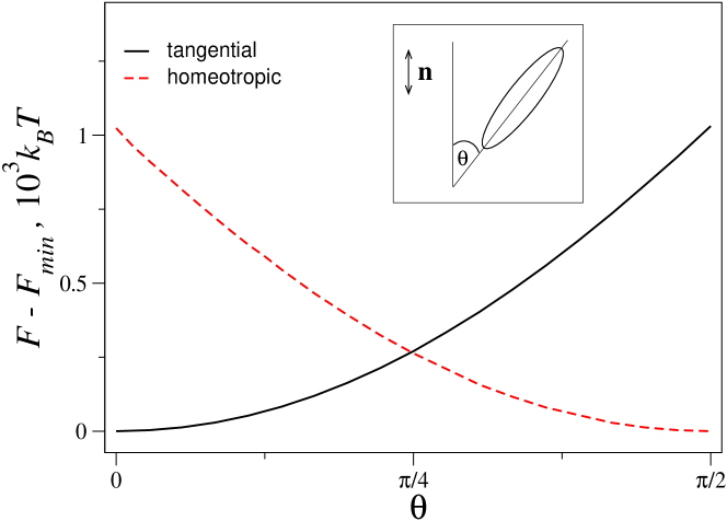
Tangential anchoring – Switching to tangential anchoring conditions yields a less rich behavior. Whatever the anchoring strength, be it strong () or weak (), the free energy curve always decreases monotonously from down to , which is the only stable state (Fig. 4). Hence, in this case, the ellipsoid will orient its long axis parallel to , in contrast to what is predicted for homeotropic anchoring. Therefore, the nature of the anchoring seems to control the preferential orientation of the ellipsoids in the nematic phase.
For strong tangential anchoring, the director field exhibits the typical surface defects known as boojums at the ellipsoid tips (see snapshot on Fig. 6). This configuration is similar to that computed in mondi using an approximate two-dimensional approach. For weaker anchoring (), the boojums disappear (not shown here).
Note that for strong tangential anchoring, a quadratic dependence of the elastic energy on for a
rod dispersed in a nematic was predicted broc and verified experimentally lapo04 . From
Fig. 4, it seems like such a law, i.e. , holds as well in the weak
anchoring regime (see the Supplementary Information for more details).
III.1.2 Experimental observations
In this paragraph, we briefly describe a few qualitative experiments that support the above numerical results. We mainly focus on the influence of the anchoring type at the LC-colloid interface.
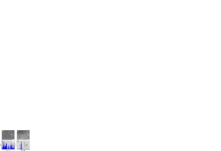
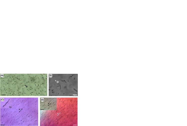
In a previous report mondi , we experimentally investigated the behavior of micrometer-sized prolate ellipsoids, of aspect ratio , embedded in a lyotropic phase consisting of an aqueous solution of rod-like micelles. For a given particle concentration (wt.%), it was shown that short- ellipsoids, just like spheres, aggregate and form anisotropic structures oriented at an angle with respect to the local background director, which are typical of quadrupolar elastic interactions. However, this is no longer the case when reaches a well-defined value (which depends on , as discussed further): above , the ellipsoids remain homogeneously dispersed and apparently do not interact one another, even over long periods of time (several months). This is recalled in Fig. 7B where the non aggregated ellipsoids () are aligned along the local director field, with a tangential anchoring of the rod-like micelles at the particles’ surfaces. The histogram of the angular distribution (see scheme in Fig. 7D) has indeed a well-marked peak along the nematic director contpg . However, this is not so when the same ellipsoids are embedded in the phase of the lyotropic system where the anchoring of the disk-like micelles is now homeotropic poul99 . On an average, the long axes of ellipsoids lie in planes oriented perpendicularly to . Within each plane, the orientation of each ellipsoid is random as is evidenced by the broad angular distribution histogram of Fig. 7C.
These observations agree qualitatively well with the calculations described above: the experiments confirm that the nature of the anchoring controls the ellipsoids’ average orientation with respect to the far-field director (see again Fig. 7 and Fig. 4).
Furthermore, in the phase, almost all ellipsoids have their long axes normal to
(Fig. 7A). If the anchoring were strong, a significant amount of particles should have been
observed with their long axes parallel to or slightly tilted, according to the metastable states
predicted by the computations (Figs. 2 and 3). No such metastable states exist in the
graph of Fig. 4 obtained in the weak anchoring regime, which is then more in line with the
experimental situation. Hence, these results suggest that the anchoring strength is probably weak in our
experiments. With given by (Supplementary Information) and taking the following values
, pN, m, , one can get an estimate of the anchoring
strength , which is a reasonable value for a weak anchoring case
lock ; pier ; lavr98 .
III.2 Pairwise interaction and collective behavior
We here provide a few additional experimental and computational results pertaining to a collection of ellipsoids.
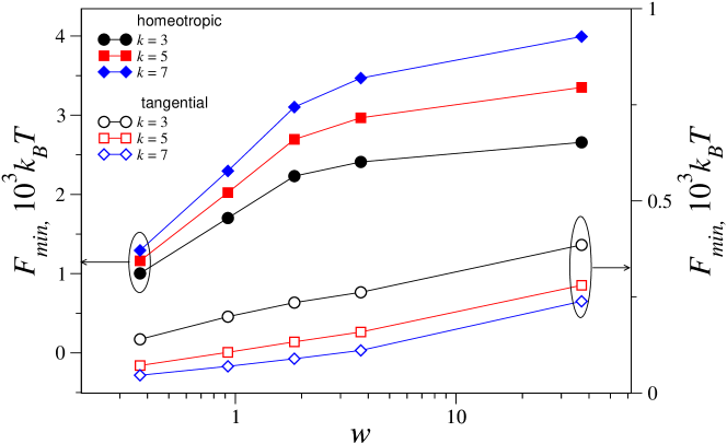
In the phase, our observations reveal that, whatever the aspect ratio , the ellipsoids cluster within comparable timescales than the starting microspheres at the same particle concentration (wt.%). This is shown in Fig. 8A,B where short chains of ellipsoids are oriented perpendicularly to , and within which the particles contact in a tip-to-tip manner. Consequently, it turns out that, in the phase, it is not possible to define a critical aspect ratio above which the ellipsoids can remain homogeneously dispersed, at least within the probed range. A possible explanation for this may be found by examining how the total free energy (Eq. (1)) of a single ellipsoid varies as a function of with homeotropic anchoring conditions (). Such a graph is plotted in Fig. 9 (solid symbols). Whatever the anchoring strength, the longer the ellipsoid, the higher the free energy cost. The length of the Saturn ring defect also increases with , but the defect core free energy always remains much smaller than the elastic free energy due to out-of-core director field distortions (results not shown). Hence, aggregation is expected for any and, as mentioned above, this is indeed observed experimentally.
This behavior differs drastically from that evidenced in the phase where the anchoring is tangential. Indeed, the graph on Fig. 9 (open symbols) now exhibits the opposite trend: as increases, the value of the free energy minimum decreases. The director topology only features boojums defects and no disclination loop (see Fig. 6). These computations strongly support previous calculations in 2D where the same trend was evidenced (see Fig. 3 in mondi ). Long- ellipsoids cost less free energy than short ones and therefore become easier to disperse in the nematic matrix because of weaker elastic distortions.
Overall, these results highlight again the importance of the anchoring type at the particle-nematic interface.
It is worth mentioning that structures similar to those exhibited in Fig. 8A,B were experimentally reported with cylinders tkal08 and theoretically predicted for spherocylinders hung in nematics with homeotropic anchoring conditions. In such studies, the director topology around the inclusions features a Saturn ring defect consisting in a disclination loop surrounding the particle long axis, which is normal to . Using the same anchoring type, our calculations also predict a Saturn ring defect which we have called midplane ring (Fig. 1A-D). But, as aforesaid, other peculiar director morphologies are possible (Fig. 1E-I).
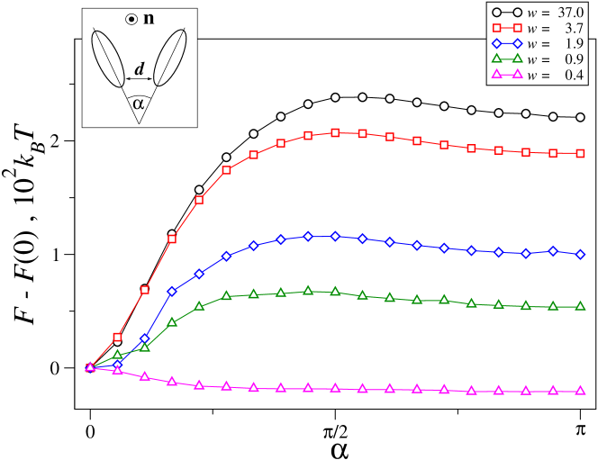
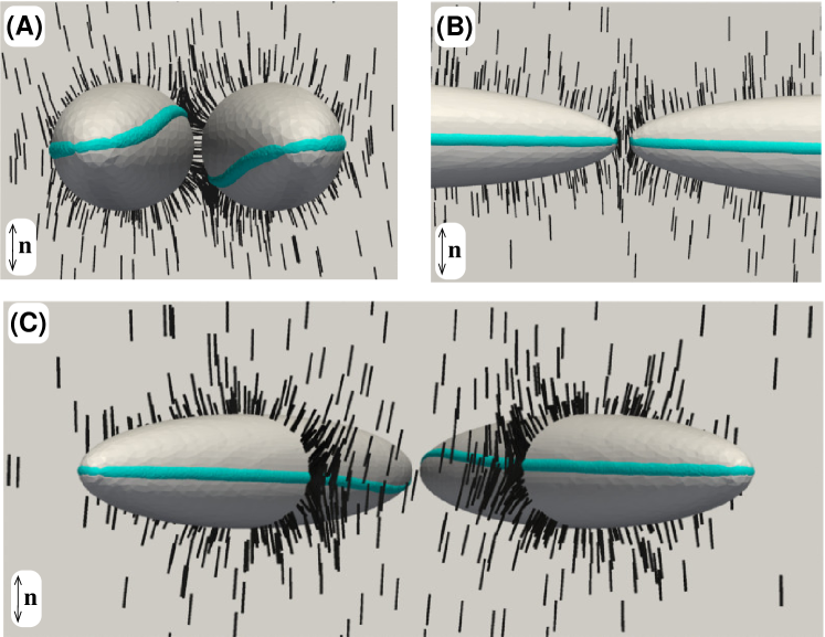
To gain further insights on the anisotropic structures reported on Fig. 8A,B, we have computed the effective pair interaction as a function of the relative colloidal orientation defined by angle (see Fig. 10 and inset). The calculations were carried out for a fixed surface-to-surface distance and several values of the homeotropic anchoring strength . It is found that strong anchoring favors the side-to-side configuration with . But the tip-to-tip configuration () seems to enjoy some metastability since the free energy curve is non monotonous and features a maximum around . As the anchoring strength decreases, so does the free energy difference between the side-to-side and the tip-to-tip configurations. For the lowest considered value of (), the free energy minimum is reached for the tip-to-tip geometry although the free energy values do not differ greatly for . The large repulsive “tails” of the interaction profiles for strong to moderate anchoring (Fig. 10) can be understood through an electrostatic analogy as the repulsion of two elastic quadrupoles poul97 ; lube . The emergence of the free energy barriers, and attractive forces at smaller values of , is due to the so-called defects sharing mechanism first described in tasinkevych:2002 . At small angular separations, the disclination lines in the inner regions start to deform in the opposite directions (see Fig. 11C), thereby minimizing the overall free energy and leading to the elastically bonded configuration at (see Fig. 11A). For weak anchoring, the free energy is dominated by the surface anchoring term, which is minimized for the tip-to-tip orientation (Fig. 11B). Experimentally, only tip-to-tip structures are observed, and therefore, these calculations again suggest that the anchoring of the micelles on the ellipsoids surfaces is probably weak. The same conclusion was indeed already inferred above when comparing the observations of Fig. 7 with the computations reported on Figs. 3 and 4. Finally, we note that the computed effective elastic forces acting upon ellipsoids in the side-to-side configuration (, strong anchoring) are of the order of pN, which correlates well with earlier experiments on micrometer-sized “homeotropic” spheres for which radial elastic forces of about pN were reported smalyukh:2005 .
Lastly, we have briefly investigated the effect of a four-fold increase of the particle concentration in the
phase, i.e. with wt.%. Ellipsoids with aspect ratios and 8.3 remained
well-dispersed for about three weeks. But one month after sample preparation, anisotropic chains parallel to
could be clearly distinguished as seen in Fig. 8C,D. Inside the chains, the ellipsoids
preferentially contact by their tips, like in the aggregates that form in the phase
(Fig. 8A,B). Hence, increasing leads to particle aggregation which is not too surprising
since the mean distance between inclusions decreases, thereby making them more sensitive to attractive elastic
interactions. However, the strength of these interactions was predicted to be a decreasing function of for
pairs of ellipsoids mondi . One may therefore surmise that the critical aspect ratio varies with
, and furthermore, that it is an increasing function of . However, a great deal of additional
experiments would be required to test this conjecture.
IV Conclusion
To conclude, we have studied through both numerics and experiments the static behavior of elongated particles embedded in a nematic phase. Among the most salient results of our investigation, let us point out that (i) the nature of the anchoring at the LC-colloid interface controls the preferential orientation of ellipsoids with respect to the far field nematic director, (ii) the strength of the anchoring has a direct impact on the packing geometry of pairs of ellipsoids, (iii) several metastable states exist in the free energy landscape when tilting the ellipsoid long axis with respect to ; some of these states exhibit unusual topological properties and director fields; and (iv) no “critical aspect ratio” could be evidenced in the phase: the ellipsoids are always found to aggregate whatever their aspect ratio, in fierce contrast to what was previously observed in the phase.
Our investigation therefore brings out additional insights about the influence of particle geometry on the
behavior of LC colloids. Optimising the shape of colloidal particles together with their surface properties is certainly a
worthy route to be explored further in view of achieving useful homogeneous LC dispersions with high particle
loads. On a more fundamental basis, composites such as LC colloids also provide an ideal playground to
deliberately nucleate various kinds of defects and study their interactions, which is of great interest from a
theoretical perspective alex .
V Methods
Preparation of particles. Prolate ellipsoidal particles were prepared using the process reviewed in
cham . Briefly, the latter consists in a uniaxial mechanical stretching of polymeric spherical particles
at constant volume, which are initially trapped in a film-forming polymer matrix. In our experiments, the matrix
was made of 89%-hydrolysed polyvinyl alcohol (PVA – from
Fluka©) whereas the starting particles consisted of m-diameter polystyrene (PS) beads
(Polysciences©). Monodisperse prolate ellipsoids of controllable aspect ratio ranging from 1
to 10 are easily achievable. We assume that the ellipsoids are cylindrically symmetric and defined by semi-axes
, where (resp. ) is the ellipsoid semi-long (resp. semi-short) axis. The resulting particles
are water-dispersable and aqueous suspensions may be stored for several months without significant aggregation.
However, despite numerous washing cycles, some PVA inevitably remains adsorbed at the particles surface.
Although we did not quantify this adsorption, we checked that PVA-coated PS spheres – i.e. spheres that
underwent the same preparation procedure as ellipsoids, but without the stretching step, – behaved like the
bare PS beads when dispersed in nematic phases as described below. Therefore, a PVA-coating had no effect on the
particles behavior, certainly because of the entropic nature of the anchoring in lyotropic nematics (see
hereafter).
Liquid crystal. We used a lyotropic liquid crystal system composed of sodium dodecyl sulfate (SDS),
decanol (DeOH) and water as the dispersing solvent for the ellipsoids. The phase diagram of this mixture
exhibits two nematic domains quist ; nesr : a calamitic nematic phase (), made of 9 nm-long and 3.6
nm-wide rod-like surfactant micelles; and a discotic nematic phase (), composed of 8 nm-diameter and 3.5
nm-thick disk-like micelles. We chose the following two compositions: one in the phase (water, 71%; SDS,
24.5%; DeOH, 4.5% by weight) and the other in the phase (water, 73%; SDS, 23.5%; DeOH, 3.5% by
weight). The phase was stable from C, the crystallisation temperature of SDS, up to C
where it transited to an isotropic micellar phase (). The phase transited to the phase
below C, and was stable over a large temperature range. Because of the high content of SDS, which is
at least 140 times the critical micellar concentration (CMC) of SDS
(M), the ionic strength of the nematic solutions is very high. As a
consequence, the electrostatic interactions are strongly screened. Indeed, with the above concentrations, the
debye screening length, , is of order nm pash ; monda96 . This estimate remains
valid for the two nematic domains of the ternary mixture since SDS concentrations range from 140 CMC up to about
200 CMC. Hence, the electrostatic repulsions are only effective at very short range, resulting in hard-core type
interactions between micelles and between micelles and walls. Orientation of anisotropic micelles close to walls
is then mainly driven by entropy: as shown previously, the micelles will tend to align parallel to surfaces to
minimize their excluded volume poni . This preferential alignment leads to tangential (resp. homeotropic)
anchoring of the micelles on surfaces in the (resp. ) phase. Tuning of the anchoring conditions may
then be achieved by introducing the particles either in the phase (tangential case) or in the phase
(homeotropic case) poul99 .
Samples.
Ellipsoids were suspended in nematic phases at mass fractions ranging from 0.01% to 0.06%. At such low
concentrations, the lyotropic nematic phases were not altered by the presence of the particles. Unlike
thermotropic nematic dispersions, no further chemical functionalization of the particles surface was required
here since the particles are water-dispersable. The nematic suspensions were put in 1 mm-thick optical glass
cells which were further capped and sealed to prevent evaporation. The samples were thermostated at C,
and observed using standard polarizing optical microscopy.
Acknowledgements
We acknowledge financial support from the French government, the Conseil Régional d’Aquitaine and
the Agence Nationale de la Recherche under grant No. PACTIS JC07-198199. M. T. acknowledges the 7th Framework
International Program Research Staff Exchange Scheme Marie-Curie Grant PIRSES-GA-2010-269181. Part of
this work was also done in the frame of the ITN-COMPLOIDS European network.
References
- (1) Burylov S. and Raikher Y. L. Orientation of a solid particle embedded in a monodomain nematic liquid crystal. Phys. Rev. E 50, 358-367 (1994).
- (2) Terentjev E. M. Disclination loops, standing alone and around solid particles, in nematic liquid crystals. Phys. Rev. E 51, 1330-1337 (1995).
- (3) Ruhwandl R. W. and Terentjev E. M. Monte Carlo simulation of topological defects in the nematic liquid crystal matrix around a spherical colloid particle. Phys. Rev. E 56, 5561-5565 (1997).
- (4) Poulin P., Stark H., Lubensky T. C. and Weitz D. A. Novel Colloidal Interactions in Anisotropic Fluids. Science 275, 1770-1773 (1997).
- (5) Poulin P. and Weitz D. A. Inverted and multiple nematic emulsions. Phys. Rev. E 57, 626-637 (1998).
- (6) Lubensky T. C., Pettey D., Currier N. and Stark H. Topological defects and interactions in nematic emulsions. Phys. Rev. E 57, 610-625 (1998).
- (7) Mondain-Monval O., Dedieu J. C., Gulik-Krzywicki T. and Poulin P. Weak surface energy in nematic dispersions: Saturn ring defects and quadrupolar interactions. Eur. Phys. J. B 12, 167-170 (1999).
- (8) Stark H. Director field configurations around a spherical particle in a nematic liquid crystal. Eur. Phys. J. B 10, 311-321 (1999).
- (9) Stark H. Physics of colloidal dispersions in nematic liquid crystals. Phys. Rep. 351, 387-474 (2001).
- (10) Muševič I., Škarabot M., Tkalec U., Ravnik M. and Žumer S. Two-Dimensional Nematic Colloidal Crystals Self-Assembled by Topological Defects. Science 313, 954-958 (2006).
- (11) Gu Y. and Abbott N. L. Observation of Saturn-Ring Defects around Solid Microspheres in Nematic Liquid Crystals. Phys. Rev. Lett. 85, 4719-4722 (2000).
- (12) Grollau S., Abbott N. L. and de Pablo J. J. Spherical particle immersed in a nematic liquid crystal: Effects of confinement on the director field configurations. Phys. Rev. E 67, 011702 (2003).
- (13) Škarabot M., Ravnik M., Žumer S., Tkalec U., Poberaj I., Babič D., Osterman N. and Muševič I. Two-dimensional dipolar nematic colloidal crystals. Phys. Rev. E 76, 051406 (2007).
- (14) Škarabot M., Ravnik M., Žumer S., Tkalec U., Poberaj I., Babič D., Osterman N. and Muševič I. Interactions of quadrupolar nematic colloids. Phys. Rev. E 77, 031705 (2008).
- (15) Loudet J.-C. and Poulin P. Application of an Electric Field to Colloidal Particles Suspended in a Liquid-Crystal Solvent. Phys. Rev. Lett. 87, 165503 (2001).
- (16) Fukuda J. and Yokoyama H. Stability of the director profile of a nematic liquid crystal around a spherical particle under an external field. Eur. Phys. J. E 21, 341-347 (2006).
- (17) Ramaswamy S., Nityananda R., Raghunathan V. A. and Prost J. Power-law forces between particles in a nematic. Mol. Cryst. Liq. Cryst. 288, 175-189 (1996).
- (18) Poulin P., Cabuil V. and Weitz D. A. Direct Measurement of Colloidal Forces in an Anisotropic Solvent. Phys. Rev. Lett. 79, 4862-4865 (1997).
- (19) Smalyukh I. I., Lavrentovich O. D., Kuzmin A. N., Kachynski A. V. and Prasad P. N. Elasticity-Mediated Self-Organization and Colloidal Interactions of Solid Spheres with Tangential Anchoring in a Nematic Liquid Crystal. Phys. Rev. Lett. 95, 157801 (2005).
- (20) Takahashi K., Ichikawa M. and Kimura Y. Force between colloidal particles in a nematic liquid crystal studied by optical tweezers. Phys. Rev. E 77, 020703(R) (2008).
- (21) Eskandari Z., Silvestre N. M., Tasinkevych M. and Telo da Gama M. M. Interactions of distinct quadrupolar nematic colloids. Soft Matter 8, 10100-10106 (2012).
- (22) Loudet J.-C., Barois P. and Poulin P. Colloidal ordering from phase separation in a liquid- crystalline continuous phase. Nature 407, 611 (2000).
- (23) Ravnik M., Škarabot M., Žumer S., Tkalec U., Poberaj I., Babič D., Osterman N. and Muševič I. Entangled Nematic Colloidal Dimers and Wires. Phys. Rev. Lett. 99, 247801 (2007).
- (24) Ognysta U., Nych A., Nazarenko V., Muševič I., Škarabot M., Ravnik M., Žumer S., Poberaj I. and Babič D. 2D Interactions and Binary Crystals of Dipolar and Quadrupolar Nematic Colloids. Phys. Rev. Lett. 100, 217803 (2008).
- (25) Ognysta U., Nych A., Nazarenko V., Škarabot M. and Muševič I. Design of 2D Binary Colloidal Crystals in a Nematic Liquid Crystal. Langmuir 25, 12092-12100 (2009).
- (26) Nych A., Ognysta U., Škarabot M., Ravnik M., Žumer S. and Muševič I. Assembly and control of 3D nematic dipolar colloidal crystals. Nat. Commun. 4, 1489 (2013).
- (27) Tkalec U., Ravnik M., Čopar S., Žumer S. and Muševič I. Reconfigurable Knots and Links in Chiral Nematic Colloids. Science 333, 62-65 (2011).
- (28) Senyuk B., Liu Q., He S., Kamien R. D., Kusner R. B., Lubensky T. C. and Smalyukh I. I. Topological colloids. Nature 493, 200-205 (2013).
- (29) Liu, Q. Senyuk, B., Tasinkevych, M. and Smalyukh I. I. Nematic liquid crystal boojums with handles on colloidal handlebodies. Proc. Natl. Acad. Sci. USA 110, 9231-9236 (2013).
- (30) Lavrentovich O. D., Lazo I. and Pishnyak O. P. Nonlinear electrophoresis of dielectric and metal spheres in a nematic liquid crystal. Nature 467, 947-950 (2010).
- (31) Pishnyak O. P., Shiyanovskii S. V. and Lavrentovich O. D. Inelastic Collisions and Anisotropic Aggregation of Particles in a Nematic Collider Driven by Backflow. Phys. Rev. Lett. 106, 047801 (2011).
- (32) Lintuvuori J. S., Stratford K., Cates M. E. and Marenduzzo D. Colloids in Cholesterics: Size-Dependent Defects and Non-Stokesian Microrheology. Phys. Rev. Lett. 105, 178302 (2010).
- (33) Champion J. A., Katare Y. K. and Mitragotri S. Making polymeric micro- and nanoparticles of complex shapes. Proc. Natl. Acad. Sci. USA 104, 11901-11904 (2003).
- (34) Sacanna S., Irvine W. T. M., Chaikin P. M. and Pine D. J. Lock and key colloids. Nature 464, 575-578 (2010).
- (35) Sacanna S. and Pine D. J. Shape-anisotropic colloids: Building blocks for complex assemblies. Curr. Opin. Colloid Interface Sci. 16, 96-105 (2011).
- (36) Liu Y. and Zhang X. Metamaterials: a new frontier of science and technology. Chem. Soc. Rev. 40, 2494-2507 (2011).
- (37) Wood T. A., Lintuvuori J. S., Schofield A. B., Marenduzzo D. and Poon W. C. K. A Self-Quenched Defect Glass in a Colloid-Nematic Liquid Crystal Composite. Science 334, 79-83 (2011).
- (38) Lockwood N. A., Gupta J. K. and Abbott N. L. Self-assembly of amphiphiles, polymers and proteins at interfaces between thermotropic liquid crystals and aqueous phases. Surf. Sci. Rep. 63, 255-293 (2008).
- (39) Prathap Chandran S., Mondiot F., Mondain-Monval O. and Loudet J.-C. Photonic Control of Surface Anchoring on Solid Colloids Dispersed in Liquid Crystals. Langmuir 27, 15185-15198 (2011).
- (40) Völtz C., Maeda Y., Tabe Y. and Yokoyama H. Director-Configurational Transitions around Microbubbles of Hydrostatically Regulated Size in Liquid Crystals. Phys. Rev. Lett. 97, 227801 (2006).
- (41) Koenig Jr. G. M., Ong. R., Cortes A. D., Moreno-Razo J. A., de Pablo J. J. and Abbott N. L. Single nanoparticle tracking reveals influence of chemical functionality of nanoparticles on local ordering of liquid crystals and nanoparticle diffusion coefficients. Nano Lett. 9, 2794-2801 (2009).
- (42) Tomar V., Roberts T. F., Abbott N. L., Hernández-Ortiz J. P. and de Pablo J. J. Liquid Crystal Mediated Interactions Between Nanoparticles in a Nematic Phase. Langmuir 28, 6124-6131 (2012).
- (43) de Gennes P. G. and Prost J., The Physics of Liquid Crystals, Clarendon Oxford 2nd Ed., 1993.
- (44) Pieranski P. and Oswald P., Liquid Crystals, GB Science Publishers, Paris, 2002.
- (45) Koenig Jr. G. M., de Pablo J. J. and Abbott N. L. Characterization of the Reversible Interaction of Pairs of Nanoparticles Dispersed in Nematic Liquid Crystals. Langmuir 25, 13318-13321 (2009).
- (46) Mondiot F., Prathap Chandran S., Mondain-Monval O. and Loudet J.-C. Shape-Induced Dispersion of Colloids in Anisotropic Fluids. Phys. Rev. Lett. 103, 238303 (2009).
- (47) Smalyukh I. I., Butler J., Shrout J. D., Parsek M. R. and Wong G. C. L. Elasticity-mediated nematiclike bacterial organization in model extracellular DNA matrix. Phys. Rev. E 78, 030701(R) (2008).
- (48) Liu Q., Cui Y., Gardner D., Li X., He S. and Smalyukh I. I. Self-Alignment of Plasmonic Gold Nanorods in Reconfigurable Anisotropic Fluids for Tunable Bulk Metamaterial Applications. Nano Lett. 10, 1347-1353 (2010).
- (49) Tkalec U., Škarabot M. and Muševič I. Interactions of micro-rods in a thin layer of a nematic liquid crystal. Soft Matter 4, 2402-2409 (2008).
- (50) Lapointe C. P., Mason T. G. and Smalyukh I. I. Shape-Controlled Colloidal Interactions in Nematic Liquid Crystals. Science 326, 1083-1086 (2009).
- (51) Nobili M. and Durand G. Disorientation-induced disordering at a nematic-liquid-crystal–solid interface. Phys. Rev. A 46, R6174-R6177 (1992).
- (52) Fournier J. B. and Galatola P. Modeling planar degenerate wetting and anchoring in nematic liquid crystals. EPL 72, 403-409 (2005).
- (53) Andrienko D., Allen M. P., Skačej G. and Žumer S. Defect structures and torque on an elongated colloidal particle immersed in a liquid crystal host. Phys. Rev. E 65, 041702 (2002).
- (54) Hung F. R. Quadrupolar particles in a nematic liquid crystal: Effects of particle size and shape. Phys. Rev. E 79, 021705 (2009).
- (55) Lapointe C. P., Hultgren A., Silevitch D. M., Felton E. J., Reich D. H. and Leheny R. L. Elastic Torque and the Levitation of Metal Wires by a Nematic Liquid Crystal. Science 303, 652-655 (2004).
- (56) Čopar, S. and Žumer S. Quaternions and hybrid nematic disclinations. Proc. R. Soc. A 469, 20130204 (2013).
- (57) Brochard F. and de Gennes P. G. Theory of Magnetic Suspensions in Liquid Crystals. J. Phys. (Paris) 31, 691 (1970).
- (58) The histograms of the angular distributions shown in Fig. 7 were built thanks to a standard video tracking program which fits the contour of the ellipsoids’ projection in the -plane. Some of the ellipsoids may be slightly tilted out of this plane, but it is neglected in our analysis.
- (59) Poulin P., Frances N. and Mondain-Monval O. Suspension of spherical particles in nematic solutions of disks and rods. Phys. Rev. E 59, 4384-4387 (1999).
- (60) Lavrentovich O. D. Topological defects in dispersed liquid crystals, or words and worlds around liquid crystal drops. Liq. Cryst. 24, 117-125 (1998).
- (61) Tasinkevych M., Silvestre N. M., Patrício P. and Telo da Gama M. M. Colloidal interactions in two-dimensional nematics. Eur. Phys. J. E 9, 341 (2002).
- (62) Smalyukh I. I., Kuzmin A. N., Kachynski A. V., Prasad P. N. and Lavrentovich O. D. Optical trapping of colloidal particles and measurement of the defect line tension and colloidal forces in a thermotropic nematic liquid crystal. Appl. Phys. Lett. 86, 021913 (2005).
- (63) Alexander G. P., Chen B. G., Matsumoto E. A. and Kamien R. D. Colloquium: Disclination loops, point defects, and all that in nematic liquid crystals Rev. Mod. Phys. 84, 497-514 (2012).
- (64) Quist P. O., Halle B. and Furó I. Micelle size and order in lyotropic nematic phases from nuclear spin relaxation. J. Chem. Phys. 96, 3875 (1992).
- (65) Nesrullajev A. Shape and sizes of micelles in nematic-calamitic and nematic-discotic mesophases: Sodium lauryl sulphate/water/decanol lyotropic system. Mater. Chem. Phys. 123, 546-550 (2010).
- (66) Pashley R. M. and Ninham B. W. Double-layer forces in ionic micellar solutions. J. Phys. Chem. 91, 2902-2904 (1987).
- (67) Mondain-Monval O., Leal-Calderon F. and Bibette J. Forces Between Emulsion Droplets: Role of Surface Charges and Excess Surfactant. J. Phys. II France 6, 1313-1329 (1996).
- (68) Poniewierski A. and Holyst R. Nematic alignment at a solid substrate: The model of hard spherocylinders near a hard wall. Phys. Rev. A 38, 3721-3727 (1988).