Study on Delaunay tessellations of 1-irregular cuboids for 3D mixed element meshes
Abstract
Mixed elements meshes based on the modified octree approach contain several co-spherical point configurations. While generating Delaunay tessellations to be used together with the finite volume method, it is not necessary to partition them into tetrahedra; co-spherical elements can be used as final elements. This paper presents a study of all co-spherical elements that appear while tessellating a 1-irregular cuboid (cuboid with at most one Steiner point on its edges) with different aspect ratio. Steiner points can be located at any position between the edge endpoints. When Steiner points are located at edge midpoints, 24 co-spherical elements appear while tessellating 1-irregular cubes. By inserting internal faces and edges to these new elements, this number is reduced to 13. When 1-irregular cuboids with aspect ratio equal to are tessellated, 10 co-spherical elements are required. If 1-irregular cuboids have aspect ratio between 1 and , all the tessellations are adequate for the finite volume method. When Steiner points are located at any position, the study was done for a specific Steiner point distribution on a cube. 38 co-spherical elements were required to tessellate all the generated 1-irregular cubes. Statistics about the impact of each new element in the tessellations of 1-irregular cuboids are also included. This study was done by developing an algorithm that construct Delaunay tessellations by starting from a Delaunay tetrahedral mesh built by Qhull.
1 Introduction
Scientific and engineering problems are usually modeled by a set of partial
differential equations and the solution to these partial differential equations
is calculated through the use of numerical methods. In order to get good results,
the object being modeled (domain) must be discretized in a proper way
respecting the requirements imposed by the used numerical
method. The discretization (mesh) is usually composed of simple cells (basic elements)
that must represent the domain in the best possible way.
In particular, we are interested in meshes for the finite volume method [1]
which are formed by polygons (in a 2D domain) or polyhedra (in a 3D domain),
that satisfy the Delaunay condition: the circumcircle in 2D, or circumsphere
in 3D, of each element does not contain any other mesh point in its interior [2].
The Delaunay condition is required because we use its dual structure, the Voronoi
diagram, to model the control volumes in order to compute an approximated
solutions. The basic elements used so far are triangles and quadrilaterals in
2D, and tetrahedra, cuboids, prisms and pyramids in 3D. Meshes composed of different
elements types are called mixed element meshes [3].
Mixed element meshes are built on 2D or 3D domains described by
sets of points, polygons or polyhedra depending on the application.
We have developed a mixed element mesh generator [4] based on an extension of
octrees [5, 6]. Our approach starts enclosing the domain in the smallest bounding box (cuboid). Second,
this cuboid is continuously
refined, at any edge position, by using the geometry information of the
domain. That is why this refinement is called intersection based approach. Once this step
finishes, an initial non-conforming mesh composed of tetrahedra, pyramids, prisms, and cuboids is generated
that fits the domain geometry.
Third, these elements are further refined by bisection, as far as possible,
until the density requirements are fulfilled. Fourth,
the mesh is done 1-irregular by allowing only one Steiner point on each edge.
The current solution is
based on patterns but only the most frequently used patterns are available. Then, if
a pattern is not available or the element can not be properly tessellated for the
finite volume method, new Steiner points are inserted until all 1-irregular
elements can be properly tessellated.
The current set of seven final elements is shown in Figure 1.
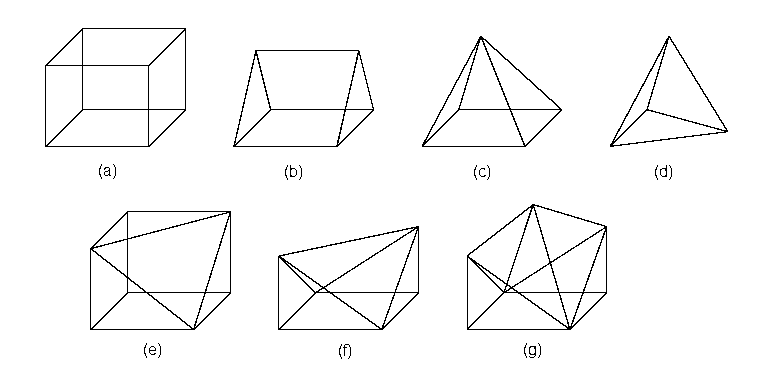
The advantage of using a mixed mesh in comparison with a tetrahedral mesh is that
the use of different element types reduce the amount of edges, faces and elements
in the final mesh. For example, we do not need to divide a cuboid into tetrahedra.
On the other hand, a disadvantage is that the equations must be discretized
using different elements.
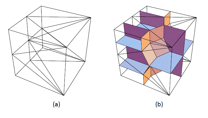
Octree based approaches naturally produces co-spherical point sets.
A mixed mesh satisfying the Delaunay condition can include
all produced co-spherical elements as shown in Figure 2.
The final elements in this example are five pyramids and four tetrahedra.
The goal of this paper is to study the co-spherical elements that can appear while
tessellating 1-irregular cuboids generated by using a bisection and intersection
based approach and to analyze how
useful would be to include the new elements in the final element set.
In particular, this paper gives the number and shape of new co-spherical
elements needed to tessellate (a) all 1-irregular cuboids generated by the
bisection approach and (b) some particular 1-irregular cuboids generated by the
intersection refinement approach. In addition, statistics
associated with particular tessellations are presented such as the frequency each co-spherical element
is used and the number of tessellations that can be used with the
finite volume method without adding extra vertices.
The analysis of the 1-irregular cuboid tessellations was done under different criteria that affect the amount of generated co-spherical elements.
We have focused this work on the analysis of the tessellations of 1-irregular
cuboids because this element
is the one that more frequently appears when meshes are generated by a
modified octree approach. A theoretical study on the number of different 1-irregular
cuboid configurations that can appear either by using a bisection or an intersection
based approach was published in [7]. We use the results of that work as starting point for this study.
This paper is organized as follows: Section 2
describes the bisection and intersection refinement approaches.
Section 3 presents briefly the developed algorithm to compute
Delaunay tessellations. Section 4 and Section 5 give the results
obtained by applying the algorithm to 1-irregular cuboids generated
by a bisection and an intersection based approach, respectively. Section 6 includes our conclusions.
2 Basic concepts
This section describes some ideas in order to understand how 1-irregular cuboids are generated.
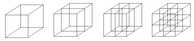
2.1 Bisection based approach 1-irregular configurations
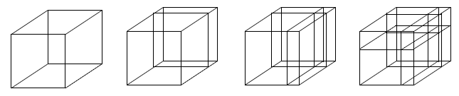
In this approach, the Steiner points inserted at the refinement phase are always located at the edge midpoints. Cuboids can be refined into two, four or eight smaller cuboids as shown in Figure 3.
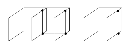
This refinement produces neighboring cuboids with Steiner points located at the edge midpoints. Those 1-irregular cuboids are larger than the already refined neighbor cuboid as shown in Figure 4.
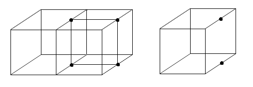
.
2.2 Intersection based approach 1-irregular configurations
While using an intersection based approach, the Steiner points are not necessarily located at the edge midpoints. In general, there are no constrains on the location of the Steiner points, except by the fact that parallel edges must be divided in the same relative position to ensure the generation of cuboids and not any other polyhedron. Figure 5 shows an example of this approach.
This refinement produces neighboring cuboids with Steiner points located at any edge position. Those 1-irregular cuboids are larger than the already refined neighbor cuboid as shown in Figure 4.
3 Algorithm
In order to count the number of new co-spherical elements than can appear and to
recognize their shape, we have developed an algorithm that executes the followings steps:
-
1.
Build the point configuration of a 1-irregular cuboid by specifying the coordinates of the cuboid vertices and its Steiner points.
-
2.
Build a Delaunay tetrahedral mesh for this point configuration by using QHull [8]111http://www.qhull.org.
-
3.
Join tetrahedra to form the largest possible co-spherical elements.
-
4.
Identify each final co-spherical polyhedron.
Qhull divides co-spherical point configurations into a set of tetrahedra by adding an artificial point that is not part of the input. Then, we use this fact to recognize the faces that form a co-spherical polyhedron and later to recognize which element is.
4 Results: Bisection based approach
This section describes the results obtained by applying the previous algorithm to the 4096 () 1-irregular configurations that can be generated using a bisection based approach. First, the new co-spherical elements are shown. Then, their impact in all the tessellations is analyzed and finally, the tessellations that can be used with the finite volume method are characterized.
4.1 New co-spherical elements
We have identified 17
new co-spherical polyhedra in the tessellations of 1-irregular cubes
in addition to the seven original elements shown
in Figure 1.
A description of each one can be
found in Table 1. A distinction is made between rectangular
and quadrilateral faces except for the quadrilateral pyramid.
Because of this, the triangular prism and the generic element #1 are considered
different co-spherical elements, and the same happens between the
deformed prism and the generic element # 3. This could be changed in a future
study.
| Element | Vertices | Edges | Faces | Example |
|---|---|---|---|---|
| Pentagonal Pyramid | 6 | 10 | 6 |
![[Uncaptioned image]](/html/1312.1181/assets/imagenes/elementos/pyrapent.png) |
| Hexagonal Pyramid | 7 | 12 | 7 |
|
| Triangular Bipyramid | 5 | 9 | 6 |
|
| Quadrilateral Bipyramid | 6 | 12 | 8 |
|
| Pentagonal Bipyramid | 7 | 15 | 10 |
|
| Hexagonal Bipyramid | 8 | 18 | 12 |
|
| Triangular Biprism | 8 | 14 | 8 |
|
| Generic #1 | 6 | 9 | 5 |
|
| Generic #2 | 6 | 10 | 6 |
|
| Generic #3 | 6 | 11 | 7 |
|
| Generic #4 | 7 | 12 | 7 |
|
| Generic #5 | 7 | 13 | 8 |
|
| Generic #6 | 8 | 15 | 9 |
|
| Generic #7 | 8 | 16 | 10 |
|
| Generic #8 | 8 | 17 | 11 |
|
| Generic #9 | 9 | 16 | 9 |
|
| Generic #10 | 9 | 18 | 11 |
|
4.2 Element analysis
Since there are 17 new co-spherical elements, the natural question is if this number can be reduced without adding diagonals in the cuboid rectangular faces. In fact, our mixed element mesh generator requires to tessellate 1-irregular cuboids without adding diagonals on its rectangular faces when it uses a pattern-wise approach. In the following, we analyze the number of co-spherical elements under three different criteria:
-
•
Finding the optimal tessellation: An optimal tessellation contains the lowest amount of final elements. This is reached by maximizing the number of elements with different shape. The number of co-spherical elements that can be used is 24.
-
•
Minimizing the number of different co-spherical elements by adding only internal faces: Under this criterion we want to reduce the number of different final elements by adding only internal faces. Examining the set of new elements in Table 1, we see that the bipyramids and the biprisms are naturally divisible into two elements, and so are the generic #5 (separable into a prism and a quadrilateral pyramid), generic #8 (separable into a prism and two quadrilateral pyramids) and generic #9 (separable into a cuboid and quadrilateral pyramid), among others. An example of this type of separation is shown in Figure 7. The total number of co-spherical elements needed to tessellate the 4096 configurations is now 16.
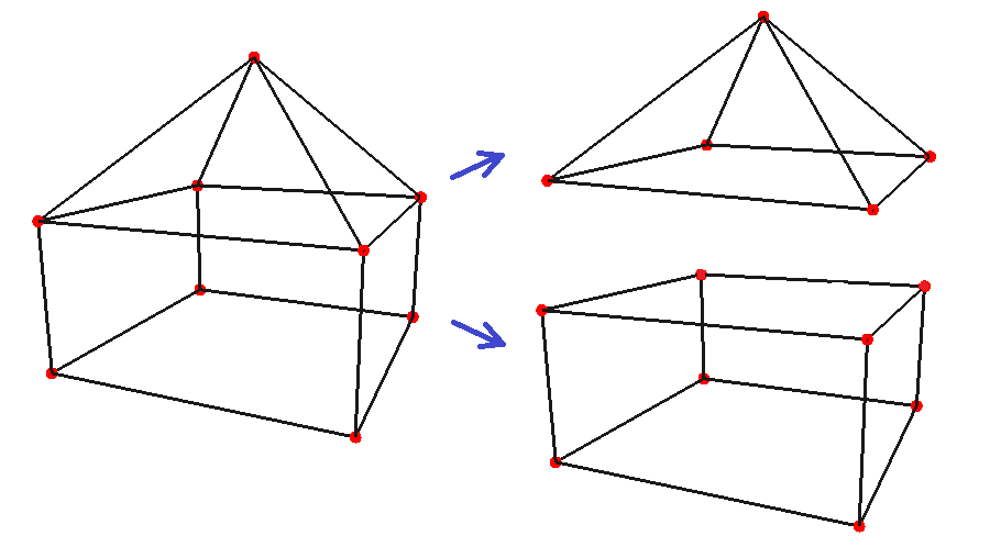
Figure 7: Generic #9 element and its separation into two different elements. -
•
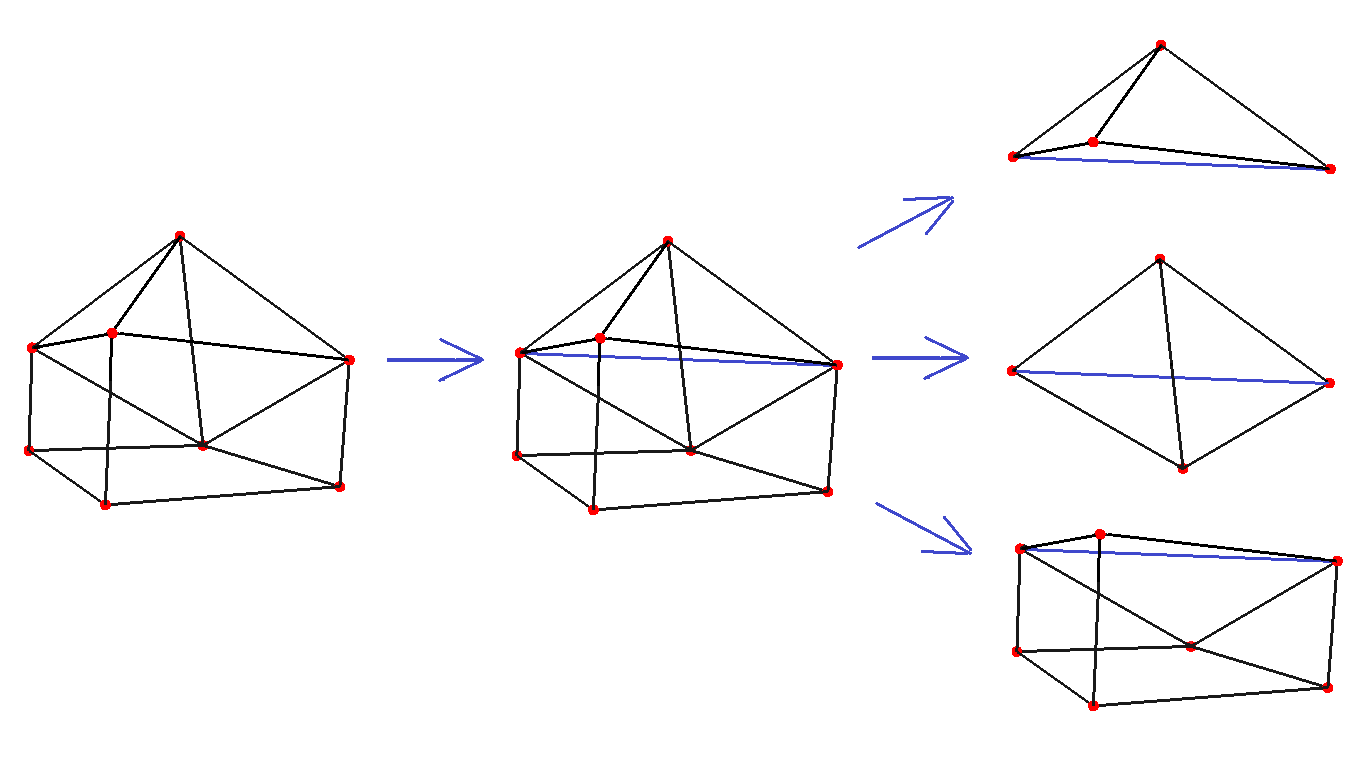
Minimizing the number of different co-spherical elements by adding internal edges and faces: This extends the second criterion by adding the condition that it is possible to add extra edges only if they are inside the new elements. The reason for only allowing internal edges is that adding external edges could change the partition of one of the rectangular faces of the original cuboid. Under this criterion, the elements that are separable are generic #3 (one inner edge produces two tetrahedra and one quadrilateral pyramid), generic #6 (one inner edge produces two tetrahedra and a tetrahedron complement) and generic #7 (two inner edges produce two tetrahedra, a quadrilateral pyramid and a deformed prism). An example of this type of separation is shown in Figure 8. The total number of co-spherical elements needed to tessellate the 4096 configurations is reduced to 13.
4.3 Evaluating the impact of each new element
In order to decide how important is to include a new element in the final element set, in this section we study how many times each co-spherical element appears in the tessellation of a 1-irregular cuboid. For this study, we have run our program for 1-irregular cuboids with three different aspect ratio: 1, 4, and .
-
•
Test case A. Aspect ratio equal to 1 (): The 1-irregular cube appears naturally on the standard octree and this method is used by most mesh generators based on octrees.
-
•
Test case B. Aspect ratio equal to 4 (): This represents a typical cuboid to model thin zones.
-
•
Test case C. Aspect ratio equal to (): It was shown in [9] that some 1-irregular cuboid within these proportions can be tessellated without problems for the finite volume method.
4.3.1 Running the test case A
Table 4.3.1 shows the frequency in which appear each one of the 24
co-spherical elements in the tessellations of 1-irregular cubes.
| Element | Freq. | Element | Freq. |
|---|---|---|---|
| Cuboid | 195 | Hexagonal Bipyramid | 36 |
| Tetrahedron | 18,450 | Triangular Biprism | 6 |
| Quadrilateral Pyramid | 11,718 | Generic #1 | 12 |
| Triangular Prism | 3,720 | Generic #2 | 96 |
| Tetrahedron Comp. | 992 | Generic #3 | 48 |
| Def. Prism | 396 | Generic #4 | 48 |
| Def. Tetrahedron Comp. | 144 | Generic #5 | 120 |
| Pentagonal Pyramid | 384 | Generic #6 | 24 |
| Hexagonal Pyramid | 56 | Generic #7 | 48 |
| Triangular Bipyramid | 240 | Generic #8 | 48 |
| Quadrilateral Bipyramid | 272 | Generic #9 | 6 |
| Pentagonal Bipyramid | 192 | Generic #10 | 8 |
| Total | 37,259 |
From Table 4.3.1, we observe that the most used elements correspond
to tetrahedra and quadrilateral pyramids (49.5% and 31.5% of the total elements, respectively). Moreover, the set of seven initial co-spherical elements represents 95.6% of the total. If the number of co-spherical elements is reduced to 16 by
adding internal faces, the element frequencies are distributed as shown in
Table 3. It can be observed that
the most used elements are again tetrahedra
and quadrilateral pyramids (49.5% and 32.7% of elements, respectively).
The set of seven initial co-spherical elements represents 96.9% of the total.
| Element | Freq. | Element | Freq. |
|---|---|---|---|
| Cuboid | 201 | Hexagonal Pyramid | 128 |
| Tetrahedron | 18,930 | Generic #1 | 12 |
| Quadrilateral Pyramid | 12,484 | Generic #2 | 96 |
| Triangular Prism | 3,900 | Generic #3 | 48 |
| Tetrahedron Comp. | 992 | Generic #4 | 48 |
| Def. Prism | 396 | Generic #6 | 24 |
| Def. Tetrahedron Comp. | 144 | Generic #7 | 48 |
| Pentagonal Pyramid | 768 | Generic #10 | 8 |
| Total | 38,227 |
Finally, when the number of different final co-spherical elements is reduced to 13, by
adding internal edges and faces, the element frequencies are shown in Table 4.
The most used elements correspond to tetrahedra and quadrilateral pyramids (49.8% and 32.7% of the total number of elements, respectively). The set of initial seven co-spherical elements represents 97.2% of the total.
| Element | Freq. | Element | Freq. |
|---|---|---|---|
| Cuboid | 201 | Pentagonal Pyramid | 768 |
| Tetrahedron | 19,170 | Hexagonal Pyramid | 128 |
| Quadrilateral Pyramid | 12,580 | Generic #1 | 12 |
| Triangular Prism | 3,900 | Generic #2 | 96 |
| Tetrahedron Comp. | 1,016 | Generic #4 | 48 |
| Def. Prism | 444 | Generic #10 | 8 |
| Def. Tetrahedron Comp. | 144 | ||
| Total | 38,515 |
4.3.2 Running the test Case B
When the aspect ratio of the cuboid is changed to 4, only 6 different co-spherical elements appear and their frequencies are shown in Table 5.
t
| Element | Freq. | Element | Freq. |
|---|---|---|---|
| Cuboid | 103 | Triangular Prism | 3,120 |
| Tetrahedron | 29,118 | Tetrahedron Comp. | 536 |
| Quadrilateral Pyramid | 12,620 | Def. Prism | 84 |
| Total | 45,581 |
From Table 5, we observe that tetrahedra and quadrilateral pyramids are the most used elements, comprising more than 90% of the total of the elements (63.9% of tetrahedra and 27.7% quadrilateral pyramids). Note that these elements can not be divided into simpler ones without adding diagonals on its quadrilateral faces.
4.3.3 Running the test Case C
When the aspect ratio is equal to , only
10 different final co-spherical elements appear whose frequencies are distributed as follows:
| Element | Freq. | Element | Freq. |
|---|---|---|---|
| Cuboid | 199 | Def. Prism | 284 |
| Tetrahedron | 25,252 | Triangular Bipyramid | 128 |
| Quadrilateral Pyramid | 12,300 | Quadrilateral Bipyramid | 52 |
| Triangular Prism | 3,780 | Generic #2 | 16 |
| Tetrahedron Comp. | 1,008 | Generic #5 | 16 |
| Total | 43,035 |
The most used elements correspond to tetrahedra and quadrilateral pyramids (58.7% and 28.6% of the total number of elements, respectively). Moreover, the set of initial seven co-spherical elements represents a 99.5% of the total. In this test case, the number of co-spherical elements can be
reduced from 10 to 7 by adding internal faces. The frequencies of
these seven elements are distributed as shown in Table 7.
| Element | Freq. | Element | Freq. |
|---|---|---|---|
| Cuboid | 199 | Tetrahedron Comp. | 1,008 |
| Tetrahedron | 25,508 | Def. Prism | 284 |
| Quadrilateral Pyramid | 12,420 | Generic #2 | 16 |
| Triangular Prism | 3,796 | ||
| Total | 43,231 |
Again, the most used elements are tetrahedra and quadrilateral pyramids (59.0% and 28.7% of elements, respectively). There are only 6 of the seven initial co-spherical elements, representing a 99.96% of the total. Notice that this set of 7 elements is not separable by adding internal edges or faces.
4.4 Tessellations and the finite volume method
We have also examined whether the generated tessellations meet the
requirements for their use in the context of the finite volume method.
The requirement is that the circumcenter of each final element is
contained within the initial 1-irregular cuboid.
This requirement is strong but it allows our mesh generator to find a proper tessellation of each 1-irregular cuboid locally.
The evaluation of each tessellation is performed on the same test cases discussed
in Section 4.2. The results are shown in Table 8.
We observe that the circumcenters of all elements are inside the initial
cuboid for all the configurations in the test cases A and C. This means
that all 1-irregular configurations could be properly tessellated if the
aspect ratio of the elements is less or equal to . If 1-irregular
cuboids has an aspect ratio equal to 4, only 132 1-irregular cuboids
fit the circumcenter requirement.
| Number of proper configurations | |
|---|---|
| Test Case A | |
| (Aspect ratio equal to 1) | 4096 |
| Test Case B | |
| (Aspect ratio equal to 4) | 132 |
| Test Case C | |
| (Aspect ratio equal to ) | 4096 |
5 Results: Intersection based approach
The number of 1-irregular configurations that can appear while refining cuboids by an intersection based approach is [7]. We consider that two 1-irregular configurations are different if the relative position of Steiner points located on parallel cuboid edges is not the same. In this section we describe the results obtained by applying the algorithm to all 1-irregular configurations of a cube that can be generated by inserting Steiner points only on the positions defined by multiples of 1/16 of the edge length. The impact of each co-spherical element was only obtained for the 1-irregular cube.
5.1 New co-spherical elements
Since the possible positions of Steiner points on a particular
edge are infinite, we only use a set of predetermined Steiner
point positions for each set of cuboid parallel edges
defined as follows:
-
•
The first vertex is always located at the midpoint of an edge.
-
•
If the -th point is located to the left of the previous points, its actual position is located at the midpoint of the segment defined by the left edge corner and the leftmost already assigned Steiner point. Similarly, if the -th point is located to the right, its actual position is determined by the midpoint of the segment defined by the rightmost assigned Steiner point and the right edge corner.
-
•
If the relative position of the -th point is between two Steiner points already allocated, its actual position is determined by the midpoint of the two Steiner points.
Under this approach we identified 14 new co-spherical elements in the tessellations of 1-irregular cubes. A description of each of them can be found in Table 9.
| Element | Vertices | Edges | Faces | Example |
|---|---|---|---|---|
| Generic #11 | 7 | 11 | 6 |
|
| Generic #12 | 7 | 11 | 6 |
|
| Generic #13 | 7 | 12 | 7 |
|
| Generic #14 | 7 | 13 | 8 |
|
| Generic #15 | 7 | 14 | 9 |
|
| Generic #16 | 8 | 12 | 6 |
|
| Generic #17 | 8 | 12 | 6 |
|
| Generic #18 | 8 | 13 | 7 |
|
| Generic #19 | 8 | 14 | 8 |
|
| Generic #20 | 8 | 15 | 9 |
|
| Generic #21 | 9 | 15 | 8 |
|
| Generic #22 | 9 | 15 | 8 |
|
| Generic #23 | 9 | 16 | 9 |
|
| Generic #24 | 9 | 16 | 9 |
|
5.2 Evaluating the impact of each co-spherical element
Table 5.2 shows a summary of the results obtained by generating the tessellations of all 1-irregular configurations
of a cube:
| Element | Freq. | Element | Freq. |
|---|---|---|---|
| Cuboid | 531 | Generic #6 | 58 |
| Tetrahedron | 39,590,100 | Generic #7 | 1,881 |
| Quadrilateral Pyramid | 5,200,926 | Generic #8 | 2,340 |
| Triangular Prism | 184,374 | Generic #9 | 6 |
| Tetrahedron Comp. | 11,220 | Generic #10 | 108 |
| Def. Prism | 84,200 | Generic #11 | 6,236 |
| Def. Tetrahedron Comp. | 14,701 | Generic #12 | 9,288 |
| Pentagonal Pyramid | 171,838 | Generic #13 | 3,972 |
| Hexagonal Pyramid | 7,353 | Generic #14 | 874 |
| Triangular Bipyramid | 625,447 | Generic #15 | 4,966 |
| Quadrilateral Bipyramid | 139,851 | Generic #16 | 146 |
| Pentagonal Bipyramid | 25,686 | Generic #17 | 204 |
| Hexagonal Bipyramid | 1,755 | Generic #18 | 1,361 |
| Biprism | 148 | Generic #19 | 4,033 |
| Generic #1 | 61,044 | Generic #20 | 197 |
| Generic #2 | 186,594 | Generic #21 | 42 |
| Generic #3 | 94,020 | Generic #22 | 214 |
| Generic #4 | 28,218 | Generic #23 | 4 |
| Generic #5 | 28,028 | Generic #24 | 6 |
| Total | 46,491,970 |
The trend observed in the bisection based approach is also observed here: the most used elements are tetrahedra and quadrilateral pyramids (85.15% and 11.19% of total elements respectively, corresponding to more than 96%). The initial set of seven elements represents a 96.98%, while the set of 24 elements found in configurations under the bisection based approach covers a 99.93%. Finally, the elements that appear exclusively under the intersection based approach represent only a 0.07% of the total.
6 Conclusions
We have identified 24 co-spherical elements while
tessellating 1-irregular cubes generated by a bisection based approach
and 38 co-spherical elements while tessellating 1-irregular cubes generated by an intersection
based approach. We have experimentally noticed that in the tessellation of
1-irregular cubes (aspect ratio equal to 1) more co-spherical elements
appear than in the tessellation of 1-irregular cuboids with larger aspect ratio. When we increase the
cuboid aspect ratio a subset of these co-spherical
elements is required and no new co-spherical element appears.
We have studied the tessellations of 1-irregular cuboids generated
by a bisection based approach with three
different aspect ratios: 1, , and 4. The results can be summarized
as follows:
-
•
All the tessellations for 1-irregular cubes and 1-irregular cuboids with aspect ratio from 1 to are adequate for the finite volume method. We would need to add 6 co-spherical elements to the initial final element set if we want that our mixed element mesh generator can tessellate the 1-irregular cuboids the first time the mesh is done 1-irregular.
-
•
The number of different co-spherical elements while tessellating 1-irregular cubes can be reduced from 24 to 16 by adding internal faces and to 13 by adding internal faces and edges. While tessellating 1-irregular cuboids with aspect ratio equal to , the required elements are reduced from 10 to 7 if we allow the insertion of internal faces. While tessellating 1-irregular cuboids with aspect ratio equal to 4 only 6 co-spherical elements are used.
We have also study the tessellations of 1-irregular cubes generated
by an intersection based approach and 14 additional co-spherical elements
appear. They represent less than 0.07% of the total, then it not useful to include them in the set of final elements. They would increase this set in 58% (24 to 38).
It is worth to point out that the proposed algorithm was only applied for tessellating 1-irregular
cuboids but it can also be used without any modification to tessellate
any 1-irregular convex configuration: 1-irregular prisms, pyramids or tetrahedra,
among others. Moreover, the algorithm can be used to generate Delaunay tessellations for any point set. It may be only required to recognize new co-spherical configurations. This means we could apply this algorithm to the points of
a larger part of the 1-irregular mixed element mesh and not only to the 1-irregular basic elements. The circumcenter requirement is only
really necessary for 1-irregular elements that are located at the boundary or at a material interface.
We have made the study under the assumption that all the 1-irregular
configurations
appear in the same rate, but this is for sure not true. While generating a mesh
based on modified octrees, there are some configurations that appear more
frequently than others. This fact could mean that some co-spherical elements
belonging to the tessellation of few 1-irregular cuboids, could have a
greater impact than the one we have computed if these few configurations appear very frequently
while generating a mesh. A complete study should consider also this case.
The study presented here is very useful for our mesh generator based
on modified octrees, but we think that it can also be useful for
other mesh generator based on octrees.
Acknowledgments
This work was supported by Fondecyt project 1120495.
References
- [1] R. E. Bank, D. J. Rose, and W. Fichtner, “Numerical methods for semiconductor device simulation,” IEEE Trans. on El. Dev., vol. ED-30, no. 9, pp. 1031–1041, 1983.
- [2] B. Delaunay, “Sur la sphère vide,” Bull. Acad. Sci. USSR(VII), pp. 793–800, 1934.
- [3] N. Hitschfeld, P. Conti, and W. Fichtner, “Mixed Elements Trees: A Generalization of Modified Octrees for the Generation of Meshes for the Simulation of Complex 3-D Semiconductor Devices,” IEEE Trans. on CAD/ICAS, vol. 12, pp. 1714–1725, November 1993.
- [4] N. Hitschfeld-Kahler, “Generation of 3D mixed element meshes using a flexible refinement approach,” Engineering with Computers, vol. 21, no. 2, pp. 101–114, 2005.
- [5] M. Yerry and M. Shephard, “Automatic Three-dimensional Mesh Generation by the Modified-Octree Technique,” International Journal of Numerical Methods in Engineering, vol. 20, pp. 1965–1990, 1984.
- [6] W. J. Schroeder and M. S. Shephard, “A Combined Octree/Delaunay Method for fully automatic 3-D Mesh Generation,” International Journal for Numerical Methods in Engineering, vol. 29, pp. 37–55, 1990.
- [7] N. Hitschfeld, G. Navarro, and R. Farías, “Tessellations of cuboids with steiner points,” in Proceedings of the 9th Annual International Meshing Roundtable, pp. 275–282, New Orleans, U.S.A., October 2-5, 2000.
- [8] C. B. Barber, D. P. Dobkin, and H. Huhdanpaa, “The quickhull algorithm for convex hulls,” ACM TRANSACTIONS ON MATHEMATICAL SOFTWARE, vol. 22, no. 4, pp. 469–483, 1996.
- [9] P. Conti, Grid Generation for Three-dimensional Device Simulation. PhD thesis, ETH Zürich, 1991. published by Hartung-Gorre Verlag, Konstanz, Germany.