Polariton boxes in a tunable fiber cavity
Cavity-polaritons in semiconductor photonic structures have emerged as a test bed for exploring non-equilibrium dynamics of quantum fluids in an integrated solid-state device setting Deng:RevModPhys10 . Several recent experiments demonstrated the potential of these systems for revealing quantum many-body physics in driven-dissipative systems Carusotto:RMP13 . So far, all experiments have relied on fully integrated devices with little to no flexibility for modification of device properties. Here, we present a novel approach for realizing confined cavity-polaritons, that enables in-situ tuning of the cavity length and thereby of the polariton energy and lifetime. Our setup is based on a versatile semi-integrated low-temperature fiber-cavity platform Colombe:Nature07 ; Hunger:NJP10 ; Muller:APL10 ; Sanchez:NJP13 , which allows us to demonstrate the formation of confined polaritons (or polariton boxes) with unprecedented quality factors. At high pump powers, we observe clear signatures of polariton lasing Imamoglu:PRA96 . In the strong-confinement limit, the fiber-cavity system could enable the observation of the polariton-blockade effect Verger:PRB06 .
Semiconductor microcavity polaritons are the elementary excitations resulting from the strong coupling of quantum-well (QW) excitons to photons confined in a high-Q microcavity Weisbuch:PRL92 . Due to their half-matter half-light character, cavity polaritons inherit the effective mass of the photons and at the same time interact with each other through the excitonic part of their wavefunction. In a 3D-confined polariton box, the average distance between two polaritons determines the strength of polariton-polariton interactions: The smaller the spatial extent of the polariton mode, the larger the interaction strength between polaritons. While such polariton boxes enable non-linear optical behavior, the single-photon non-linear regime has not been reached. In contrast, pronounced single-photon nonlinearities have been demonstrated with semiconductor self-assembled quantum dots strongly coupled to a cavity mode, where tight electronic confinement on nanometer length scales leads to a highly anharmonic quantum system Faraon:NatPhys08 ; Reinhard:NatPhot12 . For QW polaritons, confinement can be induced through post-growth engineering of the photonic and/or the excitonic part of the wavefunction. Exciton confinement has been achieved by controlled application of sample stress Nogoita:APL99 ; Balili:Science07 , naturally occurring defects Kasprzak:Nature06 , and recently by light-induced creation of spatially modulated excitonic reservoirs Wertz:NatPhys10 ; Amo:PRB10 ; Tosi:NatPhys12 . In particular the latter method provides very precise control over the potential landscape. However, the achievable confinement length scales are limited by the excitonic diffusion length of several. In addition, the presence of the large exciton reservoir and the additional off-resonant laser light might pose strong limitations for resonant probing techniques. Polariton confinement through its photonic part has been demonstrated by the use of mesa structures ElDaif:APL06 , micropillars Ferrier:PRL11 and photonic-crystal cavities Azzini:APL11 . However, these systems typically suffer from enhanced excitonic or photonic losses, once the spatial dimensions approach the -scale. In addition, their spectral tunability is limited.
Here, we demonstrate a new method for the implementation of tight polaritonic confinement which at the same time allows the experimenter to tune in-situ both energy and lifetime of the polaritons. Our semi-integrated cavity system consists of a concave dielectric distributed Bragg reflector (DBR) deposited at the end of an optical fiber tip, and a sample chip containing a semiconductor DBR and an optically active quantum-well layer grown on top (see Fig. 1a and Methods). The Fabry-Perot type cavity defines TEM Gaussian modes and thereby imprints the resulting polaritonic wavefunctions, yielding a lateral polariton confinement by all-optical means. Tuning the length of the cavity allows both for adjustment of the polariton lifetime and the precise tuning of the polariton energy at one and the same spot of the sample area. Using a single InGaAs quantum well, we observe an avoided level crossing of the polariton spectral lines as a function of cavity length, giving a Rabi splitting of 3.4 meV, consistent with previously reported values in literature. For a sample containing 9 quantum wells, we observe clear signatures of polariton lasing.
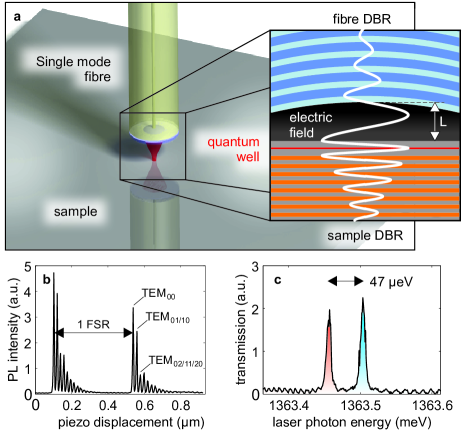
Figure 1a sketches the setup of our fiber-cavity system: The fiber is mounted a few micrometers above the surface of the semiconductor chip which consists of an AlAs/GaAs semiconductor DBR with the active InGaAs QW layers grown on top. A 3D-stack of attocube nanopositioner stages controls the position of the sample relative to the fixed fiber tip. The system is kept at K by immersing it in a liquid helium bath. For the experiments described here, we used four different samples (A, B, C, D) with 1, 4 or 9 QWs (for details see Methods). In order to probe the system, we first performed photoluminescence (PL) spectroscopy with nm excitation light. The fiber was used both for excitation and photon collection. Many of the intrinsic properties of the cavity can be inferred from PL spectra with the cavity mode far-detuned from the exciton resonance. Figure 1b shows the recorded PL-intensity at a fixed wavelength of 909.2 nm as a function of cavity length. In addition to two fundamental transverse electromagnetic TEM00 modes, which are separated by a free spectral range (FSR), the diagram shows a multitude of equally spaced higher-order transverse modes. All the cavity modes exhibit a polarization splitting that typically is significantly larger than the cavity linewidth Hunger:NJP10 (see Figure 1c). The quality factor of the cavity modes increases with the length of the gap between the fiber tip and the substrate. It exceeds values of at lengths of around . A more relevant figure of merit for a Fabry-Perot type cavity is the finesse which we determined from lifetime measurements for a cavity completely detuned from the exciton resonance. We found a finesse of up to which is presumably limited by the reflectivity of the on-chip semiconductor mirror. Another key parameter of our system is the waist size of the cavity modes. We measured values as small as Sanchez:NJP13 for a fiber mirror with a curvature radius of about . Based on Gaussian beam optics, we estimate a minimal achievable waist size of about at a wavelength of nm (assuming and ). This value for the confinement length scale of polaritons is at least comparable to or even better than currently feasible in mesas ElDaif:APL06 or micropillars Ferrier:PRL11 .
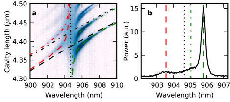
In order to demonstrate the formation of polariton branches, we approached the fiber tip close to the sample surface and performed PL spectroscopy for varying cavity length. The resulting data for sample D containing a single QW are shown in Figure 2a. The data exhibit an avoided-level crossing for all the cavity modes crossing the bare exciton line, clearly revealing the formation of upper-polariton (UP) and lower-polariton (LP) branches. Note that due to QW disorder, the LP resonance broadens and its amplitude reduces significantly as it approaches the bare exciton resonance (see Supplementary materials and Ref. Savona:JPCM07 ). All the higher-order transverse modes couple to the QW excitons with approximately the same strength as the fundamental TEM00 mode, which is theoretically expected due to the very weak dependence of the coupling strength on the in-plane exciton momentum. A fit to the first level crossings (green and red dashed and dashed-dotted lines) yields a Rabi splitting of meV. Figure 2b displays a cut through the Fig. 2a at the cavity length where the fundamental TEM00 mode is resonant with the exciton line. While both UP and LP branches are visible, the UP signal is much weaker and broader due to fast non-radiative decay. Note that we confirmed the formation of polariton branches by also probing their density of states directly with a resonant tunable laser (see Supplementary Material).
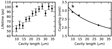
The key feature of our system is its tunability. It enables in-situ control of the cavity-exciton detuning, making the observation of an avoided-level crossing in one and the same spot on the sample possible. More importantly, when modifying the cavity length by several, the polariton lifetime can be significantly prolonged. Figure 3 illustrates this behavior for a sample containing 4 QWs (sample B). The lifetime data in Figure 3a were recorded in resonant-transmission spectroscopy using sub-picosecond laser pulses with a bandwith of nm centered at the QW resonance (see Supplementary Material). The results demonstrate ultra-long polariton lifetimes of up to ps for an overall cavity length of . For longer cavities, the measured lifetime saturates. This could be due to diffraction losses at the fiber mirror. The coupling strength as a function of length (Fig. 3b) was extracted from PL data similar to the ones of Figure 2a. The black line in Fig. 3b is a fit to the data based on the assumption that is proportional to the square root of the inverse effective cavity length , where is the weighted penetration depth of the cavity field into the DBRs. It is interesting to note that even though the physical length of our microcavity is much longer than the one of a monolithic semiconductor -cavity, for a length the coupling strength reaches a value almost as high as in a -cavity (see Supplementary Material).
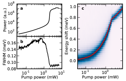
The long lifetimes reported here elevate our system into a new domain that should enable the study of equilibrated long-lived bosonic quantum fluids in an all-solid-state setting. In a first experiment highlighting this potential, we demonstrate polariton lasing in a 9-QW sample (C) consisting of three groups of three QWs, each positioned at adjacent anti-nodes of the intra-cavity field. Figure 4 displays the emitted PL intensity of the LP00 mode as a function of off-resonant excitation power for a very short cavity, where the fiber almost touches the sample. We choose a cavity-exciton detuning of corresponding to an exciton content of about 22% at low pump power. As is illustrated in Figure 4a), we observe a clear threshold behavior with a sharp non-linear increase in the emitted number of photons at around 2 mW of pump power. In addition, the linewidth of the LP00 mode starts to decrease and quickly drops below the spectrometer resolution (Figure 4b) while the energy shift versus pump power exhibits a kink. The latter behavior with the logarithmic blueshift above threshold can be attributed to polariton lasing Bajoni:PRL08 ; Roumpos:PRL10 . While the data taken here are restricted to the more photon-like part of the LP branch, a suitably designed sample with less exciton disorder, will allow the creation of truly equilibrated long-lived polariton gases having a high exciton content. Moreover, the tunability of our setup can be explored to study the physics of polariton lasing for a broad range of lifetimes and detunings. This should enable us to help understanding open questions regarding the transition from polariton to photon lasing Yamamguchi:PRL13 ; Ishida:arXiv13 .
In conclusion, we anticipate many exciting directions of research with the present fiber-cavity setup. A further improvement in the cavity-mode confinement would result in stronger interactions between single polaritons. Assuming a typical polariton-polariton interaction strength reported in the literature Amo:NatPhys09 , the regime of polariton blockade would be within reach Verger:PRB06 . In addition, the highly-tunable fiber-cavity system lends itself to the observation of the Feshbach-blockade effect proposed in Ref. Carusotto:EPL10 . More generally, our system opens up new horizons for the study of strongly correlated states in polariton fluids Carusotto:PRL09 , including fractional quantum Hall states of light Ucucalilar:PRL12 . On a more practical note, our semi-integrated platform combined with electrical injection of carriers Schneider:Nature13 could serve either as a fiber-coupled tunable low-threshold polariton laser or a quantum light source in the regime of polariton blockade.
This work is supported by NCCR Quantum Science and Technology (QSIT), research instrument of the Swiss National Science Foundation (SNSF), and an ERC Advanced Investigator Grant (A.I.). T.V. acknowledges support through the Center of Excellence for Engineered Quantum Systems, research instrument of the Australian Research Council (ARC). The authors thank Iacopo Carusotto and Vincenzo Savona for helpful discussions. The authors declare that they have no competing financial interests. Correspondence and requests for materials should be addressed to J.E. and T.V. (E-mail: esteve@lkb.ens.fr, thomas.volz@mq.edu.au)
Methods
Fiber and Samples
Key element of our new microcavity setup (displayed in Figure 1a) is the fiber mirror. In a first step, a concave mirror substrate in the form of an indent is fabricated by ablating and surface-melting the tip of an optical fiber using a CO2-laser. In a subsequent step, the fiber tip is coated with a dielectric mirror Colombe:Nature07 ; Hunger:NJP10 ; Sanchez:NJP13 (ATFilms, Boulder, Colorado). In the experiments, we mostly used single mode fibers. Multimode fibers do not allow for resonant reflection measurements but are equally suited for PL measurements. In Figure 1b, a multi-mode fiber was used - in this case more higher-order cavity modes couple to the fiber and are therefore visible in the PL spectrum.
The sample mirror consists of several pairs of AlAs/GaAs quarter-wave layers grown on a GaAs substrate by molecular beam epitaxy. The InGaAs quantum wells were grown on top and sandwiched between two GaAs spacer layers optimized for maximum coupling of QW excitons to the cavity modes. For the experiments described in this work, we used the following samples
| Sample | # QWs | In content [%] | QW thickness [nm] | # DBR pairs |
|---|---|---|---|---|
| A | 1 | 8 | 10 | 30 |
| B | 4 | 8 | 11 | 28 |
| C | 9 | 8 | 11 | 28 |
| D | 1 | 8 | 11 | 28 |
.1 Polariton lifetime measurements
For measuring polariton lifetimes, we excited the cavity through the fiber using a pulsed white-light source and a band-pass filter, resulting in a continuous spectrum of about bandwidth. The transmitted light of a TEM00 LP mode was guided out of the cryostat in a free-space configuration and sent to a spectrometer for analysis. We then sent the light to an avalanche photodiode (APD) in the Geiger mode and measured the ring-down time of the polariton emission (see Supplementary Material).
References
- (1) Deng, H., Haug H. & Yamamoto Y. Exciton-polariton Bose-Einstein condensation. Rev. Mod. Phys. 82, 1489-1537 (2010).
- (2) Carusotto, I. & Ciuti, C. Quantum fluids of light. Rev. Mod. Phys. 85, 299 (2013).
- (3) Colombe Y. et al. Strong atom-field coupling for Bose-Einstein condensates in an optical cavity on a chip. Nature 450, 272 (2007).
- (4) Hunger, D. et al. A fiber Fabry-Perot cavity with high finesse. New J. Phys. 12, 065038 (2010).
- (5) Muller, A., Flagg E. B., Lawall J. R. & Solomon G. S. Ultrahigh finesse, low-mode-volume Fabry-Perot microcavity. Opt. Lett. 35, 2293-2295 (2010).
- (6) Miguel-Sánchez, J. et al. Cavity quantum electrodynamics with charge-controlled quantum dots coupled to a fiber Fabry–Perot cavity. New J. Phys. 15, 045002 (2013).
- (7) Imamoglu, A. et al. Nonequilibrium condensates and lasers without inversion: Exciton-polariton lasers. Phys. Rev. A 53, 4250-4253 (1996).
- (8) Verger, A., Ciuti C. & I. Carusotto Polariton quantum blockade in a photonic dot. Phys. Rev. B 73, 193306 (2006).
- (9) Weisbuch, C., Nishioka M., Ishikawa A. & Arakawa Y. Observation of the coupled exciton-photon mode splitting in a semiconductor quantum microcavity. Phys. Rev. Lett. 69, 3314 (1992).
- (10) Faraon, A. et al. Coherent generation of non-classical light on a chip via photon-induced tunnelling and blockade. Nature Phys. 4, 859-863 (2008)
- (11) Reinhard, A. et al. Strongly correlated photons on a chip. Nature Photon. 6, 93-96 (2012)
- (12) Balili, R. et al. Bose-Einstein condensation of microcavity polaritons in a trap. Science 316, 1007-1010 (2007).
- (13) Nogoita, V. et al. Stretching quantum wells: A method for trapping free carriers in GaAs heterostructures. Appl. Phys. Lett. 75, 2059 (1999).
- (14) Kasprzak, J. et al. Bose-Einstein condensation of exciton polaritons. Nature 443, 409-414 (2006).
- (15) Wertz, E. et. al. Spontaneous formation and optical manipulation of extended polariton condensates. Nature Phys. 6, 860-864 (2010).
- (16) Amo, A. et. al. Light engineering of the polariton landscape in semiconductor microcavities. Phys. Rev. B 82, 081301 (2010).
- (17) Tosi, G. et al. Sculpting oscillators with light within a nonlinear quantum fluid. Nature Phys. 8, 190-194 (2012).
- (18) El Daïf, O. et al. Polariton quantum boxes in semiconductor microcavities. Appl. Phys. Lett. 88, 061105 (2006).
- (19) Ferrier, L. et al. Interactions in confined polariton condensates. Phys. Rev. Lett. 106, 126401 (2011).
- (20) Azzini, S. et al. Ultra-low threshold polariton lasing in photonic crystal cavities. Appl. Phys. Lett. 99, 111106 (2011).
- (21) Savona, V. Effect of interface disorder on quantum well excitons and microcavity polaritons. J. Phys.: Condens. Matter 19, 295208 (2007).
- (22) Bajoni, D. et al. Polariton Laser Using Single Micropillar GaAs-GaAlAs Semiconductor Cavities. Phys. Rev. Lett. 100, 047401 (2008).
- (23) Roumpos, G. et al. Gain-induced trapping of microcavity exciton polariton condensates Phys. Rev. Lett. 104, 126403 (2010).
- (24) Yamaguchi, M. et al. Second Thresholds in BEC-BCS-Laser crossover of exciton-polariton systems. Phys. Rev. Lett. 111, 026404(2013).
- (25) Ishida, N. et al. Photoluminescence of high-density exciton-polariton condensates. ArXiv:1311.1662v1(2013).
- (26) Amo, A. et al. Superfluidity of polaritons in semiconductor microcavities. Nature Physics 5, 805-810(2009).
- (27) Carusotto, I. , Volz, T. , & Imamoglu A. Feshbach blockade: single-photon nonlinear optics using resonantly enhanced cavity-polariton scattering from biexciton states. Europhysics Letters 90, 37001(2010).
- (28) Carusotto, I. et al. Fermionized Photons in an Array of Driven Dissipative Nonlinear Cavities. Phys. Rev. Lett. 103, 033601 (2009).
- (29) Ucucalılar, R. O. & Carusotto, I. Fractional Quantum Hall States of Photons in an Array of Dissipative Coupled Cavities. Phys. Rev. Lett. 108, 206809 (2012).
- (30) Schneider, C. et al. An Electrically pumped polariton laser. Nature 497, 348 352 (2013).
I Supplementary Material
I.1 Role of exciton disorder
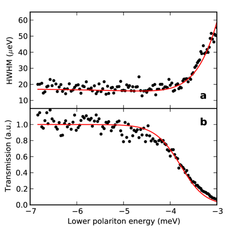
From the PL spectra shown in Figure 2, we observe that the LP mode broadens when the cavity mode approaches the QW-exciton resonance. We attribute this effect to the presence of structural disorder in the QW that is mostly due to alloy-fluctuations associated with the high In content. Prior to inserting the sample into the fiber cavity, we measured the QW-exciton free-luminescence spectrum and observed a full-width at half-maximum of . To confirm that this inhomogeneous broadening of the exciton line is responsible for the observed PL spectra, we performed resonant-excitation measurements for which quantitative predictions can be made more easily. The transmission spectrum of the cavity mode is measured using a photodiode glued to the backside of the sample, while tuning the frequency of an excitation laser coupled to the fiber. We repeated the experiment for different cavity lengths and fitted each lower-polariton resonance to a Lorentzian. The curves in Figure S1 show the dependence of the resonance widths and amplitudes as a function of the peak central energy. In addition, we calculated the expected transmission spectra using the model of an inhomogeneously broadened ensemble of harmonic oscillators coupled to a cavity mode Houdre:1996iv ; Diniz:2011dp ; Kurucz:2011gu . This model describes excitons moving in a random potential, neglecting the kinetic energy of the exciton Whittaker:1998bb .
The three parameters entering the model are the light-matter coupling constant that we extracted from the Rabi splitting in PL measurements, the cavity linewidth that we extracted from the cavity transmission spectrum far detuned from the QW, and the rms width of the Gaussian probability distribution describing the inhomogeneous ensemble of oscillators. A fit to the data leads to , which is compatible with the observed free PL linewidth. The model (solid lines in Figure S1) quantitatively reproduces the increase of the LP linewidth together with the decrease of the transmitted power when the cavity mode is brought into resonance with the QW. The small ratio results in disorder playing an important role in the system dynamics. Increasing this ratio to a value larger than 4, would render the presence of QW disorder almost negligible Houdre:1996iv ; Diniz:2011dp ; Kurucz:2011gu .
I.2 Quantum well–cavity coupling
The coupling strength of a single QW to a micro-cavity depends on two parameters: the oscillator strength per surface unit of the QW that we denote by and the effective length that characterizes the confinement of the cavity mode in the direction perpendicular to the QW layer. The expression of is Panzarini:1999dh
| (1) |
where is the vacuum permittivity, the charge quantum and the electron mass. For a 2D planar micro-cavity, the effective length can be defined as
| (2) |
where () gives the dependence of the refractive index (electric field) along the cavity axis. denotes the position of the QW. For a microcavity where the mode is also confined in the transverse directions, such as our fiber Fabry-Perot (FFP) cavity, equation (2) still holds if the paraxial approximation can be used to describe the cavity mode. In this case is the longitudinal dependence of the electric field, which is the same as for a plane wave. Here, we also assume that the transverse mode confinement is much larger than the exciton Bohr radius.
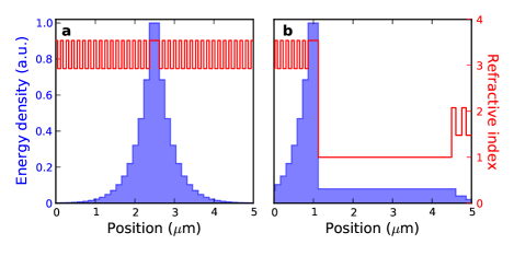
In a typical 2D planar GaAs microcavity, the QW is grown in the middle of a GaAs layer with optical thickness . This so-called -cavity is surrounded by two AlAs/GaAs DBRs (see figure S2). The electric field penetrates each DBR on a length scale given by Panzarini:1999dh
| (3) |
where we used , and nm. The effective length is the sum of the optical length () of the spacer layer plus the penetration length of each mirror, multiplied by the square of the refractive index of the spacer layer, here GaAs:
| (4) |
Inserting numerical values gives an effective length of . Together with a typical oscillator strength of Panzarini:1999dh , this leads to a value of meV.
In the case of our FFP cavity, the bottom half of the cavity has the same structure as the -cavity described above. The QW is at the center of a thick GaAs layer grown on top of an AlAs/GaAs DBR. The top DBR is made of dielectric materials (Ta2O5/SiO2) and is separated from the sample surface by a gap (vacuum) of length (see Figure S2). The penetration length in the top mirror is Panzarini:1999dh
| (5) |
where we use , . This expression is different from (3), because the dielectric DBR starts with a high index layer (Ta2O5), whereas the AlAs/GaAs mirror starts with a low index layer (AlAs). Taking into account that the lower DBR mirror is surrounded by GaAs and the top one by vacuum, we obtain the following expression for the effective length of the FFP cavity
| (6) |
which gives the approximate expression
| (7) |
Despite its much longer physical length, a FFP cavity with a gap of 3.5 m therefore has the same effective length than a monolithic GaAs -cavity.
I.3 Measurement of polariton lifetimes
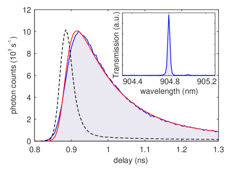
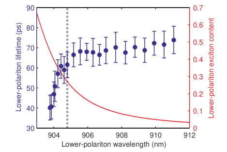
In order to measure polariton lifetimes, we excited the cavity through the fiber using a pulsed (sub-picosecond at a rate of ) white-light source and a band-pass filter, resulting in a continuous spectrum of about bandwidth. The transmitted light was guided out of the cryostat in a free-space configuration and sent to a spectrometer. We made sure that only the TEM00 LP line appeared in the transmitted spectrum. We then sent the light to an avalanche photodiode (APD) in the Geiger mode and measured the ring-down time of the polariton emission. Figure S3 shows the time-dependent transmission recorded on the four-QW sample at a cavity length of . Because of the finite time resolution of the APD (40 ps), we fit the ring-down signal (blue trace) by an exponential decay convolved with the APD response (red trace). The fitted decay time of the exponential decay corresponds to the polariton lifetime. In addition to LP lifetimes as a function of the cavity length (see Figure 3 in the main text), we investigated the lifetime dependence as a function of cavity-exciton detuning at a cavity length of . At this length, the Rabi splitting is . The results are shown in Figure S4. Due to exciton disorder, the lifetime decreases significantly when the LP wavelength becomes smaller than , in agreement with the line broadening discussed in the previous section. At , the lifetime is still as high as corresponding to an exciton content of about . We found this wavelength to be a good compromise between low disorder scattering and high exciton content. At this wavelength, the lifetime data of Figure 3 (main text) were recorded.
References
- (1) Houdré, R., Stanley, R. P. & Ilegems, M. Vacuum-field Rabi splitting in the presence of inhomogeneous broadening: Resolution of a homogeneous linewidth in an inhomogeneously broadened system. Phys. Rev. A 53, 2711 (1996).
- (2) Diniz, I. et al. Strongly coupling a cavity to inhomogeneous ensembles of emitters: Potential for long-lived solid-state quantum memories. Phys. Rev. A 84, 063810 (2011).
- (3) Kurucz, Z., Wesenberg, J. H. & Mølmer K. Spectroscopic properties of inhomogeneously broadened spin ensembles in a cavity. Phys. Rev. A 83, 053852 (2011).
- (4) Whittaker, D. M. What Determines Inhomogeneous Linewidths in Semiconductor Microcavities? Phys. Rev. Lett. 80, 4791 (1998).
- (5) Panzarini, G. et al. Exciton-light coupling in single and coupled semiconductor microcavities: Polariton dispersion and polarization splitting. Phys. Rev. B 59, 5082 (1999).