Current-driven flow instabilities in large-scale liquid metal batteries, and how to tame them
Abstract
The use of liquid metal batteries is considered as one promising option for electric grid stabilisation. While large versions of such batteries are preferred in view of the economies of scale, they are susceptible to various magnetohydrodynamic instabilities which imply a risk of short-circuiting the battery due to the triggered fluid flow. Here we focus on the current driven Tayler instability and give critical electrical currents for its onset as well as numerical estimates for the appearing flow structures and speeds. Scaling laws for different materials, battery sizes and geometries are found. We further discuss and compare various means for preventing the instability.
keywords:
liquid metal batteries , magnetohydrodynamics , flow instabilities , Tayler instability1 Introduction
With the large-scale deployment of renewable energy sources, massive and cheap electricity storage becomes indispensable since the major part of renewable electricity generation (solar, wind) is inherently fluctuating. Storage is thus essential to balance supply and demand and to stabilize the power grid.
Given that the potential for pumped storage hydropower is largely exhausted, electrolytically generated hydrogen, partly processed to synthesized hydrocarbons, seems to be the only viable option for long-term large-scale storage on the TWh scale. However, the total efficiency of the conversion chain is relatively low due to the multitude of process steps involved. Electrochemical energy storage (EES) shows generally higher efficiencies, but needs improvements towards larger capacities at significantly lower costs [1]. If these demands can be met, EES will be an attractive candidate for short-term and mid-term stationary electricity storage.
Liquid metal batteries (LMBs) are currently discussed as a means to provide economic grid-scale energy storage [2]. Typically, an LMB consists of a liquid alkaline metal layered atop a molten salt which itself floats on a molten metal or half metal. On discharge, the alkaline metal of the anode is oxidized and cations enter the fused salt which is often an eutectic composed of alkali halides. At the electrolyte/cathode interface, alkaline ions leave the electrolyte, are reduced and alloy with the cathodic metal. For this setup to work, the alkaline metal needs to be lighter than the metal forming the cathode, and the molten salt’s density must be in between those of both metals. A battery with a fully liquid active interior has a number of advantages: The battery is self-assembling due to stable density stratification. Liquid-liquid interface processes possess fast kinetics, thereby allowing for fast charging and discharging and high current densities (about 4 - 100 kA m-2). Structureless electrodes are insusceptible to aging which allows for potentially unlimited cyclability. Scale-up on the cell level is facilitated by the simple cell construction. Drawbacks include the elevated operation temperature and the relatively low cell voltage (typically below 1 V).
LMBs, or molten salt batteries [3], were intensively investigated in the 1960s mainly as part of energy conversion systems, i.e., thermally regenerative electrochemical systems (TRES). Interestingly, already at that time the use of LMBs for off-peak energy storage received interest as well as funding [4]. Among the systems investigated early were Na-Sn [5, 6] and K-Hg [7] because they can be easily separated by distillation. In the quest for higher cell voltages and current densities, among others, Na-Bi, Li-Te, and Li-Se cells were built, abstaining from thermal separability for the two latter systems. Progress in the field has been reviewed several times in the 1960s and early 1970s: Crouthamel and Recht [8] edited a special volume of Advances in Chemistry in 1967 dedicated to “regenerative EMF cells”. The large body of research performed at Argonne National Laboratory was discussed in detail by Cairns et al. [9] and described in a more compressed version by Cairns and Shimotake [10]. Swinkels’ [3] discussion had a slightly broader scope. A very recent account is due to Kim et al. [11] who not only review the previous achievements, but report on the ongoing research at the Massachusetts Institute of Technology (MIT) as well. The focus of the MIT activities is on the deployment of LMBs for large-scale stationary energy storage [2]. Consequently, emphasis is now on different practical and economical aspects as the utilization of abundant and cheap active materials [12].
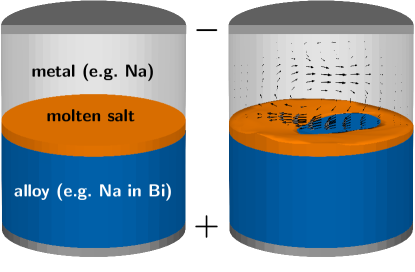
Besides the chemistry of different material combinations, and the related corrosion problems, there are further aspects of LMBs which should not be overlooked. For traditional battery systems (apart from lead-acid and redox flow batteries) fluid dynamics does not play a significant role. This is different for LMBs due to their completely liquid interior. On the one hand, mass transfer in the electrolyte and the cathodic compartment can be facilitated by liquid motion. On the other hand, the density stratification – appearing stable at first glance – might be disturbed by flow instabilities (see Fig. 1). Here we will focus on a special magneto-hydrodynamic phenomenon. After a few short remarks on interface instabilities in current carrying systems, we will proceed to the current-driven, kink-type Tayler instability, which is the main subject of the paper. It should be noticed that the significance of hydrodynamically stable interfaces for the operation of LMBs was recognized early, see, e.g., Cairns et al. [9] and Swinkels [3].
Interface instabilities are well known phenomena in Hall-Héroult, i.e., aluminum reduction cells (ARCs) [13, 14, 15, 16, 17]. These instabilities result from the interaction of the ionic current with a background magnetic field generated by the current supply lines. As a consequence, waves with a length comparable to the cell width develop and culminate in a sloshing motion of the aluminum. Amplitudes may become high enough for the aluminum to contact the graphite anodes, effectively short-circuiting the cell and terminating the reduction process. To keep the long-wave instabilities at bay, the cell current has to be kept below a critical value and the cryolite layer should not be thinner than about 4.5 cm. These requirements lead to a total cell voltage of about 4.5 V. 2 V of those, i.e., around 40% of the cell voltage are spent on overcoming the ohmic resistance of the electrolyte layer, the corresponding power is converted to heat [15]. Since expenses for electricity are a major part of the overall costs of aluminum production, a reduction of the electrolyte thickness even by a few millimeters only would result in huge savings, but is impeded by the long-wave interface instabilities described above.
ARCs have two liquid layers sandwiched between the carbon anode on top and the current collector on the bottom. In contrast, LMBs are three layer systems. Presently, only little is known about current driven interface instabilities in such settings. Sneyd [18] predicts theoretically that additional short wave instabilities may arise in the case of the two neighboring liquid-liquid interfaces. To the authors’ best knowledge, no experimental observations of current driven instabilities in three layer systems with closely spaced interfaces have been reported to date. Hoopes cells, i.e., three-layer cells used for the electrolytic refining of aluminum, apparently do not suffer from such instabilities. The electrolyte layer of these cells is quite massive with about 8 to 10 cm thickness [19, 20]. Thus, a strong interaction of both interfaces is relatively unlikely. However, violent swirling motions driven by non-uniform electric and magnetic fields emerging from the cathodic current collectors were observed already quite early [21]. These flows occurred, if the cathode metal thickness was chosen too small. As a result, spotty contacts of anode and cathode layers could happen.
Coming back to LMBs, the maximum thickness of the electrolyte layer is limited by the requirement that the voltage loss in the electrolyte must not exceed the available open circuit voltage (OCV). Indeed, a meaningful design requires the voltage losses to be much smaller than the OCV. For the most relevant combinations of metals and salts, this means the electrolyte’s thickness should not exceed a few millimeters. Under those conditions, a careful consideration of the stability of the interfaces becomes imperative.
Exploiting the economies of scale is the usual route towards economic devices. Since current densities are large, cell scale-up (up to a few cubic meters [22]) will result in considerable total cell currents. These large currents can trigger the so-called Tayler instability (TI), as has been shown in a recent liquid metal experiment by Seilmayer et al. [23]. The TI is a kink type instability very similar to that occurring in the z-pinch of plasma physics. TI manifests itself in one or, depending on the cell’s aspect ratio, more vortices rotating around an axis normal to that of the cell. Weber et al. [24] developed an integro-differential equation solver (in the sense of Meir et al. [25]) capable of reproducing the experimental findings in minute detail. Building upon these results, we will use the numerical toolbox to discuss the consequences of the TI for the construction of larger LMB cells. Starting with a discussion of the proper dimensionless number describing the TI’s onset in different materials, we will proceed to the influence of the cell’s aspect ratio on the TI, and to various possible countermeasures. The first of these measures consists in modifying the cell interior with a central bore. Second, we will feed a current through a conductor placed in this central bore. Both methods were derived from stability theory by Stefani et al. [26] and are here numerically confirmed to be effective. Third, a stabilization method based on imposing an axial or horizontal magnetic field, which requires no modification of the cell’s interior, will be discussed. Obviously, such a method would be preferred over more invasive approaches. All three stabilization methods act by modifying the electromagnetic field in the cell.
Mechanical means of flow stabilization, like the use of baffles to break long-wave motions, are limited by the need to find materials capable of withstanding the aggressive environment [15]. Additionally, an immobilization of the electrolyte by using pastes or ceramic matrices results in considerably larger values of the internal cell resistance. A six-fold increase has been found by Heredy et al. [27], similar values can be deduced from Cairns and Shimotake [10].
Finally, we would like to reiterate that not every fluid motion is necessarily dangerous for LMBs. Quite in contrast, under certain circumstance it can even be beneficial, in particular in the cathodic compartment. There, mass transport limitations and associated problems like concentration polarization and local solidification at the alloy-electrode interface can be mitigated or avoided by agitation. Diffusion control in bimetallic cells was observed by several researchers [28, 27, 2, 11] as well as the formation of intermetallics [29, 12]. Equally early it was obvious that stirring would be a remedy [30, 29, 3]. Giving the high temperature environment, electromagnetic agitation constitutes an attractive means requiring no direct contact with the hot metal or construction material. Yet, even when considering the possible advantages of flow instabilities for LMBs, they have to be well understood in the first instance. This is the main goal of the present paper.
2 The Tayler Instability in liquid metal batteries
Typically, liquid metal batteries are assumed to have the shape of a cylinder or a cuboid. Their aspect ratio, i.e. the ratio of height to horizontal extension, depends on the envisioned storage capacity. Flat batteries have low capacities, but, as we will see below, are less vulnerable to the TI than taller batteries with higher capacity. While the economies of scale demand for liquid metal batteries with a large size in general, thermal insulation aspects make a point for choosing rather compact design with an aspect ratio close to one.
Postponing this aspect ratio issue to the next section, here we would like to start with characterizing the TI in a paradigmatic geometry. Focusing on its dependence on various material parameters of the liquids to be utilized, we consider four typical anode materials for which we will compute the critical currents, the growth rates, and the velocities in the saturated state of the TI. Note that, as a rule, cathode materials are less conductive and more dense, which makes them less susceptible to the TI than the anode materials, although this has to be verified for each particular material combination.
2.1 Growth rates and critical currents
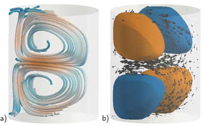
Fig. 2 illustrates both the flow structure (a) and the induced vertical magnetic field component (b) for an assumed liquid metal column with diameter mm and height mm, i.e. an aspect ratio of . For this particular aspect ratio the TI acquires the form of two vortices, the highest velocities appearing approximately at mid-height of the cell. The only slightly lower horizontal velocity at the bottom of the liquid anode column has to be considered with regard to its capability to shear off the thin electrolyte layer and hence to destroy the stable stratification of the three layer system.
For this geometry, and the four anode materials K, Li, Na, and Mg, Fig. 3 shows the dependence of the growth rate of the TI on the total current through the column. The growth rate of a linear instability is defined by the exponential increase of its typical perturbations, in our case of the perturbations of the velocity and the magnetic field. The critical current for either material, obtained by setting , is shown in the second column of Table 1. The third column indicates the corresponding Hartmann number, a dimensionless number often used in magnetohydrodynamics whose square measures the ratio of magnetic forces to viscous forces in a fluid. Here, the Hartmann number is defined as
| (1) |
where is the azimuthal magnetic field at the outer radius , is the electrical conductivity, the kinematic viscosity, and the density of the fluid. As can be seen in Eq. (1), the Hartmann number does not depend on the radius of the battery but only on the total current through the liquid

Evidently, we obtain the same critical Hartmann number of 29 for all the considered materials which means that is indeed the governing dimensionless number for the onset of the TI. We can further define a dimensionless growth rate of the TI by dividing the physical growth rate by the inverse of the typical viscous time scale . Fig. 4 shows then this dimensionless growth rate in dependence on . Not surprisingly, the curves for all four materials collapse into one single curve. This means, in turn, that for any concrete anode or cathode material we could work with the critical (which is 29 for the chosen aspect ratio) and derive from that the critical current.
| metal | A | Hacr |
|---|---|---|
| K | 1163 | 29 |
| Li | 1666 | 29 |
| Mg | 2488 | 29 |
| Na | 1183 | 29 |

2.2 Saturation level
A quite analogous procedure can be applied when determining the dependence of the saturated velocity on the total current. For each of the considered liquid metals, in Fig. 5 we plot the rms value of the velocity in dependence on the current. For the particular case of using K, and a current of 6 kA, this rms value reaches a value 5.5 mm s-1. The maximum speed at the bottom is approximately double that value, i.e. 1 cm s-1, which may already be considered a danger for the integrity of a thin electrolyte layer below it.
Again, these four curves can be collapsed into a single one (see Fig. 6) when going over from the physical quantities to the appropriate dimensionless parameters. On the abscissa, this is again , while the appropriate dimensionless number for measuring the mean velocity is the Reynolds number, defined by
| (2) |
On closer inspection, and based on previous computations [31], it turns out that for large currents grows quadratically with , so that for a given electrolyte layer thickness there is definitely a current at which the TI would destroy the stable stratification.


To summarize this section, we have seen that the TI is completely governed by the Hartmann number, which determines both the non-dimensionalized growth rate in the exponential growth phase as well as the Reynolds number of the saturated flow. For any concrete material and size of the liquid column, Figs. 4 and 6 would allow to determine the physical growth rates and the final velocity scale by using the definitions (1) and (2), respectively.
3 Taming the Tayler Instability
Having seen that for large charging or discharging currents the TI may indeed pose a problem for the stability of the liquid three-layer system, in this section we will discuss various methods how to tame it. The first idea that comes to mind here is the insertion of some non-conducting, e.g., ceramic) blades into the battery for preventing or at least damping the TI triggered flow. As simple as this may sound, it is not without problems, a serious one being connected with the fluctuating height of the layers during charging and discharging which could result in thin metal layers adhering to the blades that would lead to a short circuit. A similar method could rely on using a swimming ”carpet” below or above the electrolyte in order to stabilize the latter. Just for completeness, we also note the somewhat fancy possibility to tame the TI by setting the total battery into rotation [31].
While not excluding any viable solution based on inserting blades, or felts, into the battery, in the following we will exclusively focus on those solutions that maintain the advantageous simplicity of a compact fluid inventory that is not separated into more different segments than necessary. We will indeed see that the intrinsic dependence of the TI on geometric factors, on one side, and on external magnetic fields, on the other side, allows for quite simple methods to suppress it. Accordingly, we will exploit the effect that the critical current increases with decreasing height of the liquid metal layers, but also with the radius of an supposed central bore. Second, we will see that a central return current through such a bore would completely prevent the TI from occurring, and that the same stabilization effect can be achieved by applying a vertical or horizontal magnetic field.
3.1 Dependence on the aspect ratio
As many other flow instabilities, the TI is characterized by an optimal axial wavelength for which its growth rate and its saturated velocity scale become maximal. This means, in turn, that if the height of the liquid column falls below the half of this optimal wavelength, the instability is significantly damped or even suppressed. For that reason, flat batteries are much less vulnerable to the TI. Yet, if a high storage capacity per cell is desired, the liquid metal columns must be tall enough. Assuming a current density of 10 kA m-2, a 10 mm thick sodium layer is transferred per hour from the anodic to the cathodic compartment. This quickly adds up to a meter, if storage capacities of a few days are demanded.
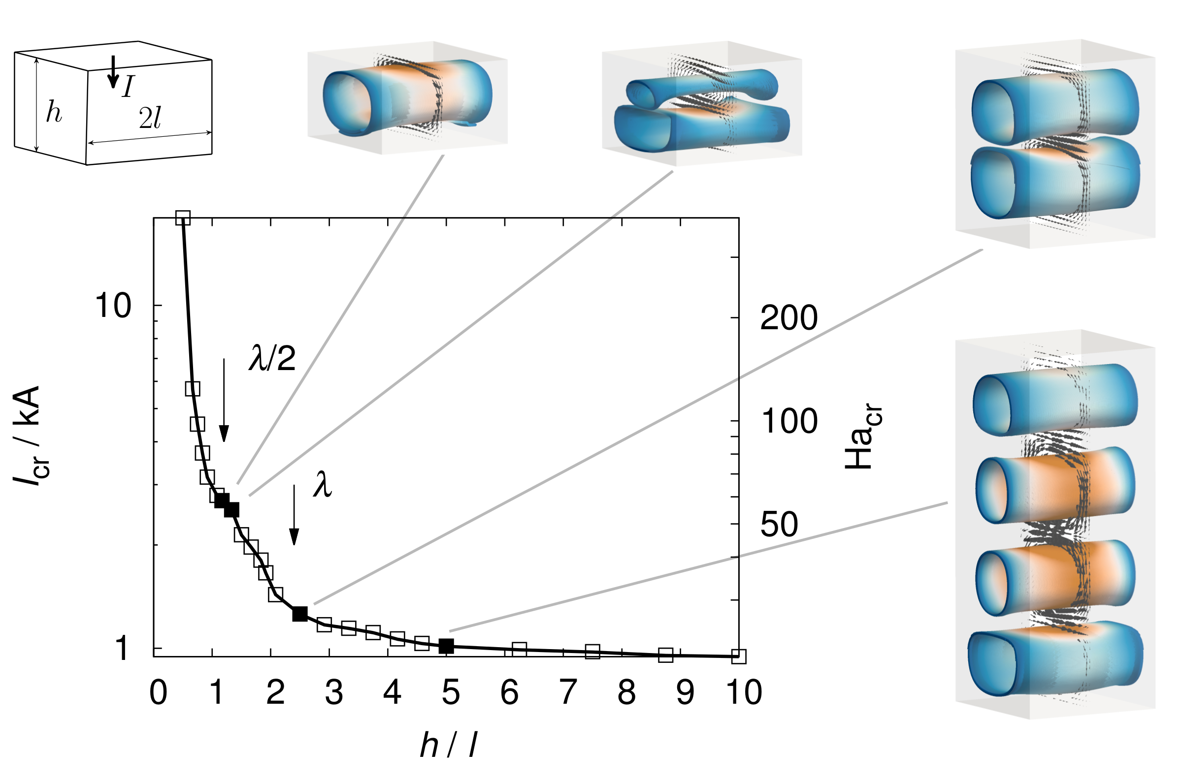
Reiterating the results of Weber et al. [24], in Fig. 7 we illustrate the dependence of the critical Hartmann number on the aspect ratio of a cuboid with height and width . Starting at high values of , we first observe a very moderate increase of which becomes significantly steeper after having passed a sort of plateau at . This is the aspect ratio where just one wavelength of the TI fits into the column. Interestingly, a second plateau forms approximately at , where just half a wavelength fits into the column. For even shallower columns, a very steep increase of can be observed. It should be noticed that this sensitive dependence may also lead to a transient behaviour of the TI when the height of the better conducting layer (i.e., in most cases the upper one) changes during the charging/discharging process.
3.2 A central bore in the battery
A simple trick to increase the critical current had already been devised in a recent paper [26]. Assuming a column of infinite length, it was shown that the mere existence of a central bore in the middle of the cylinder would increase the critical current. Even when taking into account the corresponding area reduction, the allowed total current through the remaining area is still higher than without this central bore.
Here, we concretize and confirm this behaviour for the more realistic case of a finite height cylindrical column. Again, we use the example of an electrode of liquid Na with an outer diameter of mm and a height of mm. The inner diameter is assumed variable. Increasing this diameter of the bore, the critical current for the onset of the TI increases more or less linearly. When the inner radius reaches about 40 % of the outer radius, the critical currents start to increase even steeper (Fig. 8). This bend of the curve is caused by a change in the flow structure of the TI. While the flow maintains its basic vortex structure for small bores, it acquires a more spiral shape for larger bores.
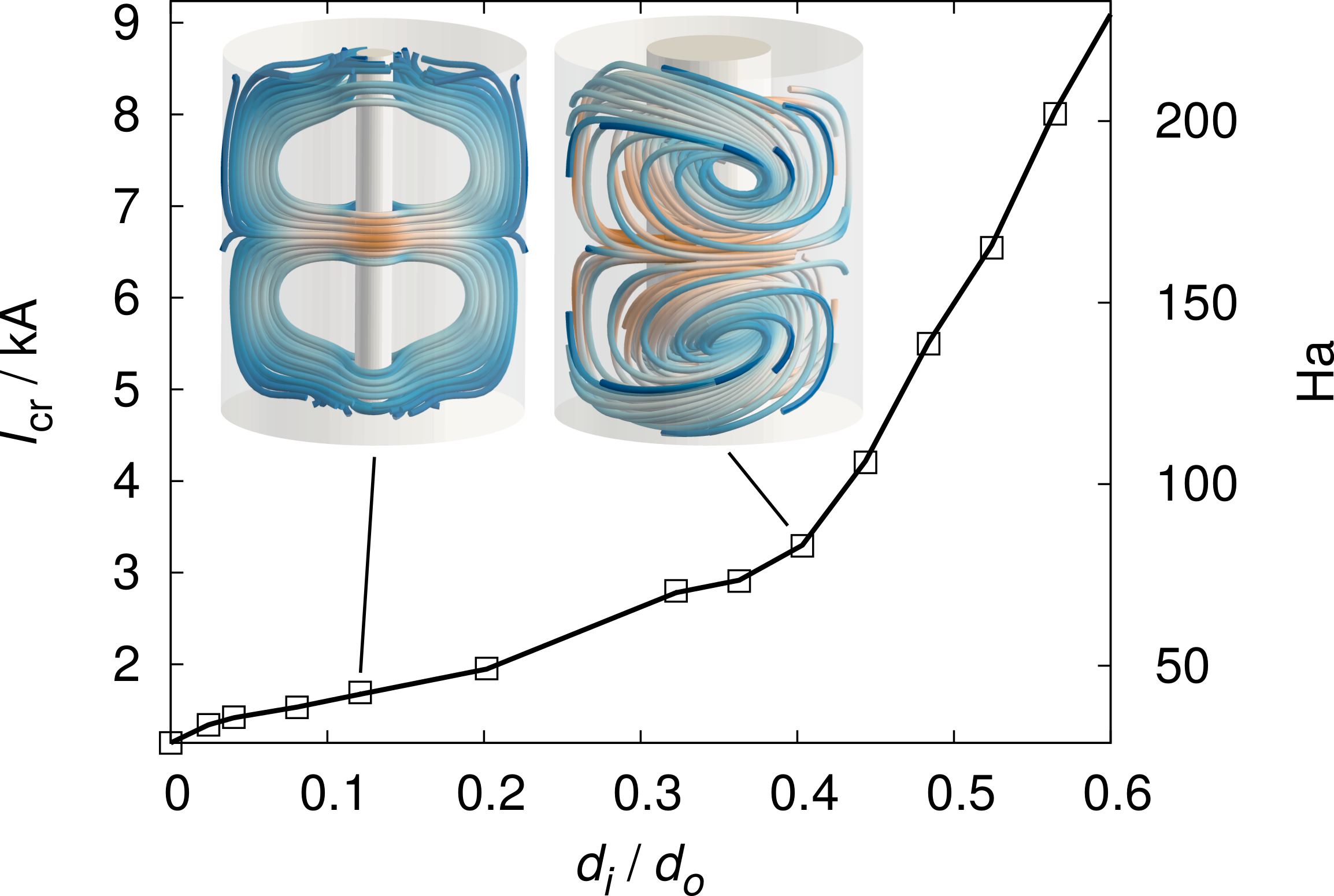
Fig. 9a illustrates a corresponding technical solution, with a central bore going through the total battery. It should be noticed, however, that the gain in terms of achievable critical current is typically only by some factor in the order of 2 – 10 or so. A more radical way of preventing the TI will be discussed in the following.
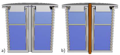
3.3 Returning the current
Imagine now that the central bore is equipped with a massive wire as indicated in Fig. 9b. For the idealized case of an infinite length cylinder, and assuming the fluid to be non-viscous and non-resistive, it had been shown that the TI can be completely suppressed by sending an appropriate current through this wire [26]. This additional current changes the radial dependence of the azimuthal magnetic field so that the ideal stability condition [32]
| (3) |
may be met. To fulfill this condition, one can either use a current in the same direction as the charging/discharging battery current , with an amplitude of , or in the opposite direction with an amplitude . Evidently, the second method needs less current and will therefore lead to less total losses. It is also more convenient from the technical point of view, since the charging/discharging current can be easily redirected (see Fig. 9b).
Here, we consider the more realistic case of a finite height column, and we take into account the real viscosity and resistivity of the fluid. We will see that the TI can already be suppressed by sending back only a part of the battery current. We use the same geometry as before, and fix the inner diameter to mm. We consider now a battery current of 4 to 10 kA, increase the return current step by step and measure the growth rate of the TI (Fig. 10). Evidently, for this realistic setting the TI disappears already for return currents smaller then .

This fact might be utilized, e.g., in a stack of connected batteries in order to minimize the voltage drops in the central wires.
3.4 Axial magnetic field
It has been known for a long time that current-driven instabilities can be re-stabilized by applying an axial magnetic field. In plasma physics, this effect goes under the notion Kruskal-Shafranov condition for the so-called safety parameter, which is basically a ratio of axial to azimuthal magnetic field. Related experiments have shown that the kink-type instabilities can indeed be switched off when a sufficiently strong axial magnetic field is applied [33].
In order to verify this effect for the battery case, we have again to take into account the finite height and the real viscosity and resistivity of the materials. For the sake of concreteness, we assume a geometry as indicated in Fig. 11, with a Helmholtz-like coil configuration to produce a rather homogeneous axial field in the battery. We will start with one single winding in each part of the coil to see if this is already sufficient for stabilization.
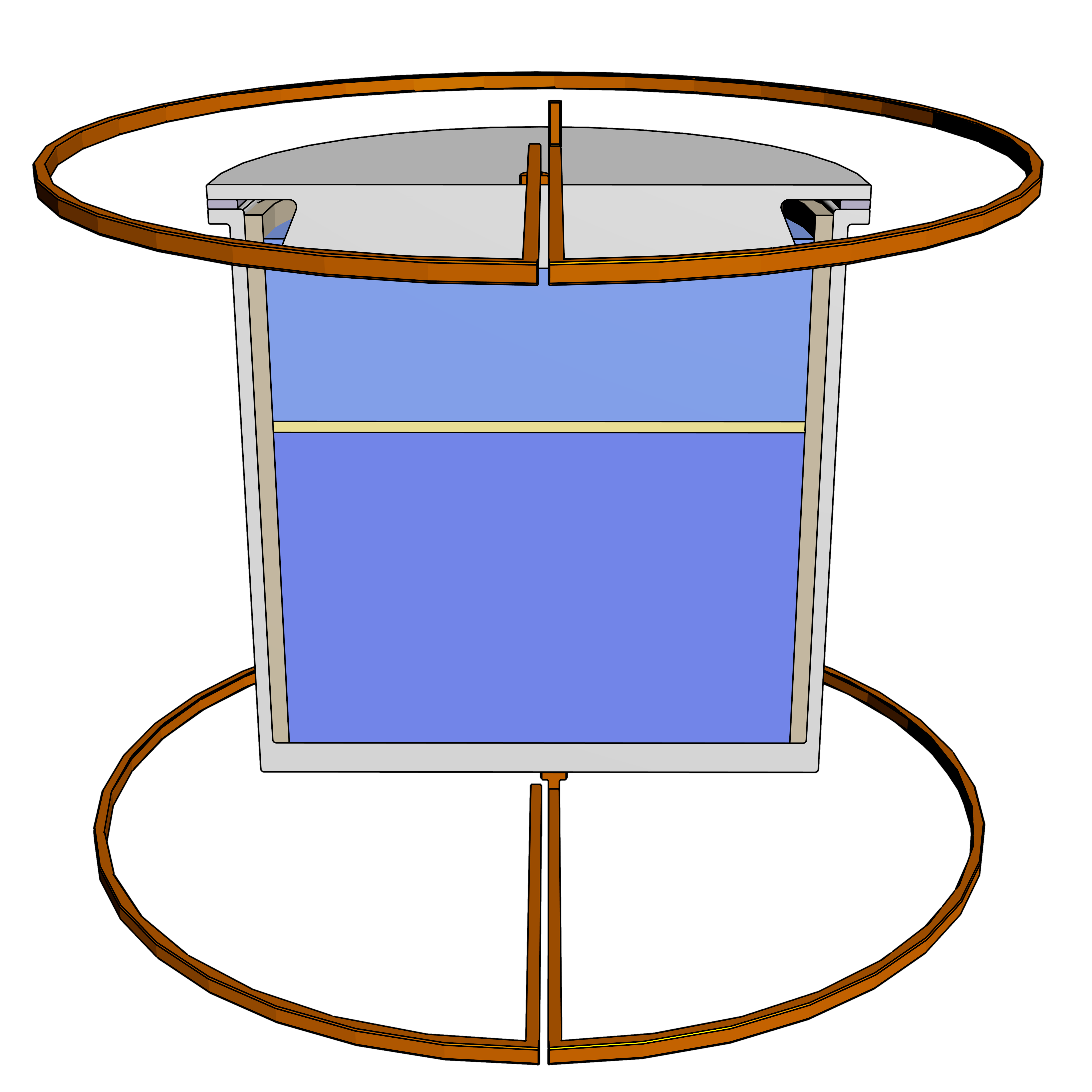
For a cuboid geometry and a rather large Helmholtz coil, the lower, dashed straight line in Fig. 12 corresponds now to the situation that the total battery current is also used in the coil, i.e. . Evidently, the critical current, as shown in the upper curve, increases with the coil current in such a way that there is always a large margin between the actual battery current and the critical current. This means, in turn, that for suppressing the TI it would be sufficient to use only a part of the (dashed) battery current in the Helmholtz-like coil. This is indicated by the straight dotted curve in the middle, which corresponds to the relation . This is indeed of technical relevance since it allows to split the current into a small part going through the coil and a larger part going through an appropriate short-cut, thereby decreasing significantly the total voltage drop.

We note here that the configuration shown in Fig. 11 is only a typical example. One can well imagine to use only one single winding, positioned approximately in the middle of the battery height.
3.5 Horizontal magnetic field
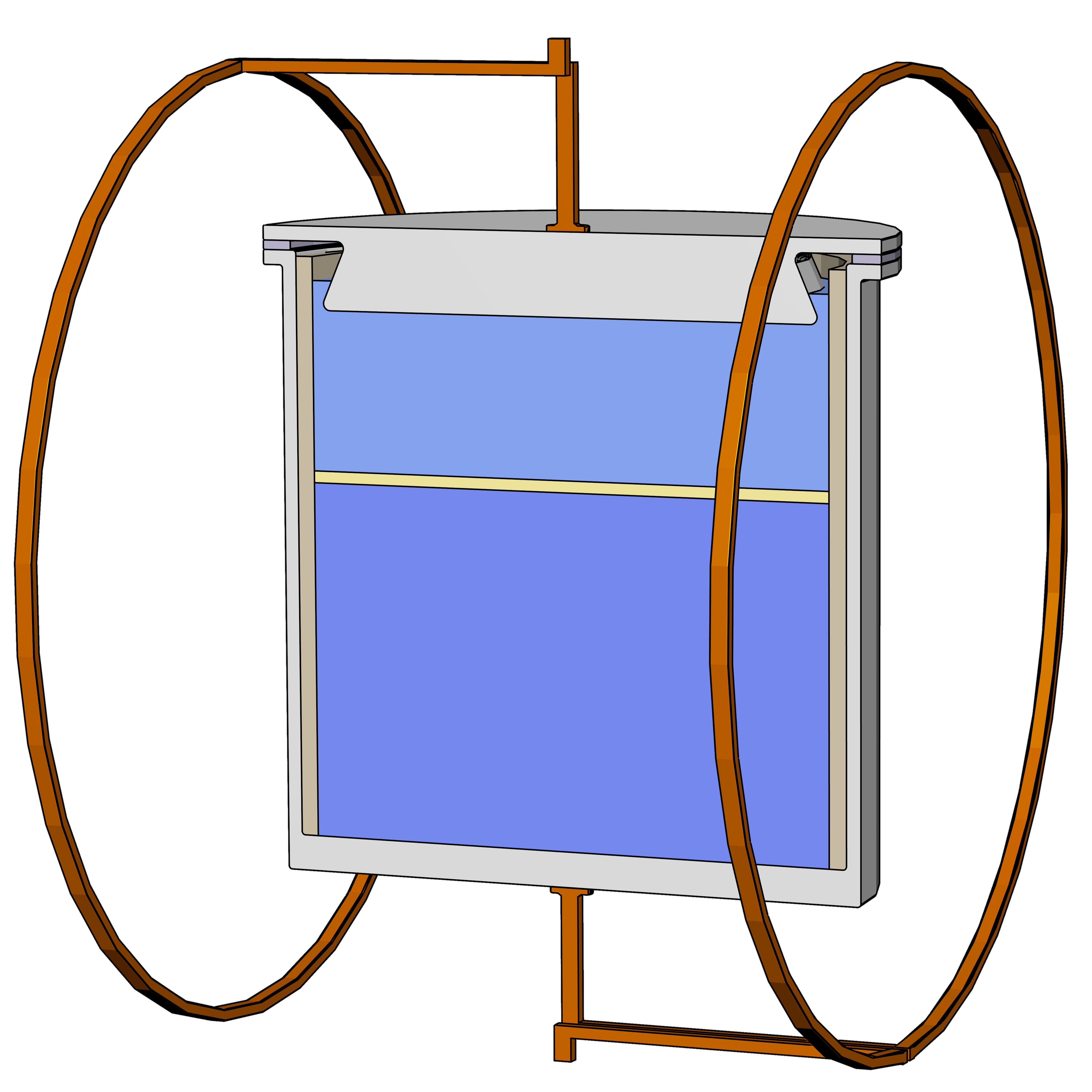
If an axial magnetic field works so well in suppressing the TI, we may ask if this functions also for an applied horizontal magnetic field (Fig. 13). Evidently, this is the case (see Fig. 14), although the critical current is not as steeply increasing with the coil current as for the case of an axial field. Yet, for certain stacked configurations of batteries even this stabilization method might have advantages.

4 Summary and outlook
In this paper we have considered the susceptibility of large-scale liquid metal batteries to magnetohydrodynamic instabilities that are driven by the charging or discharging currents.
Our main focus was on the kink-type Tayler instability that may become relevant for batteries with medium or large aspect ratios. First, we have characterized the dependence of the TI on several material parameters. For this purpose we have utilized a new numerical code that allows to treat the TI for finite size geometries and for realistic material parameters of liquid metals. Not surprisingly, all the concrete parameter dependencies turned out to collapse into a universal dependence of the normalized growth rate and the Reynolds number on the Hartmann number.
In the main part of the paper, we have delineated five possible measures for suppressing the TI. In the first two methods we have varied the geometry of the liquid metal columns, either by reducing its height, or by inserting a central electrically insulating tube. The last three methods utilized the fact that externally applied magnetic fields are able to damp or even to suppress the TI. This has been exemplified by showing that both a counter-current in the central bore as well as an axial or a horizontal magnetic field may re-stabilize the flow. In either case we have indicated possible technical realizations, with some focus on minimizing the material and/or the voltage drops in the necessary additional wires.
Having focused on the current driven TI, we have to keep in mind the additional relevance of interface instabilities which are well known from aluminum production cells [15]. The detailed investigation of those instabilities, and of their possible interaction with the TI, must be left for future work. This interaction aspect is highly non-trivial because measures that seem ideally suited for suppressing the TI (i.e. applying an axial field) might, in turn, lead to an enhancement of the interface instabilities. Numerical work on this interaction is presently in progress.
Acknowledgment
This work was supported by Helmholtz-Gemeinschaft Deutscher Forschungszentren (HGF) in the frame of “Initiative für mobile und stationäre Energiespeichersysteme” as well as in the frame of Helmholtz Alliance “Liquid metal technologies” (LIMTECH). Fruitful discussions with Marcus Gellert, Jānis Priede, Günther Rüdiger, Martin Seilmayer, Steffen Landgraf and Andreas Bund on several aspects of the TI and liquid metal batteries are grateful acknowledged.
References
- Wadia et al. [2011] C. Wadia, P. Albertus, V. Srinivasan, J. Power Sources 196 (2011) 1593–1598.
- Bradwell et al. [2012] D. J. Bradwell, H. Kim, A. H. C. Sirk, D. R. Sadoway, J. Am. Chem. Soc. 134 (2012) 1895–1897.
- Swinkels [1971] D. A. J. Swinkels, in: J. Braunstein, G. Mamantov, G. P. Smith (Eds.), Advances in Molten Salt Chemistry, volume 1, Plenum Press, New York, 1971, pp. 165–223.
- Steunenberg and Burris [2000] R. K. Steunenberg, L. Burris, From Test Tube to Pilot Plant: A 50 Year History of the Chemical Technology Division at Argonne National Laboratory, Technical Report ANL-00/16, Argonne National Laboratory, 2000.
- Weaver et al. [1962] R. D. Weaver, S. W. Smith, N. L. Willmann, J. Electrochem. Soc. 109 (1962) 653–657.
- Agruss [1963] B. Agruss, J. Electrochem. Soc. 110 (1963) 1097–1103.
- Henderson [1963] R. E. Henderson, in: Conf. on Direct Energy Conversion, University of Chicago, pp. 49–52. ANL-6802.
- Crouthamel and Recht [1967] C. Crouthamel, H. Recht (Eds.), Regenerative EMF Cells, American Chemical Society, 1967.
- Cairns et al. [1967] E. J. Cairns, C. E. Crouthamel, A. K. Fischer, M. S. Foster, J. C. Hesson, C. E. Johnson, H. Shimotake, A. D. Tevebaugh, Galvanic Cells with Fused-Salt Electrolytes, ANL-7316, Argonne National Laboratory, 1967.
- Cairns and Shimotake [1969] E. Cairns, H. Shimotake, Science 164 (1969) 1347–1355.
- Kim et al. [2013a] H. Kim, D. A. Boysen, J. M. Newhouse, B. L. Spatocco, B. Chung, P. J. Burke, D. J. Bradwell, K. Jiang, A. A. Tomaszowska, K. Wang, W. Wei, L. A. Ortiz, S. A. Barriga, S. M. Poizeau, D. R. Sadoway, Chem. Rev. 113 (2013a) 2075–2099.
- Kim et al. [2013b] H. Kim, D. A. Boysen, T. Ouchi, D. R. Sadoway, J. Power Sources 241 (2013b) 239–248.
- Sele [1977] T. Sele, Metall. Mater. Trans. B 8 (1977) 613–618.
- Bojarevics and Romerio [1994] V. Bojarevics, M. V. Romerio, Eur. J. Mech. B/Fluids 13 (1994) 33–56.
- Davidson [2000] P. Davidson, Mater. Sci. Technol. 16 (2000) 475–479.
- Evans and Ziegler [2007] J. W. Evans, D. P. Ziegler, in: A. Bard, M. Stratmann (Eds.), Encyclopedia of Electrochemistry, volume 5, Wiley-VCH, Weinheim, 2007, pp. 224–265. Volume editors: Macdonald, D.D. and Schmuki, P.
- Molokov et al. [2011] S. Molokov, G. El, A. Lukyanov, Theor. Comput. Fluid Dyn. 25 (2011) 261–279.
- Sneyd [1985] A. Sneyd, J. Fluid Mech. 156 (1985) 223–236.
- Dube [1954] M. C. Dube, in: B. Nijhawan, A. Chatterjee (Eds.), Proc. Symp. Non-ferrous metal industry in India, National Metallurgical Laboratory, Jamshedpur, India, pp. 127–138. Symposium date: Feb 1.-3., 1954; published 1957.
- Srinivasan et al. [1986] K. Srinivasan, C. Augustin, K. Dandapani, A. Selvakesavan, G. Kannan, S. Sukumaran, L. Srinivasan, P. Subramanian, T. Devasahayam, N. Rajagopalan, S. Srikantan, P. Desikan, K. Vasu, Bul. Electrochem. 2 (1986) 621–623.
- Edwards et al. [1930] J. Edwards, F. Frary, Z. Jeffries, Aluminum and its production, McGraw-Hill, New York and London, 1930.
- Sadoway et al. [2012] D. Sadoway, G. Ceder, D. Bradwell, High-amperage energy storage device with liquid metal negativ electrode and methods, US Patent 8,268,471 B2, 2012.
- Seilmayer et al. [2012] M. Seilmayer, F. Stefani, T. Gundrum, T. Weier, G. Gerbeth, M. Gellert, G. Rüdiger, Phys. Rev. Lett. 108 (2012) 244501.
- Weber et al. [2013] N. Weber, V. Galindo, F. Stefani, T. Weier, T. Wondrak, New J. Phys. 15 (2013) 043034.
- Meir et al. [2004] A. J. Meir, P. G. Schmidt, S. I. Bakhtiyarov, R. A. Overfelt, J. Appl. Mech. 71 (2004) 786–795.
- Stefani et al. [2011] F. Stefani, T. Weier, T. Gundrum, G. Gerbeth, Energ. Convers. Manage. 52 (2011) 2982–2986.
- Herédy et al. [1967] L. A. Herédy, M. L. Iverson, G. D. Ulrich, H. L. Recht, in: [8], pp. 30–42.
- Agruss and Karas [1967] B. Agruss, H. R. Karas, in: [8], pp. 62–81.
- Shimotake and Cairns [1967] H. Shimotake, E. J. Cairns, in: Advances in Energy Conversion Engineering: Papers, Critiques and Summaries from he Intersociety Energy Conversion Engineering Conference held at Miami Beach, Florida, August 13-17, ASME, pp. 951–962.
- Foster [1967] M. S. Foster, in: [8], pp. 136–148.
- Rüdiger et al. [2011] G. Rüdiger, M. Schultz, M. Gellert, Astron. Nachr. 332 (2011) 17–23.
- Tayler [1973] R. J. Tayler, Mon. Not. R. astr. Soc. 161 (1973) 365–380.
- Bergerson et al. [2006] W. F. Bergerson, C. B. Forest, G. Fiksel, D. A. Hannum, R. Kendrick, J. S. Sarff, S. Stambler, Phys. Rev. Lett. 96 (2006) 015004.
- Stefani et al. [2012] F. Stefani, S. Eckert, G. Gerbeth, A. Giesecke, T. Gundrum, C. Steglich, T. Weier, B. Wustmann, Magnetohydrodynamics 48 (2012) 103–113.
- Stefani et al. [2009] F. Stefani, G. Gerbeth, T. Gundrum, R. Hollerbach, J. Priede, G. Rüdiger, J. Szklarski, Phys. Rev. E 80 (2009) 066303.