Perfect and robust phase-locking of a spin transfer vortex nano-oscillator
to an external microwave source
Abstract
We study the synchronization of the auto-oscillation signal generated by the spin transfer driven dynamics of two coupled vortices in a spin-valve nanopillar to an external source. Phase-locking to the microwave field occurs in a range larger than 10% of the oscillator frequency for drive amplitudes of only a few Oersteds. Using synchronization at the double frequency, the generation linewidth is found to decrease by more than five orders of magnitude in the phase-locked regime (down to 1 Hz, limited by the resolution bandwidth of the spectrum analyzer) in comparison to the free running regime ( kHz). This perfect phase-locking holds for frequency detuning as large as 2 MHz, which proves its robustness. We also analyze how the free running spectral linewidth impacts the main characteristics of the synchronization regime.
Spin transfer nano-oscillators (STNOs) are nanoscale microwave generators Kiselev et al. (2003); Rippard et al. (2004) which have become very attractive due to their wide range of potential applications (frequency generation Houssameddine et al. (2007); Bonetti et al. (2009) and detection Tulapurkar et al. (2005); Zhu et al. (2012), signal processing Muduli et al. (2010); Pogoryelov et al. (2011), dynamic recording Mizushima et al. (2010); Zhu and Wang (2010)). The transfer of angular momentum from a spin-polarized current to a ferromagnetic layer can excite the gyrotropic mode of a magnetic vortex Pribiag et al. (2007); Mistral et al. (2008) having typical frequency between 20 MHz and 2 GHz Guslienko (2008). Vortex-based STNOs are very promising due to their narrow generation linewidth (about 1 MHz) and potentially high output power Dussaux et al. (2010). Recently, we have proposed a way to minimize even more the auto-oscillation linewidth by operating a STNO based on two coupled vortices in a spin-valve nanopillar, which can yield highly coherent signals () with linewidths under 50 kHz at room temperature and near zero magnetic field Locatelli et al. (2011).
Synchronization to an external periodic signal and mutual phase-locking of several STNOs have been proposed as means to increase the emitted power and reduce the phase noise of STNOs Slavin and Tiberkevich (2009). It has also been suggested that synchronized arrays of STNOs could be operated as associative memories Shibata et al. (2012). So far, mutual phase-locking has been achieved using spin wave coupling between nanocontacts Kaka et al. (2005); Mancoff et al. (2005); Sani et al. (2013) and 2D arrays of vortices and anti-vortices Ruotolo et al. (2009). It is also predicted to occur using the common microwave current emitted Slavin and Tiberkevich (2005); Grollier et al. (2006) or the dipolar interaction between adjacent STNOs Belanovsky et al. (2012); Erokhin and Berkov . To demonstrate the efficiency of these two types of coupling, synchronization to an external microwave current passing through the device Rippard et al. (2005); Georges et al. (2008); Quinsat et al. (2011); Dussaux et al. (2011) or to a microwave field produced by an external antenna Urazhdin et al. (2010); Hamadeh et al. (2012) have been studied.
Two key characteristics to analyze the quality of the synchronization are the locking range and the generation linewidth in the phase-locked regime, which are respectively related to the coupling efficiency and the response to noise of the oscillator. In a single vortex-based tunneling magnetoresistance (TMR) device, it was shown that using an external microwave current, the locking range could reach up to one third of the oscillator frequency, and the linewidth be reduced by 3 orders of magnitude, from a few MHz down to 3 kHz Dussaux et al. (2011). In this letter, we demonstrate perfect and robust synchronization of the microwave signal generated by the dynamics of two coupled vortices in a spin-valve nanopillar to an external microwave field . The linewidth measured in the phase-locked regime is indeed limited by the minimal resolution bandwidth (RBW) of the spectrum analyzer, which is 1 Hz. We observe such outstanding characteristics even for frequency detunings larger than ten times the free running linewidth (140 kHz).
The studied STNO is a circular nanopillar of diameter 250 nm patterned from a (Cu60Py15 Cu10Py4Au25) stack, where thicknesses are in nm and Py=Ni80Fe20. An insulating resist is deposited onto the STNO device and an external antenna is patterned on top to generate a spatially uniform microwave magnetic field oriented in the plane of the magnetic layers Naletov et al. (2011). By injecting a current through the STNO (electrons flowing from the thick to the thin Py layer), a vortex with chirality parallel to the orthoradial Oersted field is stabilized in each of the Py layers Locatelli et al. (2011); Sluka et al. (2012). A magnetic field is applied perpendicularly to the sample plane and the vortex core polarities are set to be anti-parallel (see inset of Fig.1b). For mA, a narrow microwave emission peak corresponding to the spin transfer driven dynamics of the two coupled vortices is detected on the spectrum analyzer. At fixed , the microwave characteristics of this auto-oscillation peak (frequency and linewidth) can be tuned by varying Hamadeh et al. . In this study, all measurements are carried out at room temperature.
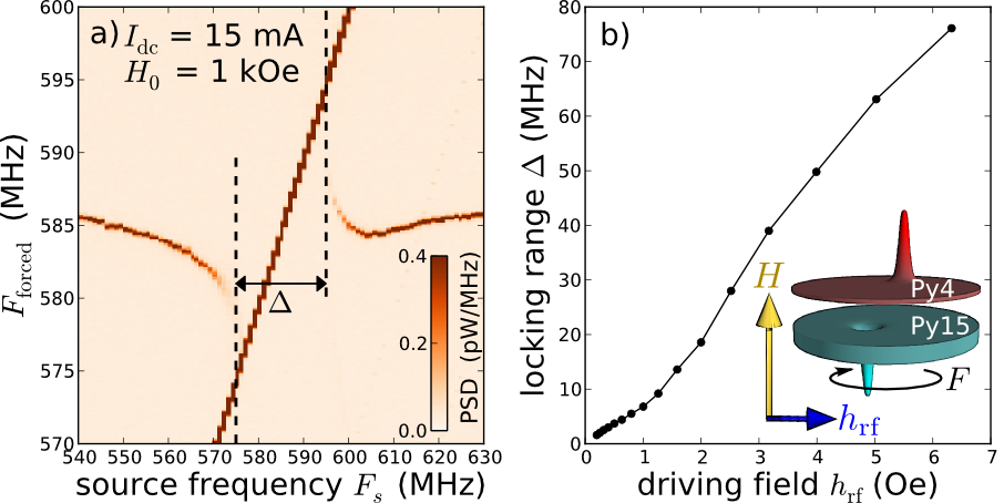
The perpendicular field is first set to kOe and the dc current fixed to mA. Under these bias conditions, the oscillator frequency is MHz and the generation linewidth kHz. In Fig.1a, we present a map of the power density when the frequency of the external microwave field is swept from 540 MHz to 630 MHz at constant drive amplitude Oe 111The output power from the synthetizer injected into the microwave antenna is set to dBm.. When comes closer to , the frequency of the oscillator is pulled towards the source frequency. When MHz, there is a single frequency peak in the spectrum, meaning that the auto-oscillation is synchronized to the external source. At this point, it is not possible to separate the signal of the gyrotropic oscillation and that of the source, which prevents measuring the generation linewidth in the phase-locked regime. This situation is observed until MHz, above which the oscillation frequency gradually shifts back to its free running value . The locking range measured experimentally is plotted vs. in Fig.1b. As expected Slavin and Tiberkevich (2009), it increases linearly with at low drive amplitude ( Oe). The behavior observed at larger is presumably due to some nonlinearities of the system. We point out that at Oe, the locking range MHz corresponds to 13% of the oscillator frequency .
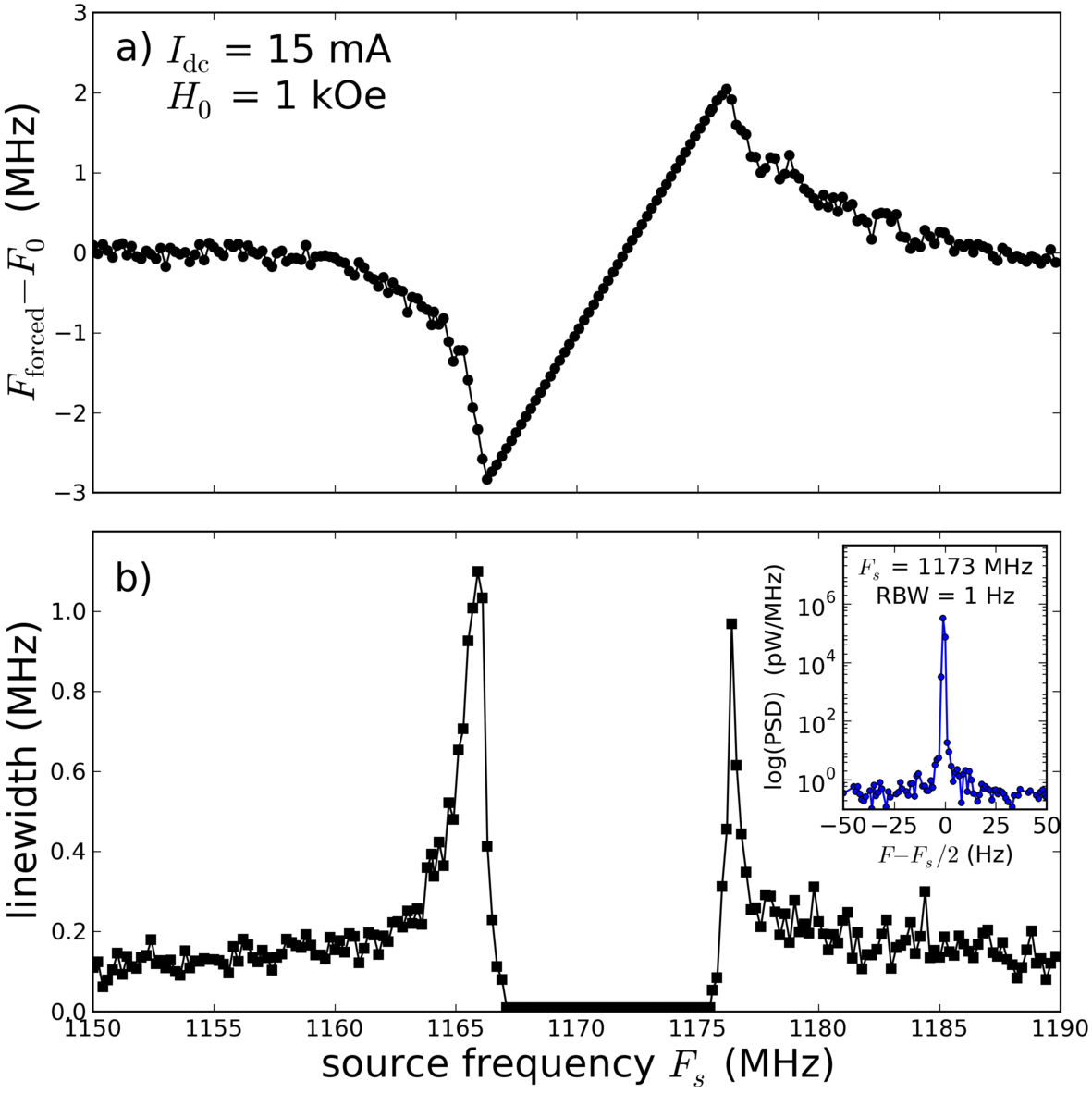
In order to measure the linewidth of the oscillator signal when its frequency is locked, the source frequency is now swept around . In Fig.2a, we plot the frequency shift of the oscillator when it is forced by the microwave field of amplitude Oe as a function of varying from 1150 MHz to 1190 MHz. As in Fig.1a, we observe the characteristic behavior of synchronization to the external source, except that it is now at twice the oscillator frequency and the oscillation signal is not hindered by the source signal. Hence, we can analyze the dependence of the generation linewidth on , which is plotted in Fig.2b. The striking observation is a dramatic reduction of the generation linewidth within the locking range. As shown in the inset of Fig.2b, the measured linewidth is indeed limited by the 1 Hz minimal RBW of the spectrum analyzer, i.e., the auto-oscillation is perfectly phase-locked to the external source. This corresponds to an improvement of the signal coherency by a factor greater than with respect to the free running case. The increase of the generation linewidth up to 1 MHz observed at the boundaries of the locking range is attributed to successive synchronization-unsynchronization events occurring at the timescale of the measurement Dussaux et al. (2011).
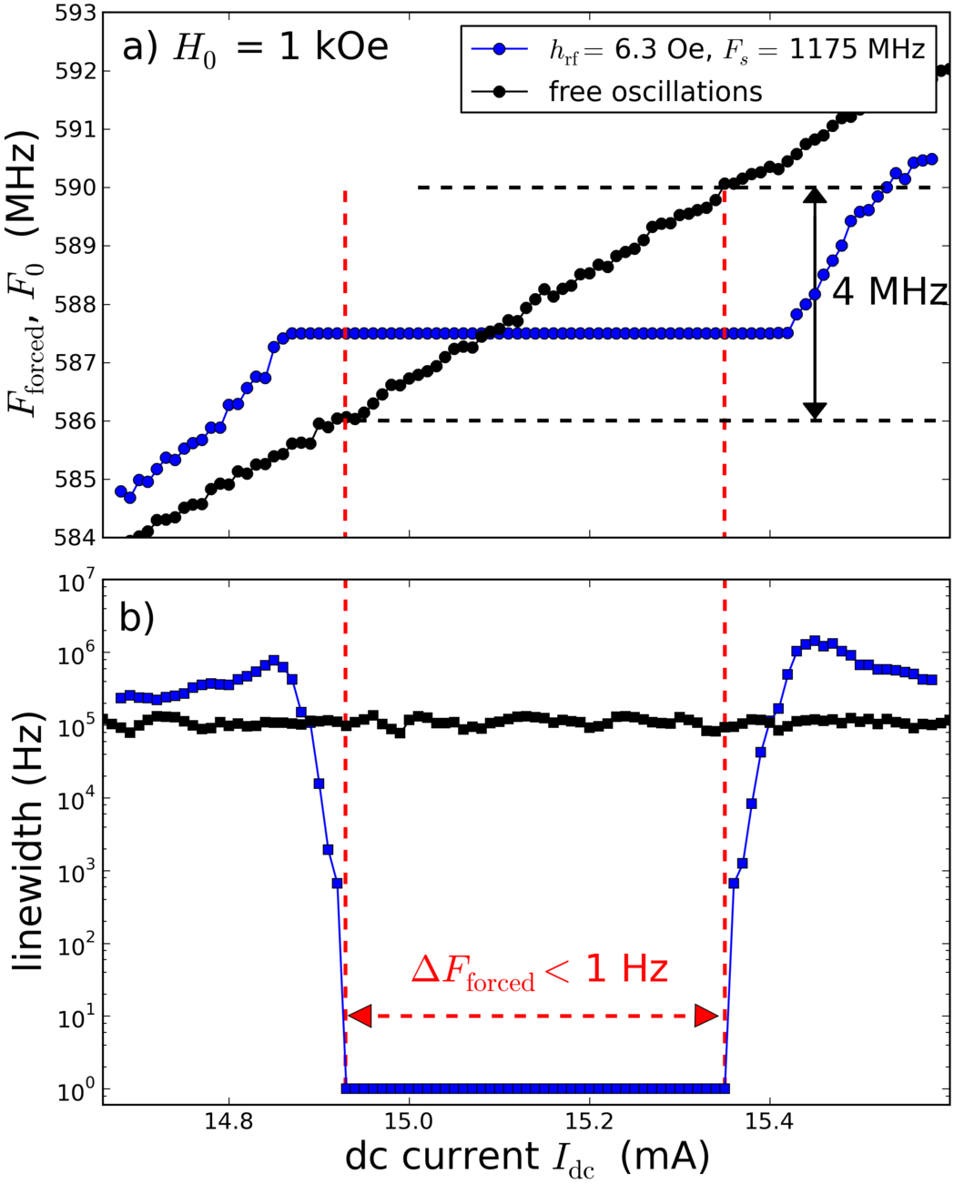
To gain further insight, we investigate the robustness of this perfect phase-locking. We now measure the auto-oscillation signal as a function of , which is swept from 14.6 mA to 15.6 mA. In the free regime (external source turned off), the generation frequency increases linearly from 584 MHz to 592 MHz, while the linewidth is nearly constant around kHz, as shown by the black dots in Figs.3a and b, respectively. The tunability observed in our vortex-based STNO, MHz/mA, results from the Oersted field created by the dc current Khvalkovskiy et al. (2009). In the forced regime with the external source turned on at MHz and Oe (see blue dots in Fig.3a), the auto-oscillation frequency is pulled towards half the source frequency for mA and mA, and constant and equal to in between these boundaries, which define the locking range. The associated decrease of the generation linewidth is spectacular, as shown by the logarithmic scale in Fig.3b. The measured linewidth is limited by the Hz for mA, which means that the phase-locking to the external source is perfect within this range of current. The latter corresponds to a variation by 4 MHz of the auto-oscillation frequency in the free regime. These features demonstrate the robustness of the synchronization observed in our sample, as it means that even if the external source frequency deviates from the oscillator frequency by more than ten times the free running linewidth, perfect phase-locking can still occur.
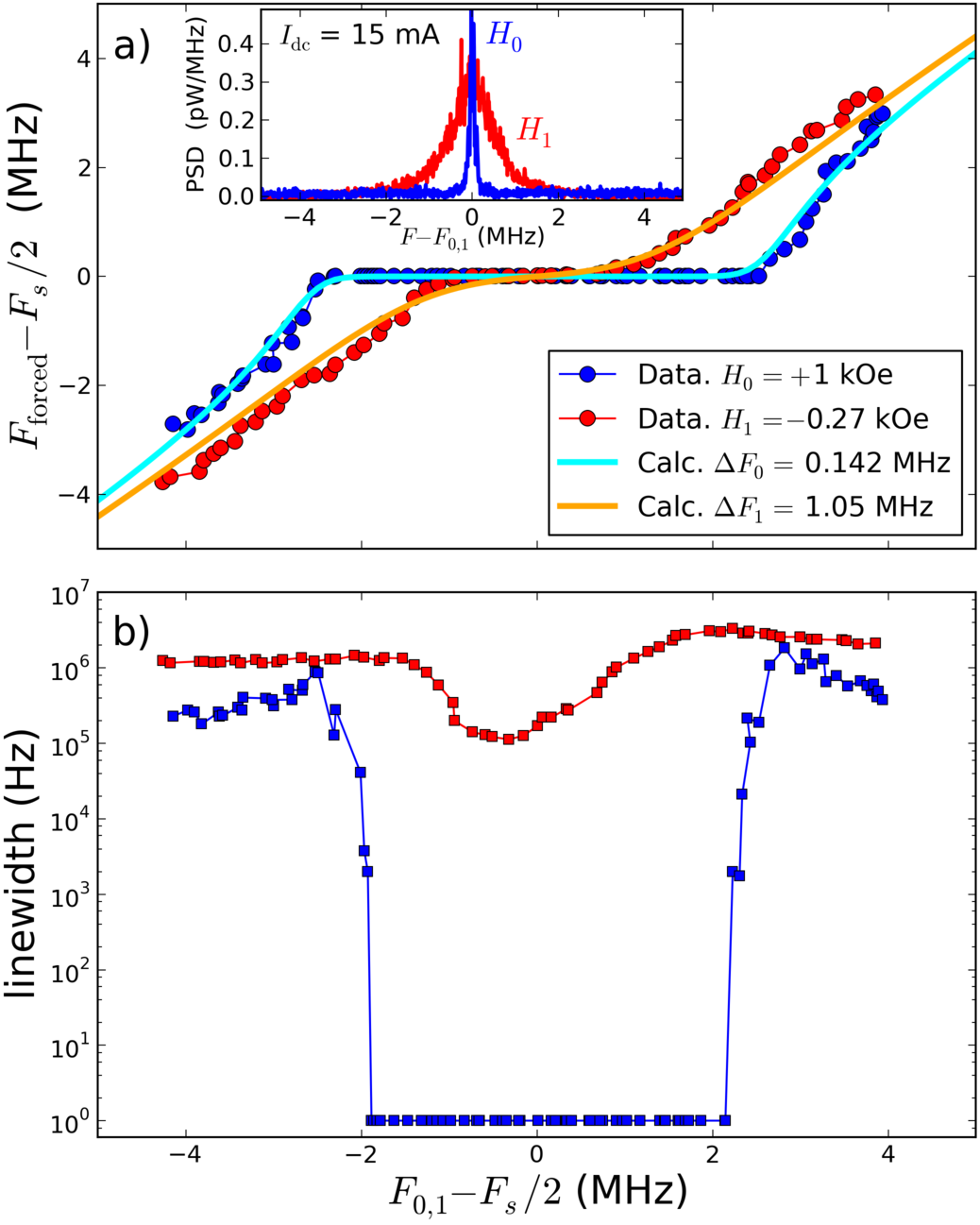
Another issue to investigate is the influence of fluctuations Grimaldi et al. on the actual characteristics of our vortex oscillator when it is phase-locked. To do that, we compare the synchronization of auto-oscillation signals having different generation linewidths. We use two different applied fields, kOe and kOe, at which the emission frequencies at mA slightly differ ( MHz and MHz, respectively), and the generation linewidth varies by more than a factor seven 222This change of linewidth is due to the influence of a lower frequency overdamped mode Hamadeh et al. ., from kHz to MHz (see inset of Fig.4a). Using blue and red dots at and , respectively, we plot the experimental frequency mismatch (Fig.4a) and the linewidth in the forced regime (Fig.4b) as a function of the detuning between the natural oscillator frequency and half the source frequency 333In these measurements, Oe and is varied from 14.6 mA to 15.6 mA. At , varies from 584 MHz to 592 MHz and is fixed to 1175 MHz. At , varies from 681 MHz to 689 MHz and is fixed to 1370 MHz.. The strong differences observed in the characteristics of the synchronization at these two fields reveal the role played by the fluctuations in the phase dynamics of STNOs. When the latter are weak (narrower generation linewidth at ), the locking range is large (more than 4 MHz) and the synchronized signal acquires the spectral quality of the source (less than 1 Hz). When the noise is larger (broader generation linewidth at ), it competes against the coupling to the external source, which results in a smaller apparent locking range and a poorest spectral quality of the forced oscillation. Here, increasing the linewidth by a factor has a huge influence on the signal coherency in the phase-locked regime since its improvement with respect to the free running case drops from a factor to only 10. The influence of phase fluctuations on the frequency mismatch has been modeled by Eq.(5) of Ref.Georges et al. (2008) (see continuous lines in Fig.4a). Using the measured linewidths and in this equation, the only fitting parameter is the coupling strength of the external microwave source to the oscillator (equal to half the locking range in the case of zero fluctuations), which is found to be MHz both at and .
In conclusion, we have shown that the microwave signal generated by a STNO based on coupled vortices can be efficiently synchronized to an external microwave field. The relative locking range indeed exceeds 10% for small drive amplitudes ( Oe) and the auto-oscillation signal acquires the spectral purity of the source, corresponding to an improvement of its coherency by a factor greater than . Moreover, this perfect phase-locking is robust, as it survives even when the external frequency deviates from the oscillator frequency by more than ten times its linewidth. We believe that the efficient synchronization of vortex-based STNOs to the microwave field is very promising for the idea of mutually coupling such oscillators through the dipolar interaction Belanovsky et al. (2013).
This research was partly funded by the French ANR (grant SPINNOVA ANR-11-NANO-0016) and the EU (FP7 grant MOSAIC ICT-FP7-317950).
References
- Kiselev et al. (2003) S. I. Kiselev, J. C. Sankey, I. N. Krivorotov, N. C. Emley, R. J. Schoelkopf, R. A. Buhrman, and D. C. Ralph, Nature 425, 380 (2003).
- Rippard et al. (2004) W. H. Rippard, M. R. Pufall, S. Kaka, S. E. Russek, and T. J. Silva, Phys. Rev. Lett. 92, 027201 (2004).
- Houssameddine et al. (2007) D. Houssameddine, U. Ebels, B. Delaët, B. Rodmacq, I. Firastrau, F. Ponthenier, M. Brunet, C. Thirion, J.-P. Michel, L. Prejbeanu-Buda, M.-C. Cyrille, O. Redon, and B. Dieny, Nature Mater. 6, 447 (2007).
- Bonetti et al. (2009) S. Bonetti, P. Muduli, F. Mancoff, and J. Akerman, Appl. Phys. Lett. 94, 102507 (2009).
- Tulapurkar et al. (2005) A. A. Tulapurkar, Y. Suzuki, A. Fukushima, H. Kubota, H. Maehara, K. Tsunekawa, D. D. Djayaprawira, N. Watanabe, and S. Yuasa, Nature 438, 339 (2005).
- Zhu et al. (2012) J. Zhu, J. A. Katine, G. E. Rowlands, Y.-J. Chen, Z. Duan, J. G. Alzate, P. Upadhyaya, J. Langer, P. K. Amiri, K. L. Wang, and I. N. Krivorotov, Phys. Rev. Lett. 108, 197203 (2012).
- Muduli et al. (2010) P. K. Muduli, Y. Pogoryelov, S. Bonetti, G. Consolo, F. Mancoff, and J. Åkerman, Phys. Rev. B 81, 140408 (2010).
- Pogoryelov et al. (2011) Y. Pogoryelov, P. K. Muduli, S. Bonetti, E. Iacocca, F. Mancoff, and J. Åkerman, Appl. Phys. Lett. 98, 192501 (2011).
- Mizushima et al. (2010) K. Mizushima, K. Kudo, T. Nagasawa, and R. Sato, Journal of Applied Physics 107, 063904 (2010).
- Zhu and Wang (2010) J.-G. Zhu and Y. Wang, IEEE Trans. Magn. 46, 751 (2010).
- Pribiag et al. (2007) V. S. Pribiag, I. N. Krivorotov, G. D. Fuchs, P. M. Braganca, O. Ozatay, J. C. Sankey, D. C. Ralph, and R. A. Buhrman, Nature Phys. 3, 498 (2007).
- Mistral et al. (2008) Q. Mistral, M. van Kampen, G. Hrkac, J.-V. Kim, T. Devolder, P. Crozat, C. Chappert, L. Lagae, and T. Schrefl, Phys. Rev. Lett. 100, 257201 (2008).
- Guslienko (2008) K. Y. Guslienko, J. Nanosci. Nanotechnol. 8, 2745 (2008).
- Dussaux et al. (2010) A. Dussaux, B. Georges, J. Grollier, V. Cros, A. Khvalkovskiy, A. Fukushima, M. Konoto, H. Kubota, K. Yakushiji, S. Yuasa, K. Zvezdin, K. Ando, and A. Fert, Nat. Commun. 1, 8 (2010).
- Locatelli et al. (2011) N. Locatelli, V. V. Naletov, J. Grollier, G. de Loubens, V. Cros, C. Deranlot, C. Ulysse, G. Faini, O. Klein, and A. Fert, Appl. Phys. Lett. 98, 062501 (2011).
- Slavin and Tiberkevich (2009) A. Slavin and V. Tiberkevich, IEEE Trans. Magn. 45, 1875 (2009).
- Shibata et al. (2012) T. Shibata, R. Zhang, S. Levitan, D. Nikonov, and G. Bourianoff, in Cellular Nanoscale Networks and Their Applications (CNNA), 2012 13th International Workshop on (2012) pp. 1–5.
- Kaka et al. (2005) S. Kaka, M. R. Pufall, W. H. Rippard, T. J. Silva, S. E. Russek, and J. A. Katine, Nature (London) 437, 389 (2005).
- Mancoff et al. (2005) F. B. Mancoff, N. D. Rizzo, B. N. Engel, and S. Tehrani, Nature (London) 437, 393 (2005).
- Sani et al. (2013) S. Sani, J. Persson, S. Mohseni, Y. Pogoryelov, P. Muduli, A. Eklund, G. Malm, M. Käll, A. Dmitriev, and J. Akerman, Nature Communications 4, 2731 (2013).
- Ruotolo et al. (2009) A. Ruotolo, V. Cros, B. Georges, A. Dussaux, J. Grollier, C. Deranlot, R. Guillemet, K. Bouzehouane, S. Fusil, and A. Fert, Nature Nanotech. 4, 528 (2009).
- Slavin and Tiberkevich (2005) A. N. Slavin and V. S. Tiberkevich, Phys. Rev. B 72, 092407 (2005).
- Grollier et al. (2006) J. Grollier, V. Cros, and A. Fert, Phys. Rev. B 73, 060409 (2006).
- Belanovsky et al. (2012) A. D. Belanovsky, N. Locatelli, P. N. Skirdkov, F. A. Araujo, J. Grollier, K. A. Zvezdin, V. Cros, and A. K. Zvezdin, Phys. Rev. B 85, 100409 (2012).
- (25) S. Erokhin and D. Berkov, arXiv:1302.0659 .
- Rippard et al. (2005) W. H. Rippard, M. R. Pufall, S. Kaka, T. J. Silva, S. E. Russek, and J. A. Katine, Phys. Rev. Lett. 95, 067203 (2005).
- Georges et al. (2008) B. Georges, J. Grollier, M. Darques, V. Cros, C. Deranlot, B. Marcilhac, G. Faini, and A. Fert, Phys. Rev. Lett. 101, 017201 (2008).
- Quinsat et al. (2011) M. Quinsat, J. F. Sierra, I. Firastrau, V. Tiberkevich, A. Slavin, D. Gusakova, L. D. Buda-Prejbeanu, M. Zarudniev, J.-P. Michel, U. Ebels, B. Dieny, M.-C. Cyrille, J. A. Katine, D. Mauri, and A. Zeltser, Appl. Phys. Lett. 98, 182503 (2011).
- Dussaux et al. (2011) A. Dussaux, A. V. Khvalkovskiy, J. Grollier, V. Cros, A. Fukushima, M. Konoto, H. Kubota, K. Yakushiji, S. Yuasa, K. Ando, and A. Fert, Appl. Phys. Lett. 98, 132506 (2011).
- Urazhdin et al. (2010) S. Urazhdin, P. Tabor, V. Tiberkevich, and A. Slavin, Phys. Rev. Lett. 105, 104101 (2010).
- Hamadeh et al. (2012) A. Hamadeh, G. de Loubens, V. V. Naletov, J. Grollier, C. Ulysse, V. Cros, and O. Klein, Phys. Rev. B 85, 140408 (2012).
- Naletov et al. (2011) V. V. Naletov, G. de Loubens, G. Albuquerque, S. Borlenghi, V. Cros, G. Faini, J. Grollier, H. Hurdequint, N. Locatelli, B. Pigeau, A. N. Slavin, V. S. Tiberkevich, C. Ulysse, T. Valet, and O. Klein, Phys. Rev. B 84, 224423 (2011).
- Sluka et al. (2012) V. Sluka, A. Kákay, A. M. Deac, D. E. Bürgler, R. Hertel, and C. M. Schneider, Phys. Rev. B 86, 214422 (2012).
- (34) A. Hamadeh, G. de Loubens, O. Klein, V. Naletov, N. Locatelli, R. Lebrun, J. Grollier, and V. Cros, arXiv:1310.4913 .
- Note (1) The output power from the synthetizer injected into the microwave antenna is set to dBm.
- Khvalkovskiy et al. (2009) A. V. Khvalkovskiy, J. Grollier, A. Dussaux, K. A. Zvezdin, and V. Cros, Phys. Rev. B 80, 140401 (2009).
- (37) E. Grimaldi, A. Dussaux, P. Bortolotti, J. Grollier, G. Pillet, A. Fukushima, H. Kubota, K. Yakushiji, S. Yuasa, and V. Cros, arXiv:1311.6299 .
- Note (2) This change of linewidth is due to the influence of a lower frequency overdamped mode Hamadeh et al. .
- Note (3) In these measurements, Oe and is varied from 14.6 mA to 15.6 mA. At , varies from 584 MHz to 592 MHz and is fixed to 1175 MHz. At , varies from 681 MHz to 689 MHz and is fixed to 1370 MHz.
- Belanovsky et al. (2013) A. D. Belanovsky, N. Locatelli, P. N. Skirdkov, F. Abreu Araujo, K. A. Zvezdin, J. Grollier, V. Cros, and A. K. Zvezdin, Appl. Phys. Lett. 103, 122405 (2013).