Protected Josephson Rhombi Chains
Abstract
We have studied the low-energy excitations in a minimalistic protected Josephson circuit which contains two basic elements (rhombi) characterized by the periodicity of the Josephson energy. Novel design of these elements, which reduces their sensitivity to the offset charge fluctuations, has been employed. We have observed that the life time of the first excited state of this quantum circuit in the protected regime is increased up to 70, a factor of longer than that in the unprotected state. The quality factor of this qubit exceeds . Our results are in agreement with theoretical expectations; they demonstrate the feasibility of symmetry protection in the rhombi-based qubits fabricated with existing technology.
Quantum computing requires the development of quantum bits (qubits) with a long coherence time and the ability to manipulate them in a fault tolerant manner (see, e.g. Knill05 and references therein). Both goals can be achieved by the realization of a protected logical qubit formed by a collective state of an array of faulty qubits Kitaev20032 ; ioffe2002a ; Ioffe2002b ; doucot2002a ; doucot2003 ; doucot2005 . The building block (i.e. the faulty qubit) of the array is the Josephson element with an effective Josephson energy , which is - periodic in the phase difference across the element. In contrast to the conventional Josephson junctions with , this element supports the coherent transport of pairs of Copper pairs (the “4e” transport), whereas single Cooper pairs are localized and the “2e” transport is blocked doucot2002a ; protopopov2004 ; protopopov2006 . Though this proposal has attracted considerable theoretical attention brooks2013 , the experimental realization of a protected qubit was lacking.
In this Letter we make an essential step towards building a protected Josephson qubit by fabricating the simplest protected circuit and demonstrating that the first excited state of the circuit is protected from energy relaxation.
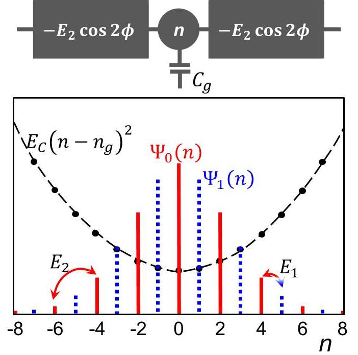
The idea of protection is illustrated in Fig.1. Let us consider the simplest chain of two elements. They share the central superconducting island whose charge is controlled by the gate. The Hamiltonian of this quantum circuit can be written as
| (1) |
where the energy describes the Josephson coupling of the central superconducting island to the current leads, is the effective charging energy of the island, is the number of Cooper pairs on the island, is the charge induced on the island by the gate. The parity of is preserved if the transfer of single Cooper pairs is blocked (). In this case the states of the system can be characterized by the quantum number . The low energy states corresponding to number are shown in Fig.1. The energy plays the role of the kinetic term that controls the “spread” of the wave functions along the axis. Provided , the number of components with different in these discrete Gaussian wavefunctions is large: , and the energy difference between the two states, , is exponentially small (see doucot2012 and Supplementary Material 1):
| (2) |
Here , is the plasma frequency, (Supplementary Material 1). Furthermore, these states cannot be distinguished by the noise operators, and, thus, the decay and dephasing rates are both reduced by the same large factor .
In real circuits, the 2e processes are not completely suppressed, and a non-zero amplitude mixes the odd and even components (Fig.1) and increases . For a small amplitude the decay of the first excited state is due to the mixture of states and is suppressed by the factor in addition to the suppression by the factor that is common to decay and dephasing. Thus, for the coherence protection two conditions are required: (i.e. slow energy relaxation) and (i.e. small dephasing rate).
The simplest Josephson elements is represented by the Josephson rhombus: a superconducting loop interrupted by four identical Josephson junctions doucot2002a ; protopopov2004 ; protopopov2006 ; gladchenko ; pop2008 (Fig.2a). When the rhombus is threaded by the magnetic flux ( is the flux quantum), its effective Josephson energy becomes -periodic in the phase difference across the rhombus, . In line with theoretical predictions, recent experiments gladchenko have demonstrated that the properly designed small rhombi arrays can support a non-zero 4e supercurrent in the regime when the 2e supercurrent vanishes.
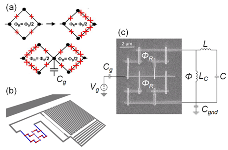
In the current work, we have implemented the two-rhombi chain with an improved design of individual rhombi proposed in Ref. doucot2012 . The key requirement for the protection is the cancellation of due to the destructive interference between the Cooper pair transfer amplitudes along the upper and lower branches of a rhombus. This cancellation is difficult to achieve in the quantum regime where the amplitudes depend on the uncontrolled offset charges on the side islands. This dependence is due to the Aharonov-Casher effect (see e.g. pop2012 ) and the high probability of phase slips across the two small junctions in each arm of a rhombus. In the improved rhombus design doucot2012 one junction in each branch is replaced by a short chain of larger junctions (Fig.2a). The phase slips across the larger junctions are suppressed due to a large ratio ( for the studied devices). As a result, an improved rhombus becomes insensitive to the offset charges on all islands except for the central island shared by both rhombi. Below we refer to the characteristic energies of the smaller and larger junctions as , and , respectively. An optimal operation of the rhombus is realized for and , where is the number of larger junctions in the chain ( for the studied devices).
The chains, the readout circuits, and the microwave (MW) transmission line were fabricated using multi-angle electron-beam deposition of Al films through a lift-off mask (for fabrication details see Refs. bell2012 ; bell2012a ). The in-plane dimensions of the small and large junctions were and , respectively. The ratio was chosen to realize the resonance frequency of the transition, , within the () GHz range. Below we show the data for one representative device with , , , and (throughout the paper all energies are given in the frequency units, ).
The readout lumped-element resonator was formed by the meandered 2-m-wide Al wire with the kinetic inductance nH and an interdigitated capacitor fF. The resonator was coupled to the chain via a narrow superconducting wire with a kinetic inductance of . The chain and the wire formed a superconducting loop; the flux of the external magnetic field in this phase loop controlled the phase difference across the chain (Fig.2c). Because the phase loop area () was much greater than the rhombus area (), the phase across the chain could be varied at an approximately constant value of . Several devices with systematically varied values of and were fabricated on the same chip and inductively coupled to the same microstrip line (Fig.2b). The devices could be individually addressed due to different resonance frequencies of the resonators. All measurements have been performed at =20 mK.
In the experiment, the microwaves traveled along the microstrip line inductively coupled to the device. The microwaves at the frequency probed the resonance. The microwaves at the second-tone frequency excited the transitions between the quantum states of the chain, which resulted in a change of the impedance of this non-linear system. The chain excitations were detected as a change in the amplitude and the phase of the microwaves at the probe-tone frequency (for measurement details, see Supplementary Material 2).
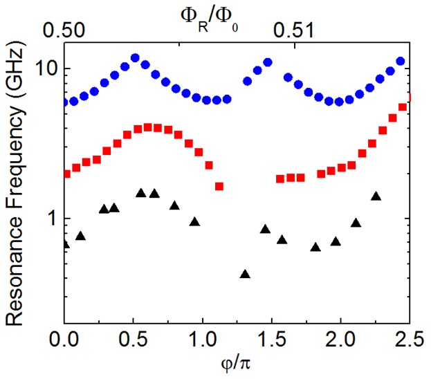
Below we focus on the most interesting range of magnetic fields close to full frustration (), where each rhombus represents a Josephson element. The measurements at the probe-tone frequency (no microwaves at ) show that in this regime the response of the chain to the phase difference is indeed periodic with the period (see Supplementary Material 3).
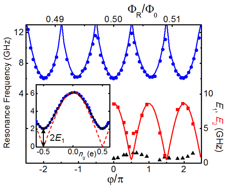
Figure 3 summarizes the spectroscopic data obtained in the two-tone measurements. The inset in Fig. 3 shows the resonance frequency measured as a function of at a fixed magnetic flux , . Note that during the data accuisition time for the inset in Fig.3 ( hours), no long-term shifts in the offset charge were observed. Also, quasiparticle poisoning was strongly suppressed due to (a) a larger superconducting gap of the central island (in comparison with the nearest-neighbor islands) and a relatively large aumentado2004 ; bell2012 , and (b) shielding of the device from stray infra-red photons by the double-wall light-tight sample holder (see, e.g. devisser2011 ).
For perfectly symmetric rhombi, the two states corresponding to (odd and even number of Cooper pairs on the central island) should become degenerate () at . Slight asymmetry of the studied rhombi results in a non-zero (see also Supplementary Material 4). At and , is equal to the effective charging energy . The non-zero energy suppresses (2) to 6.7 GHz. The energies ,, and were obtained from the experimental dependences measured at different values of by fitting them with the computations of the spectra based on the full Hamiltonian diagonalization.
As a function of the phase difference across the chain, oscillates with the period (Fig.3). The dependence agrees very well with the one expected theoretically: (solid red line) where GHz is the energy of an individual rhombus, is the difference between these energies for two rhombi. The fit shows that does not exceed for the studied chain. The oscillations of result in a periodic dependence of the measured energy . The estimated values of do not exceed 0.75 GHz around the optimal values corresponding to a maximum . This small asymmetry in rhombi branches is consistent with the reproducibility of submicron junctions fabricated with the Manhattan-pattern technique gladchenko ; bell2012 ; bell2012a .
Because the bandwidth of the second-tone microwave line in our set-up was limited to , we could not access higher energy states directly. However, by increasing the second-tone power, we were able to observe the resonances corresponding to the multiphoton (n=2,3,4) excitations of the transition around the optimal values The energy extracted from these measurements exceeded 50 GHz which is in good agreement with our expectations, and confirms the validity of the theoretical model (Eq. 1).
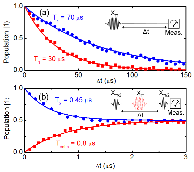
The energy relaxation of the state was measured by exciting the rhombi chain with a -pulse and then measuring its state after a variable time (see Fig.4a inset for pulse sequence). The results of the energy relaxation measurements at the optimal working point (, ) are presented in Fig.4a and Table 1. We also included in Table 1 the data for the device with a large degree of asymmetry (device 2). This asymmetry was caused by different values of the flux in the nominally identical rhombi: variations of the magnetic field across the chip were caused by conventional (slightly magnetic) microwave connectors on the sample holder. After replacing these connectors with the non-magnetic ones, this source of asymmetry was eliminated, and all the measured devices consistently demonstrated . The values of for the rhombi chains with a high degree of symmetry are 1-2 orders of magnitude greater than that for less symmetric rhombi circuits and unprotected Josephson qubits coupled to the same read-out circuit bell2012 ; bell2012a . The comparison shows that the symmetry protection supresses the decay rate by almost two orders of magnitude, in agreement with the large value of the decay suppression factor (Table 1). Note that the value of at might be limited by the Purcell decay into the resonator houck .
The quality factor for the protected rhombi chains exceeds (see Table 1), and is comparable with that for the state-of-the-art transmons coupled to 3D cavities paik2011 and TiN coplanar resonators chang2013 . However, the reasons for such a large in the transmon and in the rhombi chain are different. In the former case the decay is suppressed by the carefully designed microwave environment whereas in the latter case the rhombi symmetry prohibits the decay.
Table 1.
| Dev. | ||||||
|---|---|---|---|---|---|---|
| 1 | 0 | 6 | 64 | 20 | 1.1 | 30 |
| 1 | 0.5 | 2 | 7 | 20 | 0.9 | 70 |
| 2 | 0.5 | 4 | 3 | 1 | 0.03 | < 1 |
In contrast to the long decay time, the decoherence time in the studied devices was relatively short (). The time was determined in Ramsey measurements by applying an pulse followed by another pulse after a time t (see Fig.4b inset for pulse sequence). In the spin echo measurements, a refocusing pulse was applied between the two pulses. From the Ramsey and spin echo measurements we found and . The dephasing time is expected to be long if . In the studied chain, these energies were of the same order of magnitude, which resulted in significant dephasing (Fig.4b).
To conclude, we have demonstrated that a Josephson circuit can be symmetry-protected from the energy decay. We have studied the minimalistic protected circuit which contains two Josephson rhombi. The symmetry between the rhombus branches translates into the halving the periodicity of its Josephson energy , and allows only the simultaneous transfer of pairs of Cooper pairs on the central island mutual to both rhombi. The logical states of the protected qubit correspond to the even and odd number of Cooper pairs on this island. Our data indicate that the improved design of the Josephson rhombi doucot2012 reduces the sensitivity of the chain spectrum to the offset charge asymmetry. The measured phase and charge dependences of the energy of the transition are in good agreement with our numerical simulations. Symmetry protection results in a long energy relaxation time (up to 70) and a large quality factor of this qubit. The experiments provide a solid foundation for the next stage – the implementation of a qubit with much improved coherence due to a larger ratio which can be realized, e.g., by parallel connection of a few rhombi chains.
We would like to thank B. Doucot for helpful discussions. The work was supported in part by grants from the Templeton Foundation (40381), the NSF (DMR-1006265), and ARO (W911NF-13-1-0431).
References
- [1] Emanuel Knill. Quantum computing with realistically noisy devices. Nature, 434:39–44, 2005.
- [2] A.Yu. Kitaev. Fault-tolerant quantum computation by anyons. Annals of Physics, 303:2 – 30, 2003.
- [3] L.B. Ioffe, M.V. Feigelman, A. Ioselevich, D. Ivanov, M. Troyer, and G. Blatter. Topologically protected quantum bits using josephson junction arrays. Nature, 415:503–506, 2002.
- [4] L. B. Ioffe and M. V. Feigel’man. Possible realization of an ideal quantum computer in josephson junction array. Phys. Rev. B, 66:224503, 2002.
- [5] B. Doucot and J. Vidal. Pairing of cooper pairs in a fully frustrated josephson-junction chain. Phys. Rev. Lett., 88:227005, 2002.
- [6] B. Doucot, M.V. Feigelman, and L.B. Ioffe. Topological order in the insulating josephson junction array. Phys. Rev. Lett., 90:107003, 2003.
- [7] B. Doucot, M.V. Feigelman, L.B. Ioffe, and A.S. Ioselevich. Protected qubits and chern-simon theories in josephson junction arrays. Phys. Rev. B, 71:024505, 2005.
- [8] I.V. Protopopov and M.V. Feigelman. Anomalous periodicity of supercurrent in long frustrated josephson-junction rhombi chains. Phys. Rev. B, 70:184519, 2004.
- [9] I.V. Protopopov and M.V. Feigelman. Coherent transport in josephson-junction rhombi chain with quenched disorder. Phys. Rev. B, 74:064516, 2006.
- [10] P. Brooks, A. Kitaev, and J. Preskill. Protected gates for superconducting qubits. Physical Review A, 87:052306, 2013.
- [11] B. Doucot and L.B. Ioffe. Physical implementation of protected qubits. Rep. Prog. Phys., 75:1–20, 2012.
- [12] S. Gladchenko, D. Olaya, E. Dupont-Ferrier, B. Doucot, L.B. Ioffe, and M.E. Gershenson. Superconducting nanocircuits for topologically protected qubits. Nature Physics, 5:48–53, 2009.
- [13] I. M. Pop, K. Hasselbach, O. Buisson, W. Guichard, B. Pannetier, and I. Protopopov. Measurement of the current-phase relation in josephson junction rhombi chains. Phys. Rev. B, 78:104504, 2008.
- [14] I. M. Pop, B. Douçot, L. Ioffe, I. Protopopov, F. Lecocq, I. Matei, O. Buisson, and W. Guichard. Experimental demonstration of aharonov-casher interference in a josephson junction circuit. Phys. Rev. B, 85:094503, 2012.
- [15] Matthew T. Bell, Lev B. Ioffe, and Michael E. Gershenson. Microwave spectroscopy of a cooper-pair transistor coupled to a lumped-element resonator. Phys. Rev. B, 86:144512, 2012.
- [16] M.T. Bell, I.A. Sadovskyy, L.B. Ioffe, A.Yu. Kitaev, and M.E. Gershenson. Quantum superinductor with tunable non-linearity. Phys. Rev. Lett., 109:137003, 2012.
- [17] J. Aumentado, Mark W. Keller, John M. Martinis, and M. H. Devoret. Nonequilibrium quasiparticles and periodicity in single-cooper-pair transistors. Phys. Rev. Lett., 92:066802, 2004.
- [18] P.J. de Visser, J.J.A. Baselmans, P. Diener, S.J.C. Yates, A. Endo, and T.M. Klapwijk. Number fluctuations of sparse quasiparticles in a superconductor. Phys. Rev. Lett, 106:167004, 2011.
- [19] A. A. Houck, J. A. Schreier, B. R. Johnson, J. M. Chow, Jens Koch, J. M. Gambetta, D. I. Schuster, L. Frunzio, M. H. Devoret, S. M. Girvin, and R. J. Schoelkopf. Controlling the spontaneous emission of a superconducting transmon qubit. Phys. Rev. Lett., 101:080502, 2008.
- [20] Hanhee Paik, D.I. Schuster, L.S. Bishop, G. Kirchmair, G. Catelani, A.P. Sears, B.R. Johnson, M.J. Reagor, L. Frunzio, L.I. Glazman, S.M. Girvin, M.H. Devoret, and R.J. Schoelkopf. Observation of high coherence in josephson junction qubits measured in a three-dimensional circuit qed architecture. Physical Review Letters, 107:240501, 2011.
- [21] J.B. Chang, M.R. Vissers, A.D. Corcoles, M. Sandberg, J. Gao, D.W. Abraham, J.M. Chow, J.M. Gambetta, M.B. Rothwell, G.A. Keefe, M. Steffen, and D.P. Pappas. Improved superconducting qubit coherence using titanium nitride. Appl. Phys. Lett., 103:012602, 2013.
SUPPLEMENTARY MATERIALS
1. Estimate of the energy difference between protected states and the matrix element of perturbation.
In this section we give the details of the computation of the properties of the studied system which is equivalent to the discrete oscillator
| (3) |
We begin with the ideal system described by (3). Two lowest energy states of this problem correspond to wave functions that are non-zero on even or odd charges as explained in the main text. For brevity, we shall refer to these states as odd and even states. In the limit the splitting of the even and odd states can be found analytically. In this limit the wave functions in the phase representation are mostly localized near the minima of the first term in (3). Quantum transitions between two minima result in the coherent mixture of these two states with the bonding state corresponding to the even and antibonding state to the odd state in charge representation. To prove the correspondence between bonding and even states we notice that the bonding state does not change under transformation , while the antibonding state changes sign under this transformation. In the charge basis this implies that bonding state has only even components while antibonding - only odd ones. In the quasiclassical approximation the amplitude of this transition in which the phase slips by is
| (4) |
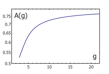
Here , is the plasma frequency, the dimensionless parameter has a physical meaning of the extent of the wave function in the charge representation: . In the asymptotic limit of very large the prefactor in (4), but for moderately large is significantly different from its asymptotic value as shown in Fig. S5.
The phase slip transitions by lead to the same states. Adding these amplitudes we get that gives energy splitting between odd and even states
| (5) |
We now discuss the effect of perturbations. Small but non-zero term in the Hamiltonian leads to the transition between odd and even states. In the limit of large the amplitude of this transition is so in the basis of odd and even states the Hamiltonian becomes
that gives energy splitting between ground and the first excited state
| (6) |
We now discuss the effect of external noises. The largest source of noise is produced by fluctuating potentials that are coupled to the charge operator. Another smaller but potentially dangerous source of noise are fluctuations of cause by flux fluctuations in each rhombus: where is the Josephson energy of the small Josephson junction. These noises are described by the Hamiltonian
In the charge basis the operator is diagonal, so it remains diagonal in the basis of even and odd states. At the wave functions of these states are symmetric in , so the potential fluctuations are decoupled in the linear order at . For the diagonal matix elements of can be found by differetiation of :
It contains the same exponential factor as the energy splitting. In the absence of the external potential leads only to the dephasing proportional to . For instance, the Johnson noise associated with the effective impedance of the central island leads to dephasing rate
| (7) | |||||
Here is the quantum of resistance and is the typical frequency responsible for dephasing process, for realistic temperatures so This equation assumes slow frequency dependence of the in a relevant frequency range . Small results also in a decay:
The effect of the flux fluctuations is more direct because they affect the energy difference between the levels (6). Assuming that flux noise is characterized by the spectrum with infrared cutoff that translates into the spectrum of fluctuations
Here is the typical scale of fluctuations caused by low frequency noise, it is related to the typical flux variations by where is the Josephson energy of the small contact in individual rhombus. The numerical coefficient in this equation is of the order of unity in the regime (, similarly to it decreases at .
2. Measurement setup and procedures.
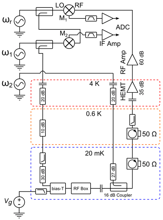
The main elements of the MW set-up are shown in Fig. S2. The microwave response of the Josephson rhombi chain coupled to the read-out resonator (see Fig. 2) was probed by measuring both the phase and amplitude of the microwaves traveling along a microstrip feedline coupled to the resonators. This setup enabled the testing of several devices fabricated on the same chip in a single cooldown.
The microwaves at the probe frequency , generated by a microwave synthesizer, were coupled to the cryostat input line through a 16 dB coupler and transmitted through the microstrip line coupled to the resonators. The cold attenuators and low-pass filters in the input microwave lines prevent leakage of thermal radiation into the resonator. On the output line, two cryogenic Pamtech isolators ( dB isolation between 3 and 10 GHz) anchored to the mixing chamber attenuate the 5 K noise from the cryogenic HEMT amplifier (Caltech CITCRYO 1-12, 35 dB gain between 1 and 12 GHz). The amplified signal is mixed by mixer M1 with the local oscillator signal at frequency , generated by another synthesizer. The intermediate-frequency signal at is digitized by a 1 GS/s digitizing card (AlazarTech ATS9870). The signal is digitally multiplied by and , averaged over an integer number of periods, and its amplitude (proportional to the microwave amplitude ) and phase is extracted as and , respectively. The reference phase (which randomly changes when both and are varied in measurements) is found using similar processing of the low-noise signal provided by mixer M2 and digitized by the second channel of the ADC. This setup enables accurate measurements of small changes unaffected by the phase jitter between the two synthesizers. The low noise of this setup allowed us to perform measurements at a microwave excitation level of -133 dBm which corresponded to a sub-single-photon population of the tank circuit. In the second-tone measurements, the tested rhombi chain was excited by the microwaves at frequency coupled to the transmission line via a 16 dB coupler.
In the presence of charge fluctuation on the central island of the chain, we have applied a sweep-by-sweep averaging method. Since these fluctuations are slow (on the time scale of seconds), we perform 10-100 full-range sweeps of the second tone frequency (at a rate of 10ms per one value of ) and then perform averaging of the completed sweeps rather than a point-by-point averaging of the second tone sweep.
The sample was mounted inside an rf-tight copper box that provided the ground plane for the microstrip line and resonator. This box was placed inside another rf-tight copper box in order to eliminate any stray infrared photons. This nested-box construction was housed inside a cryogenic magnetic shield (A4k), followed by a superconducting aluminum magnetic shield. All the connectors inside the magnetic shields were non-magnetic (EZForm); this reduces the stray magnetic field at the sample location down to 0.1 mGauss. The entire sample and shielding construction was anchored to the mixing chamber of a cryogen-free dilution refrigerator with a base temperature of 20 mK.
In order to control the charge on the central island of the chain, a DC gate voltage was applied to the microstrip line via a bias-T. External noises at the DC port of the bias-T were attenuated with a voltage divider and a series of low-pass filters and stainless steel powder filters.
3. The probe-tone measurements
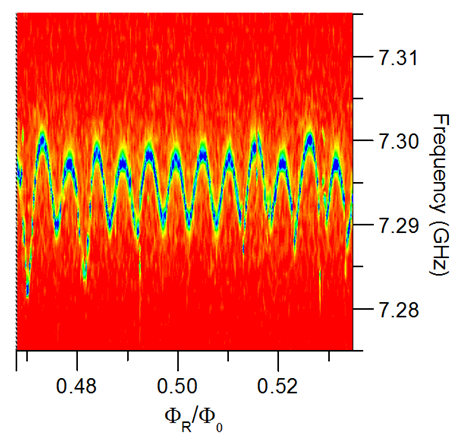
The oscillations in the resonance frequency versus the magnetic flux are shown in Fig. S3 near zero magnetic field (a) and full frustration (b). The oscillations in the resonance frequency reflect the dependence of the inductance of the chain in its ground state as a function of the phase across the chain, . Near full frustration, the period of oscillations corresponds to . The range of fluxes where the -periodicity was observed agrees well with the theory. The dependence also demonstrates avoided crossings observed when the resonance frequency coincides with the resonance in the read-out resonator (the “spikes” in Fig. S3b), but the second-tone measurements discussed in the main text provide much more detailed information on the chain spectrum.

The energy can be estimated from the measurements of the probe-tone microwave amplitude versus the magnetic flux (Fig. S3). The energy is inversely proportional to the Josephson inductance of the chain: . Both quantities depend on the phase across the chain - , - so and when . Using the equivalent circuit in Fig. 2c, one can estimate from the swing of the resonance frequency of the resonator coupled to the chain (MHz in Fig. S2b). Using and , we estimate , which translates into (or GHz). This estimate agrees very well with the fitting parameters used to simulate the chain spectrum.
4. Spectroscopic data at and