Enhanced propagation of photon density waves in random amplifying media
Abstract
We demonstrate enhanced wave-like character of diffuse photon density waves (DPDW) in an amplifying random medium. The amplifying nature makes it contingent to choose the wave solution that grows inside the amplifying medium, and has a propagation vector pointing opposite to the growth direction. This results in negative refraction of the DPDW at an absorbing-amplifying random medium interface as well as the possibility of supporting “anti”-surface-like modes at the interface. A slab of amplifying random medium sandwiched between two absorbing random media supports waveguide resonances that can be utilized to extend the imaging capabilities of DPDW.
pacs:
(170.5270) Medical optics and biotechnology, Photon density waves; (110.0113) Imaging systems, Imaging through turbid media; (290.1990) Scattering ,Diffusion; (110.7050) Imaging systems, Turbid media.It is well known that a time-modulated light source placed in a random scattering medium creates a modulation in the density of the diffuse photon flux yodh1 . These density variations propagate in the source free regions of the random medium according to the diffusion equation
| (1) |
where, is the diffusion coefficient, with being the reduced scattering coefficient, is the absorption coefficient, is the amplitude of the density variation and is the speed of light in the medium in which the scatterers are embedded. The waves have been popularly known as Diffuse Photon Density Waves (DPDW) in the area of biomedical imaging where it has been used for a variety of imaging through biological media yodh ; durduran . These waves are known to exhibit interference inter and diffraction boasdiff , and can be related across interfaces between two distinct scattering media by reflection and transmission coefficients yodh1 ; ripoll . DPDW suffer from strong attenuation due to scattering and typically have penetration depths of only a couple of centimeters at MHz modulation frequencies.
The diffusion approximation itself breaks down at much higher modulation frequencies harsha_su_grobe . We note that other theories for photon migration weiss ; sar have been shown to be advantageous in the short time limits (large modulation frequencies). However, the diffusion equation 1 describes the DPDW well in the steady state at length scale much larger than the transport mean free path for reasonable modulation frequencies ( MHz) yodh1 ; yodh . Another limitation for the DPDW intensity arises from the intrinsic absorption in the medium. Amplification of light has been used to compensate for attenuation of the waves in many contexts, for example, fiber amplifiers edfa-book , amplifying media in metamaterials/perfect lenses of negative refractive index zeludev ; sar1 , extending surface plasmon propagation lengths at the interface of metal/amplifying medium grafstrom . Random amplifying media are well known in the context of random lasers cao_iop . The compensation of absorption by laser gain in random media is known to lead to the sharpening of the coherent backscattering peak and increased weak localization wiersma .
In this letter, we examine the behaviour of DPDW in an amplifying random medium. The incorporation of gain in the random medium results in extending the wavelike characteristics of the DPDW, wherein the real part of the wavevector can become larger than the imaginary part. For an incident DPDW at an interface of absorbing-amplifying media, we find that negative refraction of the DPDW can occur. This results from a physical choice of the wavevector that is mandated by the requirement of a growing density wave inside the amplifying random medium in spite of the DPDW having a positive phase velocity in both the media. Although the finite modulation frequency of the DPDW renders the waves exponentially decaying, a slab of amplifying random medium can support resonant waveguide modes.
Assuming plane wave solutions of the form, , for the diffusion equation results in the following dispersion relation
| (2) |
In order to obtain the wave-vector , we are faced with the classic problem of choosing the sign of the square root sar_om_OL_2005 from the dispersion relation in Eqn. 2, which yields
| (3) |
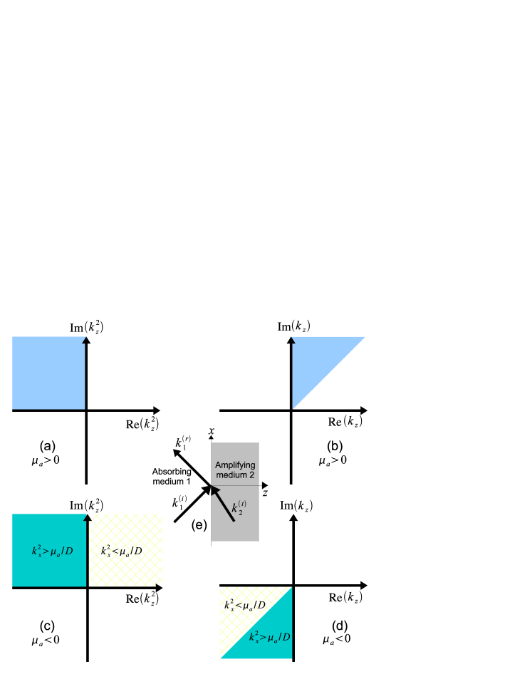
Note that the coefficient () can either be positive (for absorption) or negative (for amplification). The validity of the diffusion equation to describe photon migration is contingent on the magnitude , whereby scattering dominates over absorption/amplification. The level of amplification of the diffuse flux due to establishes the threshold for lasing in random lasers cao_iop or criticality in nuclear reactors. The imaginary part of the wave-vector arises principally due to the non-zero frequency of modulation. The correct physical procedure to fix the sign lies in studying the wave in a dissipative random medium and choosing a wave-vector that causes decay of the wave with increasing distance of propagation . For the time being, we focus our attention on the complex number in Eqn.(3). We note that lies in the second quadrant of the complex plane and hence in the absorbing medium will lie in the first quadrant (see Fig. 1). This gives rise to the usual DPDW that exponentially decays with distance due to an imaginary part of that is larger than the real part of , thereby limiting the wavelike character.

We now turn our attention to an amplifying random medium. In this case, lies in the first quadrant of the complex plane and could lie either in the first quadrant or in the third quadrant. Due to amplification, the amplitude of the diffuse photon flux will increase exponentially with increasing distance of propagation under conditions of linear unsaturated gain. Hence, we require the wavevector to have a negative imaginary part for a physical solution, and will lie in the third quadrant as shown in Fig. 1 ( for our discussion here). Note, that regardless of the choice of the sign of , the is always greater than the for the random amplifying medium. This implies that the oscillatory aspect of the DPDW is enhanced over the exponential decay arising intrinsically from multiple scattering, which also contributes to amplification owing to the resulting longer path through the gain medium. A discussion of the relevant physical length and frequency scales is imperative at this juncture: the amplifying medium provides unbiased amplification of both the background diffuse flux as well as the flux associated with the DPDW, as these two fluxes cannot be distinguished by the stimulated emission process. The modulation frequency (typically to MHz) responsible for the DPDW is much smaller compared to the bandwidth of the gain medium ( THz for typical dye molecules). The gain can be considered uniform as the diffusion length scales are much shorter than the wavelength of the DPDW.
Now let us understand the solutions with our requirement for for the random amplifying medium which involves a negative real part of the wave-vector. The oscillatory flux associated with the DPDW given by , points in the same direction as the real part of the wavevector. The complex nature of the the arises due to the complex phasor notation for the PDW used in the paper. The real and imaginary parts should simply be viewed as representing the in-phase and in-quadrature components of the response in relation to the oscillatory source term. We have a wave with positive phase velocity where both the wavevector and the flux vector point in the same direction. Both these consequences are dictated by the need for having the DPDW amplitude as well as the background diffuse flux that exponentially increase with distance from a source in a gain medium. This solution should be compared with solutions pertaining to the electromagnetic waves in the negative refractive index media sar_book . A negative choice of the wavevector (real part) is required in that context also. However, the Poynting vector representing the energy flux associated with the electromagnetic wave is oppositely oriented to the wavevector, which is an intrinsic character of a wave with negative phase velocity. Note that these differences principally arise from the governing equations: the Maxwell’s equations for the electromagnetic waves and the diffusion equation for the DPDW.

Consider the refraction of the DPDW at an interface between an absorbing random medium and an amplifying random medium when the DPDW is incident from the absorbing side. Without loss of generality, we choose the plane to be the interface and invariance along the direction, so that the incident wavevector lies in the plane such that (see Fig. 1e). Continuity of the interface in the direction implies equality of in both the media. The normal component is given by
| (4) |
with the choice of sign in the two media governed by the previous discussion. The evidence of negative refraction at the interface lies in the decrease of the phase of the DPDW with increasing distance from the interface into the amplifying medium. Ensuring the conditions of continuity of the amplitude of the DPDW and the normal component of the flux yields
| (5) |
where the subscripts I,R and T refer to the incident, reflected and the transmitted DPDW at the interface, respectively. The reflection and transmission coefficients are given by
| (6) |
Ripoll and Nieto-Vesperinas ripoll have shown the existence of a Brewster-like condition, where the reflection coefficient () goes to zero, for a DPDW with (the static limit). This condition can be thought of as arising from matching of the absorption length in the two media with an appropriately factored periodicity of the photon density wave along the propagation direction . This impedance matching occurs at at which , see Fig. 2(a), which in turn is determined by the various parameters of the medium, where
| (7) |
For the imaginary part is negligible and a proper choice of and allows one to tailor its occurrence and this can be used to realize a directional filter ripoll .
It appears intriguing that a pair of rather isotropic random media should choose a specific for an efficient coupling of the DPDW. The conventional Brewster angle observed for electromagnetic waves reflected across interfaces is a polarization dependent feature that arises from the requirement of orthogonality of the induced material polarization to the reflected direction. What would then underly the Brewster-like condition of the scalar density waves? The above Eqn.(7) indicates that it is the matching of the absorption length across the two media that is more fundamental, and hence the difference between the at the interface of these media is augmented by the component of the DPDW. Here, , and the absorption length is the (rms) average distance between begin and end points of paths of length in the random medium. Thus, the reflection minimum leading to strong coupling occurs such that the wave propagation dictated by the periodicity of the is matched with the difference of the absorption lengths in the two media.
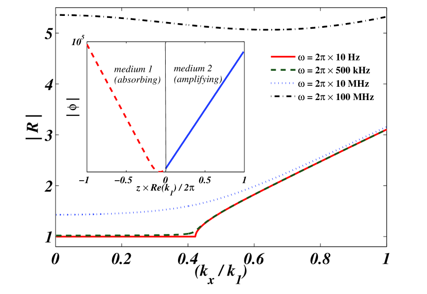
In the case of the absorbing-amplifying media interface, the above situation simply does not exist. The sign of changes, and the expressions of and Eqn.(6) transform appropriately, leaving behind a denominator that is positive definite because of the reversal of the sign of of the amplifying medium foot . For one obtains at normal incidence as well as for . At , the real part of becomes zero and beyond this point the reflection coefficient continues to increase as the input angle is increased due to the dominance of the imaginary part of the wavevector (Fig. 1d). Note again that the pertinent length scale is the amplification length ( defined similarly to the above) which determines the condition on the different regimes of . In Fig. 2(b) we present reflection and transmission coefficients at an interface of an absorbing-amplifying medium for various modulation frequencies.
One can also arrange to obtain an “anti”-surface mode at an absorbing-amplifying interface having a minima at the interface and the field growing with distance on both sides of the interface (see inset in Fig.2b). These fields do not correspond to a true surface mode as the DPDW diverges at infinity, and hence cannot exist in isolation without the exciting input density wave. Such a mode has been envisaged in the context of impedance matched perfect lenses made of a negative refractive index material pendry-sar . This physical realization can occur only in conjunction with an amplifying medium and an absorbing-absorbing interface cannot support such a mode.
We present the response of a slab of amplifying random medium sandwiched between identical absorbing random media, with the reflection and transmission given as
| (8) | |||||
| (9) |
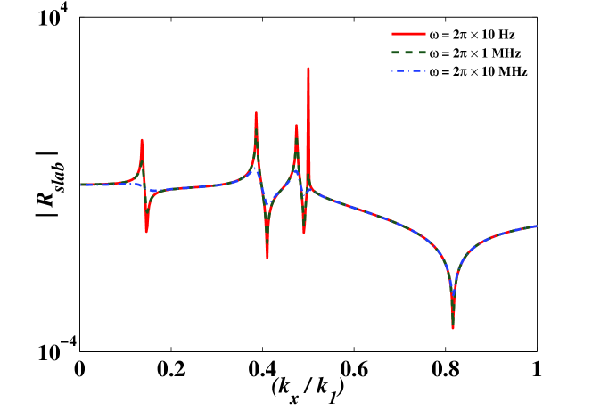
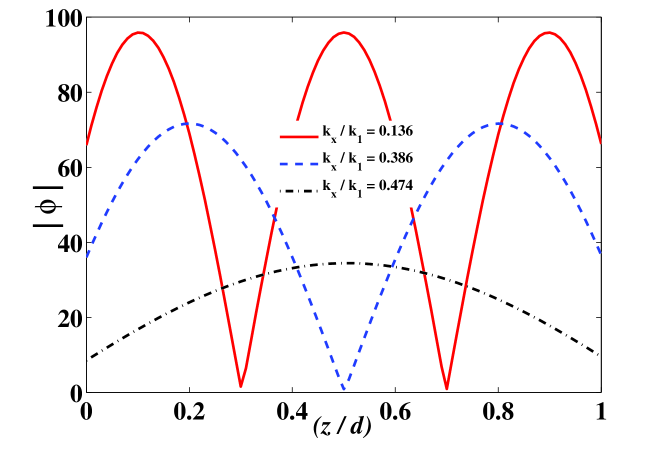
where, is the thickness of the slab and . The above expressions for a finite slab are invariant with respect to the sign of axl4 . The reflection and transmission as a function of show large peaks at the resonant conditions for an amplifying slab as in Fig. 3. Such a configuration leads to localized waveguide modes within the amplifying slab. The density variation with distance inside the slab is shown in Fig. 3(c). The integral half-wavelength-like conditions are apparent. We have chosen the parameters in Fig.3 such that and hence for the field in the slab is evanescent. Due to this, the transmission does not contain resonant features for . The ability of a layer of amplifying random medium to guide DPDW can be exploited in imaging situations, wherein coupling to the random medium and extraction of the DPDW can be greatly enhanced.
In conclusion, we have demonstrated that incorporating amplification (laser gain) in a random medium can substantially enhance the wavelike characteristics of the DPDW. This aspect may be used for increasing the depth over which imaging can be carried out in a random medium with DPDW. The physical requirement of a growing density wave in an amplifying random medium results in a backward flux towards the interface with the absorptive random medium. This gives rise to negative refraction across the interface and conditions can result to produce “anti”-surface like states at such interfaces. A slab of amplifying random medium is shown to waveguide DPDW and we suggest that such waveguides can be used for improving the imaging capabilities of the DPDW, whose non-invasive aspects continue to hold great promise in diagnostic imaging.
We thank S. Guenneau for initial discussions on possibility of negative refraction in diffusive systems.
References
- (1) M.A. O’Leary, A.G. Yodh and B. Chance, Phys. Rev. Lett. 69, 2658 (1992).
- (2) A.G. Yodh and B. Chance, Phys. Today, 48, 34 (1995).
- (3) T. Durduran, R Choe, W. B. Baker and A. G. Yodh, Rep. Prog. Phys. 73, 076701 (2010).
- (4) J. M. Schmitt, A. Kn ttel, and J. R. Knutson, J. Opt. Soc. Am. A, 9, 1832-1843 (1992).
- (5) D.A. Boas, M.A. O’Leary, B. Chance and A.G. Yodh, Phys. Rev. E, 47, R2999 (1993)
- (6) J.Ripoll and M. Nieto-Vesperinas, Opt. Lett., 24, 796-798 (1999)
- (7) Q. C. Su, G.H. Rutherford, W. Harshawardhan, R Grobe Laser Phys. 11, 94-101 (2001).
- (8) M.Porr‘a, J. Masoliver and G. H.Weiss, Phys. Rev. E 55 7771 (1997).
- (9) S. A. Ramakrishna and N. Kumar, Phys. Rev. E 60, 1381 (1999).
- (10) E. Desurvire, D. Bayart, B. Desthieux, and S. Bigo, “Erbium-doped fiber amplifiers: Device and System Developments. ” Vol. 2. (Wiley-Interscience, 2002).
- (11) E. Plum, V. A. Fedotov, P. Kuo, D. P. Tsai, and N. I. Zheludev, Opt. Express, 17, 8548 (2009).
- (12) S. A. Ramakrishna and J.B. Pendry, Phys. Rev. B 67 201101(R) (2003)
- (13) J. Seidel, S. Grafstrom, and L. Eng, Phys. Rev. Lett. 94 177401 (2005).
- (14) H. Cao, Waves in Random Media 13, R1-R39 (2003)
- (15) D. S. Wiersma, M. P. van Albada, and A. Lagendijk Phys. Rev. Lett. 75, 1739-1742 (1995).
- (16) J. Andreasen, A. A. Asatryan, L. C. Botten, M. A. Byrne, H. Cao, L. Ge, L. Labont , P. Sebbah, A. D. Stone, H. E. T reci, and C. Vanneste, Advances in Optics and Photonics 3, 88-127 (2011)
- (17) R. C. Polson and Z. V. Vardeny, Appl. Phys. Lett. Vol. 85, No. 7 (2004)
- (18) S.A. Ramakrishna and Oliver J.F. Martin, Opt. Lett. 30, 2626 (2005).
- (19) S. A. Ramakrishna and T.M. Grzegorczyk, “Physics and Applications of Negative Refractive Index Materials”, (CRC Press and SPIE Press, 2008).
- (20) Contrast this with for the absorbing-absorbing media interface where the numerator of goes through a zero for leading to the Brewster-like condition.
- (21) J.B. Pendry and S. A. Ramakrishna, Physica B (Conden. Matt.) 338, 329-339 (2003)
- (22) A. Lakhtakia, J. B. Geddes III, and T. G. Mackay, Opt. Express, 15, 17709-17714 (2007)
References
- (1) M.A. O’ Leary, D.A. Boas, B. Chance and A.G. Yodh, “Refraction of Diffuse Photon Density Waves ”, Phys. Rev. Lett Vol. 69, 2658 (1992)
- (2) Arjun Yodh and Britton Chance, “Spectroscopy and Imaging with Diffusing Light”. Phys. Today, 48, 34 (1995).
- (3) T. Durduran, R Choe, W. B. Baker and A. G. Yodh, “Diffuse optics for tissue monitoring and tomography”. Rep. Prog. Phys. 73, 076701 (2010).
- (4) J. M. Schmitt, A. Kn ttel, and J. R. Knutson, “Interference of diffusive light waves,”. J. Opt. Soc. Am. A, 9, 1832-1843 (1992).
- (5) D.A. Boas, M.A. O’Leary, B. Chance and A.G. Yodh, “Scattering and wavelength transduction of diffuse photon density waves ”, Phys. Rev. E, 47, R2999 (1993)
- (6) J.Ripoll and M. Nieto-Vesperinas, “Reflection and transmission coefficients for diffuse photon density waves. ”Opt. Lett., 24, 796-798 (1999)
- (7) Q. C. Su, G.H. Rutherford, W. Harshawardhan, R Grobe “Non-diffusive behavior of laser beams in a highly scattering medium”Laser Phys. 11, 94-101 (2001).
- (8) M.Porr‘a, Jaume Masoliver and George H.Weiss, “When the telegrapher s equation furnishes a better approximation to the transport equation than the diffusion equation”Phys. Rev. E 55 7771-7774 (1997).
- (9) S. A. Ramakrishna and N. Kumar, “Diffusion of particles moving with constant speed”Phys. Rev. E 60, 1381 (1999).
- (10) E. Desurvire, D. Bayart, B. Desthieux, and S. Bigo, “Erbium-doped fiber amplifiers: Device and System Developments. ” Vol. 2. (Wiley-Interscience, 2002).
- (11) E. Plum, V. A. Fedotov, P. Kuo, D. P. Tsai, and N. I. Zheludev, “Towards the lasing spaser: controlling metamaterial optical response with semiconductor quantum dots ”Opt. Express, 17, 8548 (2009).
- (12) S. A. Ramakrishna and J.B. Pendry, “Optical gain removes absorption and improves resolution in a near-field lens”, Phys. Rev. B 67 201101(R) (2003)
- (13) J. Seidel, S. Grafstrom, and L. Eng, “Stimulated emission of surface plasmons at the interface between a silver film and an optically pumped dye solution,”Phys. Rev. Lett. 94 177401 (2005).
- (14) Hui Cao, “Lasing in random media”, Waves in Random Media 13, R1-R39 (2003)
- (15) D. S. Wiersma, M. P. van Albada, and A. Lagendijk “Coherent backscattering of light from an amplifying medium”, Phys. Rev. Lett. 75, 1739-1742 (1995).
- (16) J. Andreasen, A. A. Asatryan, L. C. Botten, M. A. Byrne, H. Cao, L. Ge, L. Labont , P. Sebbah, A. D. Stone, H. E. T reci, and C. Vanneste, “Modes of Random Lasers”, Advances in Optics and Photonics 3, 88-127 (2011)
- (17) Randal C. Polson and Z. Valy Vardeny, “Random lasing in human tissues”, Appl. Phys. Lett. Vol. 85, No. 7 (2004)
- (18) S.A. Ramakrishna and Oliver J.F. Martin, “Choice of the wave-vector in negative refractive media: The sign of ”, Opt. Lett. 30, 2626 (2005).
- (19) S. A. Ramakrishna and T.M. Grzegorczyk, “Physics and Applications of Negative Refractive Index Materials”, (CRC Press and SPIE Press, 2008).
- (20) Contrast this with for the absorbing-absorbing media interface where the numerator of goes through a zero for leading to the Brewster-like condition.
- (21) J.B. Pendry and S. A. Ramakrishna, “Refining the perfect lens ”Physica B (Conden. Matt.) 338, 329-339 (2003)
- (22) Akhlesh Lakhtakia, Joseph B. Geddes III, and Tom G. Mackay, “When does the choice of the refractive index of a linear, homogeneous, isotropic, active, dielectric medium matter?”Opt. Express, 15, 17709-17714 (2007)