Coherent emission of quanta by synchrotron radiation excited nuclei: geometry of nearly backward scattering
Abstract
A possibility of further development of Synchrotron Mössbauer Source (SMS) of 57Fe 14.4 keV radiation is considered. The principles and detailed description of the SMS device is given in Refs. [Sm2011, ; JSR, ]. The perfect crystal of Iron Borate, FeBO3, is the central element of this device. The coherent nuclear fluorescence of IB crystal illuminated by synchrotron radiation produces the sharply directed beam of 14.4 keV Mössbauer radiation from the crystal set at the pure nuclear Bragg reflection. Up to now the low angle scattering geometry was used for generation of the coherent radiation. The analysis performed in the present paper shows that the source of about two times larger power can be obtained when nearly backward scattering geometry is employed. This result can be efficiently applied in development of high resolution spectroscopy using synchrotron radiation.
pacs:
61.10.Eq, 76.80.+y, 42.25.HzI Introduction
Backward coherent scattering of x-rays and neutrons is a well known technique of high-resolution x-ray and neutron spectroscopy. General dynamical effects in resonant backward coherent scattering of Mössabuer radiation were studied in Ref. [vB1988, ]. New interest in nuclear resonant back-reflection arose in connection with generation of the coherent radiation with the help of synchrotron radiation (SR). The particular case of the coherent emission of -ray photons by synchrotron-radiation-excited 57Fe nuclei in FeB03 crystal was studied in Refs. [Sm2011, ; Pot2012, ]. General properties of nuclear resonant diffraction are well revealed in this case. During free de-excitation of the nuclei, a nuclear exciton polariton is developing inside the crystal and generates at the exit of the crystal a coherent -ray beam. The lifetime of nuclear exciton polariton is of the order or somewhat less than natural lifetime of the nuclear excited level. In the case of 57Fe nuclei it is about s. In the conditions of stationary illumination of the crystal by SR a permanent intensity beam of radiation is generated.
Up to now the coherent emission of radiation was studied in the low angle scattering geometry [Pot2012, ; Sm1997, ; Sm2000, ; Mitsu2009, ]. Considerable interest in back-reflections arises due to beneficial applications of this type reflections in -ray optics. There are several reasons for that. The use of pure nuclear back-reflections with high reflectivity in an angular range of 100-200 expected for back reflections would allow much more Mössbauer radiation to be generated by the synchrotron beam. The necessary condition for high reflectivity is the fact that the form factor of the amplitude of nuclear resonant scattering equals unity in the whole angular range. This is because a nucleus size is much less than the wave length of radiation involved. The reflectivity in back diffraction can be essentially enlarged by employing so called asymmetric reflections for which the reflecting planes are inclined with respect to the plane of crystalline surface. Beside that more freedom is opened to play with the polarization factor of nuclear amplitude to increase it.
Strong nuclear reflections exactly in backward direction might also be applied in the resonator systems of Fabry-Perrot type. Finally, the practical advantage of the back reflection is the possibility of using much more simple driving system. To provide energy modulation the crystal should be mounted on a Mössbauer transducer. At the same time diffraction conditions must be fulfilled. To allow for diffraction in a low angle scattering geometry, the crystal is to be attached to the moving frame above the transducer, Fig. 6 in Ref. [JSR, ]. Therefore special care is needed to balance the frame. When scattering occurs in back direction the diffracting crystal can be mounted directly on the transducer rod.
Based on the above consideration, aim of the present paper is to investigate the rays coherent emission function in the geometry of backward scattering from nuclear array. We first present solutions for the Fourier component of electric field in the wave scattered by nuclear array in the vicinity of nuclear resonance and of Bragg angle. After that angular functions of the coherent emission and spectral composition of the emitted radiation are calculated for a particular case of the nearly backward reflection.
II Elements of dynamical theory of nuclear resonant diffraction
A nuclear array in a crystal represents for Mössbauer radiation a resonating three-dimensional grating, which gives rise to resonant Bragg diffraction of -rays. If regularity of the grating persists over a large volume of the crystal, the multiple scattering of radiation occurs. Mutual interference of the propagating and Bragg reflected waves produces a resultant wave field the structure of which is of a standing-wave type. In this way the standing-wave mode of nuclear exciton polariton is realized under conditions of Bragg diffraction. At the exit of the crystal a coherent beam of resonant radiation is formed. In general, the Bragg diffraction in large perfect crystals is described by the dynamical theory accounting for the multiple scattering of radiation by atoms. A detailed account of the dynamical diffraction theory of nuclear resonant diffraction is given by Kagan, Trammell, and Hannon [Ka1999, ; HanTram1999, ]. We shortly summarize the theory based on the solution of the Maxwell equations and apply it to our case. For a space and time Fourier component of the electric-field vector , which represents the amplitude of a plane monochromatic -ray wave having the wave vector and frequency , the Maxwell wave equation can be written in the following form
| (1) |
where , is the light velocity in vacuum, is the Fourier component of the induced current density. It has contributions from both the electric and nuclear subsystems. But our interest is focused on the pure nuclear reflections. In this case the interference field is created only by nuclear currents and the above equation is in fact the equation for a space time Fourier component of nuclear polariton where the radiation field and nuclear excitation are coupled. The induced nuclear current density represents a quantum mechanical average over the nuclear ensemble. In the linear in field approximation the excited nuclear current is proportional to the electric field , where is the nuclear susceptibility amplitude. Employing this relationship one can arrive at the Maxwell equation for the field amplitude only. We shall consider the case of the two-waves diffraction. In this case the two coherent waves are built up in the crystal, one propagating in the direction of incident wave, the other in the direction of the diffracted wave. The Maxwell wave equation splits then into a set of the two equations
| (2) |
where are the scalar electric field amplitudes for a definite wave polarization and propagation direction ; when the basic polarizations of radiation, and , are involved and for the forward and Bragg scattered waves respectively; and are the complex wave numbers describing the coherent waves inside the crystal , are the nuclear susceptibility amplitudes (radiation frequency , the incident photon energy), the amplitudes labeled by tilde include the small additions of the electronic susceptibility amplitude, , , , that is actual for the straightforward scattering. The complex wave numbers differ from the absolute value of the wave vector in vacuum by only small complex corrections
| (3) |
In the vicinity of Bragg angle , where is the angular parameter proportional to deviation from Bragg angle and is asymmetry parameter, , where are the angles between the inward normal to the crystalline entrance surface and the wave vectors respectively. The value is called in the dynamical theory as Lorentz factor. With the account of the relations Eq. (3) we arrive at the following equations set (neglecting the small order values)
| (4) |
where polarization indexes are omitted. The set of homogeneous equations (4) have a solution for the scalar field amplitudes only if the determinant formed by their coefficients turns to zero
| (5) |
Eq. (5) determines the dispersion of the electromagnetic waves in the crystal, giving the complex value as a function of the radiation frequency and of the angular deviation from the exact Bragg position. There are two roots of the Eq. (5)
| (6) |
Correspondingly the set of two equations Eq. (4) transforms into a set of four equations. We write down now the set of four linear equations first for the waves propagating in the primary direction
| (7) |
and then for those propagating in the scattering direction
| (8) |
Since the equations are homogeneous in order to find solutions for the scalar amplitudes one has to attract additional relationships between the fields. These are given by the boundary conditions. The solutions for the scalar field amplitude can be written in the following way. For the constituent field, which propagates in the primary direction as
| (9) |
and for that propagating in the direction of the Bragg reflection as
| (10) |
where the common phase factors are omitted, is the depth in the crystal, at the entrance to the crystal .
At the entrance boundary the diffracted wave is not yet built up, therefore the scalar amplitude of the incident field must be equal to the sum of scalar amplitudes of the waves propagating in the forward direction
| (11) |
The boundary condition for the field at the exit surface is based on the consideration, that the sum of amplitudes of the waves propagating in Bragg direction must be equal zero, because below this boundary there is no scattering matter
| (12) |
where is the thickness of the crystalline platelet, therefore is the path length for the radiation beam from the entrance to the exit surfaces, it is here assumed that Solution of the Eqs. (7,8) for the scalar amplitudes of the electric field with the account for the boundary conditions Eqs. (11,12) yields for the refraction index
| (13) |
and correspondingly for the refraction index
| (14) |
The two pairs of the scalar amplitudes corresponding to a particular dispersion correction or are found. Each field is a function of angular and frequency parameters - . The amplitude is in our case the scalar amplitude of the synchrotron radiation with as the intensity of synchrotron radiation within the frequency range selected by the monochromator system. This is a specific feature of nuclear resonant Bragg reflection that the coherent emission from a crystal containing nuclear array exhibits a combined angular and energy dependence.
One may consider the two solutions for the interference wavefield: WF1- and WF2 - presenting standing waves with amplitudes modulated along the normal to the scattering planes.
The signs at the square root in the Eq. (6) for are taken to have Then the exponential factor and in the limit of thick crystal and small angles of incidence the denominators of the expressions in the Eq. (13) for increase infinitely, so that the contribution from these field components vanishes. On the contrary, since the parts with exponentials in the denominators of disappear and in the limit we obtain
| (15) |
Only one wavefield survives in the semi-infinite crystal. In the following section we shall apply the general solutions given by the Eqs. (11,12) to calculate the angular and spectral properties of radiation emitted by the synchrotron radiation excited nuclei in FeB03 crystal in the geometry of a nearly backward scattering.
III Backward scattering geometry
Now we shall try to formulate conditions for reaching as high as possible coherent response of nuclear array excited by synchrotron radiation. We shall rely on Eq. (15) to find the amplitude of the reflected radiation near the Bragg angle in the nuclear resonance range. When the crystal is set at the angle the expression for Eq. (6) takes the form
| (16) |
To get the largest strength of nuclear system response one should select those reflections for which the suppression of the incoherent channels, i.e. the cancellation of the total amplitude for the individual nuclear excitation (the Kagan-Afanas’ev rule) is satisfied, see Refs. [Ka1999, ; Sm1988, ]. When the Kagan-Afanas’ev rule is fulfilled, the following relation between the matrix elements of nuclear susceptibility is valid . If this necessary condition is met turns to zero and the expression for the field amplitude reduces to
| (17) |
Making use this expression one can characterize the properties of strong reflection. First of all one can see that the field amplitude is proportional to the asymmetry factor . In the symmetric Bragg geometry (for definition of see text after Eq. (3)). Obviously, in the conditions of a low angle diffraction this factor can not be essentially enlarged, while the geometry of back diffraction can suggest such a possibility. The next factor of proportionality is the nuclear susceptibility . As it was shown in Ref. [Sm1980, ] the nuclear susceptibility in the case of pure nuclear diffraction in FeBO3 is proportional to or depending on what polarization has the incident radiation or , where is inclination angle of the reflecting planes to the crystalline surface. The FeBO3 crystals, as grown, usually have the form of plane parallel platelets with the entrance and exit surfaces parallel to the crystalline planes (1 1 1). For such crystals the best candidate for strong nuclear resonant scattering of synchrotron radiation is nearly back reflection (3 3 11). It is characterized by Bragg angle , i.e., the scattering angle in this case is . This reflection was studied earlier in Ref. [vB1988, ]. The chosen crystalline planes (3 3 11) are inclined at an angle of to the surface of the crystalline platelet. The scattering scheme is shown in Fig. 1.
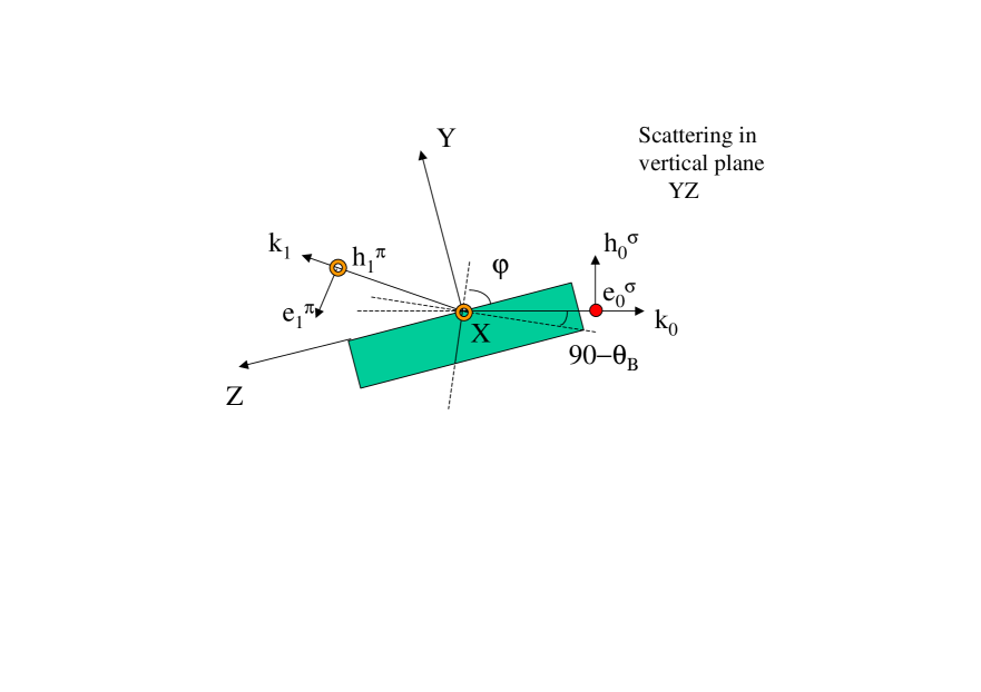
The asymmetry factor is 1.369 in the selected scattering geometry. The scattering in the vertical plane is favorable by several reasons among which the most important is the possibility to provide the maximum amplitude of nuclear excitation due to the most conducive value of the polarization factor of the scattering amplitude. In the case of the reflection (3 3 11) . The Lorentz factor for this reflection, - 5.34, provides quite large width of the angular range with the high reflectivity.
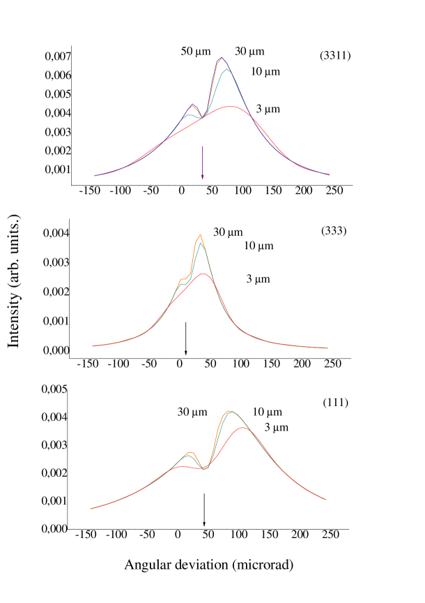
For calculation of the emission angular dependence and energy spectra of rays the codes were made up where the thickness of the crystal was taken into account in accord with the Eqs. (13,14). The next figure shows angular emission function for the crystals of various thicknesses. The low angle reflections (1 1 1), Bragg angle , and (3 3 3), Bragg angle , are compared with the nearly backward reflection (3 3 11), .
III.1 Angular properties, thickness dependence
It is supposed that angular distribution of the incident radiation beam obeys the Gauss law with a characteristic width of 5 rad that is much less than the angular emission range. The crystal is set at different angular positions with respect to the center of distribution of incident beam near the Bragg angles for the reflections (1 1 1), (3 3 3) and (3 3 11) respectively. The curves depicted in Fig. 2 represent the angular variation of the emission intensity over the range of scan.
The temperature of crystal is elevated up to Neél temperature where combined action of the dipole magnetic and the quadrupole electric hyperfine interaction produces pseudo single line Mössbauer diffraction spectrum [Sm2000, ]. Integration over the whole resonance range is fulfilled. The function presenting the emission angular dependence is given by the following expression
| (18) |
where
| (19) |
| (20) |
For definition of and see Eqs. (13) and (14), for definition of and see the text between Eqs. (2) and (3) and immediately after the Eq. (3).
As it was found earlier [Sm2011, ], the multispace quantum interference (involving geometrical energy and spin domains) in the case of combined magnetic dipole-electric quadrupole interaction of nuclear spin with crystalline fields in Iron Borate yields a non-trivial double-hump shape of emission angular curve. However, Fig. 2 shows, that such a shape is formed only in the limit of semi-infinite thickness of the crystal. The path length of radiation in the crystal is determined by expression , where is the crystal thickness and is the angle between the wave vector and inward normal to the crystalline entrance surface. Angle takes the meanings 84.9, 74.5 and 65 degrees for reflections (1 1 1), (3 3 3) and (3 3 11) respectively. So that the limit of semi-infinite crystal should be reached earlier for the reflection (1 1 1). Indeed, already at the thickness of crystal of about 3 m there are signs of the double-hump structure while at 10 m the saturation in thickness is reached for this reflection (see the bottom panel in Fig. 2). In the cases of both (3 3 3) and (3 3 11) reflections the emission angular curve for the thickness of 3 m looks as an asymmetric single line. For these reflections the saturation is reached between 10 and 30 m and at 30 m respectively. The dip positions are given by the expression (see the text after Eq. (3) and before Eq. (16)). These are angular positions of the crystal for Bragg reflections where corrections for the refraction of radiation wave at the entrance to the crystal due to electronic scattering are taken into account. For the reflections (1 1 1), (3 3 3) and (3 3 11) equals 45, 15, 35 rad respectively. The widths of the curves are largest and about the same value for reflections (1 1 1) and (3 3 11) where Lorentz factors are 5.62 and 5.34 respectively, but the reflection strength in the case of reflection (3 3 11) is much higher. We turn to this question in the next paragraph.
III.2 Spectral properties of radiation
On Fig. 3 the spectra of radiation emitted by the crystal are shown for the reflections considered. Integration over angle through the whole angular range of emission is performed (see Fig. 2)
| (21) |
with rad and rad.
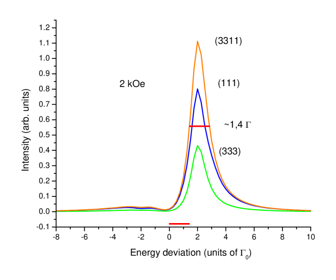
The spectra integrated over the broad angular range have the form of slightly asymmetric single lines with the half widths of about , where is the natural width of nuclear level in the excited state. As seen from the figure, the emission intensity is the highest for (3 3 11) reflection. It exceeds the emission intensity in the (1 1 1) and (3 3 3) reflections by factor of 1.4 and 2.8 respectively. Thus the back reflection turns to be much more powerful than the reflections at low angles. The amplitudes of the coherent scattering for (3 3 11) reflection in Iron Borate are presented in Table 1. One can see that the main contribution to the emission line on the top panel of Fig. 3 is given by 3d and 6th nuclear transitions between ground and the excited states (the most intensive transitions and the relevant matrix elements of nuclear susceptibility are marked in bold).
| Resonance lines | 1 | 2 | 4 | 5 | ||
|---|---|---|---|---|---|---|
| Relative positions of | ||||||
| lines in units of | -2.0843 | -2.0841 | -1.8407 | 1.9445 | ||
| Complex amplitudes | Re Im | Re Im | Re Im | Re Im | Re Im | Re Im |
| -19.91 0.00 | -4.40 0.00 | 0 .00 | -18.54 0.00 | -1.58 0.00 | 0 .00 | |
| 0.00 -0.80 | -0.00 0.00 | 0.00 | 0.00 -0.72 | 0.00 0.00 | 0.00 | |
| 0.00 +0.80 | -0.00 0.00 | 0.00 | 0.00 +0.72 | 0.00 0.00 | 0.00 | |
| -0.03 0.00 | 0.00 0.00 | 0 .00 | -0.03 0.00 | 0.00 0.00 | 0 .00 |
One can easily check that the Kagan-Afanas’ev rule is fulfilled for these nuclear transitions. It is also seen, that the resonant energies for these transitions are nearly coincide, difference between them is only 0.5. Therefore the interference of the considered nuclear transitions provides a single line emission spectrum, find details in Ref. [Sm2011, ]. The same physical reason provides the single line emission spectra in (1 1 1) and (3 3 3) reflections.
In the real conditions the exciting synchrotron radiation is strongly collimated. The divergence of incident beam is usually much less than the angular range of coherent emission, - somewhat about 5-10 rad against 100 rad, when the high resolution monochromator is used. At a fixed angle of incidence of SR the spectrum of the emitted radiation is formed by integration within the narrow angular interval. In Figs. 4 and 5 the emission spectra are displayed where convolution of the angular distribution of the incident radiation with the emission angular distribution is performed for particular settings of the crystal within the emission angular range, as described by the following formulas
| (22) |
| (23) |
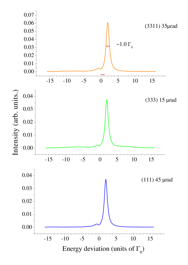
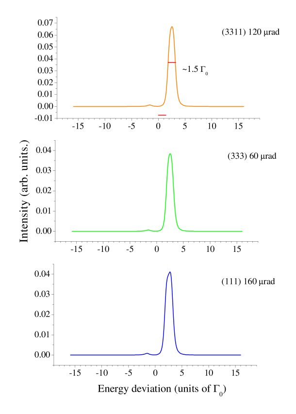
Fig. 4 shows the spectra of the emitted radiation in the positions of the crystal where the dip of the emission angular function is situated, i. e., exactly in the Bragg positions. As it was said above, these positions are 15, 35 and 45 rad for reflections (3 3 3), (3 3 11) and (1 1 1) respectively. For the beam of the exciting radiation strongly limited near these angles there is an advantage to get a sharper the - rays source line. When the crystal is set in the angular position of the dip the half width of the line is only 1. This will allow to reach noticeably higher resolution in investigations of hyperfine structure of Mössbauer spectra. The advantage in the intensity of radiation generated in the case of (3 3 11) reflection evident, the emitted intensity is by about 1.8 times higher the intensity in the cases of (1 1 1) and (3 3 3) reflections. This result is in a good agreement with the theoretically estimated benefit at Bragg angle: , where the Eq. (17) and relevant data for the susceptibilities and the asymmetry factors are used.
If the sharpness of the line source is not that critical another angular setting of the crystall also provides a single line spectrum. This position is located in the middle of the slope on the right-hand side of angular dependence on Fig. 3. The energy distributions corresponding to this angular setting for different reflections are shown in Fig. 5. The nature of the emission line in this angular position is more complicated. A three-dimensional landscape of a Bragg reflection in the vicinity of the nuclear resonance and of the Bragg angle near Neél temperature is presented in Fig. 4c in Ref. [Sm2011, ]. The two main contributions to the interference pattern in the range of positive angular deviations from Bragg angle (corresponding to the right-hand slope in Fig. 2 of the present paper) come from the long lasting wing of the 6th resonance line (provided by the real part of the scattering amplitude) and the line in the center of the resonance range. On the slope of the angular distribution they together form a slightly broadened and asymmetric emission line. The evolution of the emission spectrum with the change of angular position was investigated experimentally in Ref. [Pot2012, ] in the case of (3 3 3) reflection and shown in Fig. 3 overthere. The emission intensity gain in the case of backward geometry is preserved at different settings of the crystal in the emission angular range.
In summary, a possibility of further development of Synchrotron Mössbauer Source (SMS) of 57Fe 14.4 keV radiation was found. The formfactor equal unity in the nuclear resonance scattering for all scattering angles, the possibility to enlarge the asymmetry and the polarization factors as well as the Lorentz factor make the back pure nuclear reflections useful for generation of nuclear resonant radiation by pure nuclear coherent scattering of synchrotron radiation. Particularly, in the case of the nearly back reflection (3 3 11) from FeBO3 crystalline platelet having the planes (1 1 1) parallel to the surface the gain in the intensity of generated Mössbauer radiation can reach factor of two compared to the strong low angle reflection (1 1 1) from the same crystal.
The essential practical advantage is that in backscattering geometry the Mössbauer drive system constructed for the case of low-angle scattering [JSR, ] can be simplified, and namely, be made similar to that used in a regular Mössbauer spectrometer.
The author is deeply grateful to Dr. A. I. Chumakov for friendly motivation and fruitful discussions of this work.
References
- (1) G. V. Smirnov, A. I. Chumakov, V. B. Potapkin, R. Rüffer, and S. L. Popov, Physical Review A 84, 053851 (2011).
- (2) V. Potapkin, A. I. Chumakov, G. V. Smirnov, J-P. Celse, R. Rüffer, C. McCammon and L. Dubrovinsky, J. Synchrotron Rad., v. 19, 559, (2012).
- (3) U. van Bürck, G. V. Smirnov and R. L. Mössbauer , J. Phys. C: Solid State Phys., v. 21, p. 5843 (1988).
- (4) V. Potapkin, A. I. Chumakov, G. V. Smirnov, R. Rüffer, C. McCammon, and L. Dubrovinsky, Physical Review A 86, 053808 (2012).
- (5) G. V. Smirnov, U. van Búrck, A. I. Chumakov, A. Q. R. Baron, and R. Rüffer, Phys. Rev. B 55, 5811 (1997).
- (6) G. V. Smirnov, Hyperfine Interactions 125, 91 (2000).
- (7) T. Mitsui, N. Hirao, Y. Ohishi, R. Masuda, Y. Nakamura, H. Enoki, K. Sakaki, and M. Seto, J. Synchrotron Radiat. 16, 723 (2009).
- (8) Y. Kagan, Hyperfine Interact. 123/124, 83 (1999).
- (9) J. P. Hannon and G. T. Trammell, Hyperfine Interact. 123/124, 127 (1999).
- (10) G. V. Smirnov, V. V. Sklyarevskii, R. A. Voscanian, and A. N. Artem’ev, JETP Lett. 9, 70 (1969).
- (11) G. V. Smirnov, U. van Bürck, R. L. Mössbauer, J. Phys. C: Solid State Phys. v. 21 p. 5835 (1988).
- (12) G. V. Smirnov, V. V. Mostovoi, Yu. V. Shvyd’ko, V. N. Seleznev, and V. V. Rudenko, Sov. Phys. JETP v. 51 p. 603 (1980).