Numerical modeling of ion transport in a ESI-MS system
Abstract
Gas and ion transport in the capillary-skimmer subatmospheric interface of a mass spectrometer, which is typically utilized to separate unevaporated micro-droplets from ions, was studied numerically using a two-step approach spanning multiple gas dynamic regimes. The gas flow in the heated capillary and in the interface was determined by solving numerically the Navier-Stokes equation. The capillary-to-skimmer gas/ion flow was modeled through the solution of the full Boltzmann equation with a force term. The force term, together with calculated aerodynamic drag, determined the ion motion in the gap between the capillary and skimmer. The three-dimensional modeling of the impact of the voltage applied to the Einzel lens on the transmission of doubly-charged peptides ions through the skimmer orifice was compared with experimental data obtained in the companion study. Good agreement between measured and computed signals was observed. The numerical results indicate that as many as 75% ions that exit from the capillary can be lost on the conical surface of the skimmer or capillary outer surface due to the electrostatic force and plume divergence.
I Introduction
The development of electrospray ionization (ESI) mass spectrometry (MS) 25 years ago has opened an opportunity to characterize substances of broad natureSmith ; Kebarle ; Fenn , most notably proteins. A major deficiency of operation of mass analyzers utilizing atmospheric ion sources is that only a small fraction of molecular ions generated from charged microdroplets reaches the ion detector. A significant loss of analytes takes place during transport of the ions through the MS inlet systemLin , which is often a long heated capillary with a 400-600 m i.d. followed by a subatmospheric chamber with a skimmer; the latter separates the low vacuum from the high vacuum sections of the MS system. A two-fold increase in the ion transmission from a nano-ESI source to the mass analyzer was demonstrated on a flared inlet capillary Wu . More substantial increase in the ion transmission from an ESI source to the mass analyzer was achieved using ion funnels Kelly . In general, more efficient operation of ESI sources coupled with a heated inlet capillary and subamospheric/low vacuum ion transport system downstream of the inlet has a tremendous impact on the field of biological mass spectrometry. Such an operation may be achieved by reducing the unspecific chemical noise, the loss of analyte ions on capillary walls or orifices providing differential pumping, and the in-source fragmentation of fragile ions, which determines the detection limit in a particular mass analyzer and the time needed for individual MS and MS/MS analyses.
Considerable progress in reducing ion loss in atmospheric interfaces is visibly hampered by a lack of comprehensive and accurate system modeling, both at the microscopic physical and fluid dynamic levels. Ideally, this comprehensive modeling would comprise the accurate simulation of droplet evolution (fission and evaporation), production of ions from droplets, and ion loss inside the heated capillary and on the MS inlet elements downstream. At present, there is no self-consistent and complete model capable of numerical simulation of such an evolution. Instead, researchers study and analyze different aspects of that evolution, separated in physical and spatial terms. For example, droplet evaporation and fission is usually separated from gas/ion transport, and gas flow in the inlet capillary is separated from the flow in the subatmospheric sections. There are several reasons for such simplifications. The most important is the change in flow regimes from viscous to molecular over a short spatial scale, associated with the change in gas density from atmospheric levels at the inlet to microTorr levels in the high vacuum section of the MS. There is also a dramatic change in time scale - from slowly changing flow in the long inlet capillary to rapidly propagating supersonic expansion flow downstream of the capillary.
Yet another complexity for comprehensive modeling of ESI-MS droplet/ion evolution is related to droplet-to-ion transformation. The transport of micron size droplets of solvent and ions in carrier gas flow is governed primarily by drag force from the carrier gas and, in addition, by electrostatic force from applied fields and space charge. While the droplet transport often may be uncoupled from gas transport, the difficulty of modeling the evolution of micro- and nanodroplets stems from the lack of detailed microscopic information (mostly due to experimental challenges) on droplet evaporation and fissionHogan . Lagrangian particle tracking may be used for modeling droplet evolution Longest2004 , and a CFD solver based on the solution of Navier-Stokes equations for droplet transportLongest2007 ; wup . Depending on the selected capillary temperature and, importantly, the temperature gradientEugene , the formation of analyte ions from nanodroplets usually occurs not in the capillary head but inside a longer section of the capillary, so the transport of these ions through the capillary should take into consideration gas densities that can be significantly lower than atmospheric. Knudsen numbers calculated from the characteristic flow dimensions, such as capillary i.d. or skimmer diameter, typically are on the order 0.01 to 0.1 for flows expanding through the capillary, and 0.1 to 10 in the ion transport systems kept at typical pressures of 1 Torr (ion funnels) or 0.01 Torr (RF multipoles). The flows at such Knudsen numbers are in a regime transitional from continuum to free molecular. Neither continuum formulation, such as that based on the Navier-Stokes equations, or free molecular, such as test particle methods, are applicable to compute gas flows at such conditions. Numerical analysis of such flows requires a kinetic approach to be used and thus the consideration of the Boltzmann equation, the fundamental equation of the kinetic theory, that properly accounts for flow non-equilibrium.
The numerical complexity and high computational cost of a three-dimensional solution of the Boltzmann equation that inherently involves development and application of highly scalable parallel algorithms are the obvious reasons for its very rare application to ESI-MS ion transportation problems. Since deterministic approaches to the solution of the Boltzmann equation, such as its numerical integration, are prohibitively expensive from the computer time stand point, the only feasible way to solve it is statistical, based on the direct simulation Monte Carlo (DSMC) method DSMC . The known applications of the DSMC method for gas/droplet/ion transport in ICP-MS are Ref. [(13)] where evaporation and coalescence affected droplet evolution was studied, Ref. [(14)] where the carrier gas flow inside an ion funnel was examined, and Ref. [(15)] where carrier gas flow from a capillary into a skimmer was modeled. Note that Ref. [(14)] represented, in fact, a three-step approach where the DSMC inflow boundary conditions at the inlet capillary exit were uniform values approximated from Navier-Stokes simulations and the DSMC fields were in turn used for successive particle tracking with a SIMION package. In Ref. [(15)], a two-dimensional setup was used with a uniform capillary exit approximation; the calculations of ion trajectories were not presented.
This work is the first step toward a comprehensive model of ion transport in ESI-MS systems, which includes droplet evaporation, fission, and transport, along with the formation, transport, and loss of ionized analytes and solvent clusters (residual nanodroplets) in a wide range of . A pragmatic approach to satisfying this goal is to first simulate the backbone of the process, the multi-regime gas dynamic transfer from atmosphere to high vacuum. Once established, a robust capability for modeling gas dynamics in the system will act as the foundation on which to add each of the additional pieces to the comprehensive model. For instance, accurate thermal and pressure data is required as inputs to droplet evaporation. Local gas flow velocity, density, and temperature, as well as collisional cross sections, are required for compute ion transport in subatmospheric and low-vacuum sections of mass spectrometers. Thus, this work focuses on establishing an accurate gas dynamic backbone as the first step to a comprehensive ESI-MS numerical model. Consequently in this work, ions are not considered until the DSMC portion of the simulation and then introduced near the capillary exit with properties corresponding to the local carrier gas macroparameters. This assumption will be addressed later. While predominately gas dynamic, this limited inclusion of ions allows the simulation to be compared directly with experiment while changing only one key parameter - Einzel lens potential. This will be used as the characteristic of interest in assessing the accuracy of the gas dynamics simulations in subatmospheric interfaces and the validity of this model as the foundation for future additions and refinements.
The DSMC method is used in this work to model the ion transport in a carrier gas flow expanding through a long capillary into a low-pressure background gas before passing through a skimmer into the hexapole chamber. The main objective of the work is to analyze the efficiency of the traditional capillary/Einzel lens/off-center skimmer approach, currently used in portable mass spectrometersMisharin , and study the effect of changing voltage at the Einzel (tube) lens. The companion experimental study provides not only the actual geometric and flow properties of interest, but also solid ground for model validation. The off-center location of the skimmer does not allow one to use the simplifying assumption of an axially symmetric flow utilized in previous studiesdebbie ; greek . Thus, full three-dimensional modeling of the ion-gas mixture is performed here. A CFD software package, CFD++, was utilized for modeling the capillary flow that provided the hand-off starting surface for the DSMC simulations, while a multi-physics solver COMSOL was used to calculate the electric field and related force term in the Boltzmann equation.
There are several issues considered in this work that were omitted in previous research. First, and most notably, this is the first truly three-dimensional simulation that uses a kinetic approach to model the subatmospheric and low vacuum sections of the MS system. The application of a kinetic approach based on the solution of the Boltzmann equation provides accurate description of the flow as it takes into account its microscopic nature at the level of the velocity distribution functions, thus resolving flow non-equilibrium. Flow three-dimensionality is critical as it allows one to consider the widely used off-axis setup that greatly reduces the contamination of the MS system downstream with residual droplets. Second, the simulation includes fully coupled ion-carrier gas flow in the low vacuum section. Third, the numerical modeling presented in this work takes into consideration the flow inside a capillary as a precursor to the flow in the low vacuum section, thus avoiding a uniform inflow approximation that may result in significant accuracy losssidejet .
II Numerical Approach and Flow Conditions
In the physical system, micron-size solvent droplets are formed at the tip of a Taylor cone formed in the ESI source, and move through atmosphere into the inlet capillary. The capillary has an inner diameter of 0.5 mm and a total length of 100 mm. In order to provide high-temperature environment needed for droplet evaporation and subsequent ion formation, the capillary is heated to 227 C (500 K). The droplet fission and evaporation in the capillary produces ions mostly by charge residueDole , but also by ion evaporationIribarne mechanisms. Then, the mixture of ions and carrier gas molecules expands out of the inlet capillary into a chamber where gas pressure is kept at 1 Torr. As the ions travel in the plume, they are focused by the electrostatic force produced by the potential difference between the Einzel lens, capillary, and skimmer. Some of them then move through the 0.6 mm diameter skimmer into the hexapole chamber kept at 0.01 Torr.
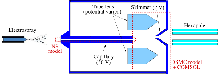
A partially simplified geometry of the skimmer in the first subatmospheric chamber and the Einzel lens in the inlet of the mass spectrometer was used in computations. The schematics of the considered setup is plotted in Fig. 1(a) in a plane aligned with the inlet capillary axis and the skimmer axis. This geometry has been utilized in earlier models of quadrupole ion traps (Finnigan LCQ, ThermoFisher, San Jose) and in several mass spectrometers equipped with atmospheric interfaces built by MassTech Inc. Note that the center of the skimmer is shifted off the capillary axis to avoid contamination of downstream chambers by droplets not fully evaporated in the heated inlet capillary.
Due to the five order of magnitude pressure drop from the ESI source to the hexapole chamber, subsonic flow in the inlet capillary that requires long time to reach steady state, and three-dimensionality of the skimmer chamber setup, it is practical to separate the problem into two steps. The first step considers the flow inside the capillary; it starts in the ESI chamber and ends in the first subatmospheric chamber of the MS. The gas flow regime is continuum at the capillary entrance and near-continuum at its exit. Thus, the Navier-Stokes equations may be used to calculate that flow. Additionally, the flow is axially symmetric. The computational domain used for the first step is schematically shown in Fig. 1(a), denoted as “NS model”. The second step includes the flow from the capillary to the skimmer. The flow regime is transitional, and the DSMC method is therefore used (denoted “DSMC model” in Fig. 1(a)). It is important to mention that an accurate splitting of the flow into an internal and external parts requires the hand-off surface to be located in the supersonic region. The hand-off surface serves as the inflow boundary condition for second step, with flow properties obtained in the first step. The supersonic velocity at that surface guarantees that gas molecules and ions from the downstream portion of the plume do not travel upstream. It is usually sufficientss to set the hand-off surface at a Mach number isosurface.
Modeling of the first step was performed with a computational tool CFD++ CFD++ . CFD++ is a flexible computational fluid dynamics software suite developed by Metacomp Technologies for the solution of steady and unsteady, compressible and incompressible Navier-Stokes equations, including multi-species capability for perfect and reacting gases. CFD++ was proven to be a robust tool for complex gas dynamic flows, both external and internalcfd1 ; cfd2 . In this work, a turbulent Reynolds Averaged Navier-Stokes capability of CFD++ is applied. The simulations were conducted with a 2nd order in space, Harten, Lax, van Leer, contact discontinuity Riemann approximation algorithm. The computations use a three-equation turbulence model turb . Implicit time integration was used. A perfect gas model of air was used in this work as the impact of real gas effects for the temperatures under consideration is negligible . The capillary surface was assumed isothermal with a constant temperature of 500 K. Second order slip boundary conditions were applied at the wall. A symmetry condition is used at the capillary axis. A stagnation pressure-temperature boundary condition was set at the inflow boundary and a backpressure imposition was applied at the outflow. Note that the inflow and outflow boundaries were set sufficiently far from the capillary walls so that the Mach number at the former and at the latter. A multi-block computational grid was used with the total number of cells over 200,000. Note that solution convergence was verified for several grids to obtain grid independent results.
Modeling of the second step was conducted with a DSMC solver SMILE SMILE . The three-dimensional parallel capability of SMILE was used here. In the past, SMILE has been extensively used to solve the Boltzmann equation without and with the force term, and validated in a number of multi-dimensional problems smile1 ; smile2 ; smile3 . The majorant frequency schemeMFS was used to calculate intermolecular interactions. A three-species mixture was considered, with the standard atmospheric composition of molecular nitrogen and oxygen, and a trace species of ion with the initial mole fraction of 10-5 (small enough not to impact the gas flow). A species weighting scheme was applied in gas-ion collisions. Ion atomic mass was 1348 Da (doubly charged peptide ions with ). The intermolecular potential was assumed to be a variable hard sphere for air species and hard sphere for air-ion collisions. The reference diameter and temperature exponent were chosen from Ref. [(12)] for air. Ions had a diameter of 16.82 ÅTao . Energy redistribution in molecular collisions between the internal and translational modes was performed in accordance with the Larsen-Borgnakke modelLB . Temperature-dependent relaxation numbers were used. The reflection of air molecules on the surface was assumed to be diffuse with complete energy and momentum accommodation. A surface temperatures of 300 K was set at the outer capillary surface, the Einzel lens, and the skimmer. The surface was assumed fully adsorptive for ions. The total number of simulated particles was approximately 50 million with 3 million collision cells. The collision grid was automatically adapted based on the local density. The inflow boundary condition was extracted from the Navier-Stokes field obtained at the first step, along the isoline. The outflow was a uniform field with a gas pressure and temperature of 1 Torr and 300 K, respectively, in the plume expansion chamber, and 0.01 Torr and 300 K, in the hexapole chamber.
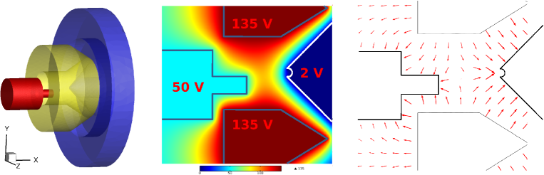
The impact of the electrostatic force on ion motion was taken into account in the DSMC simulations. The force values were pre-calculated with the COMSOL software. The three dimensional geometry used in the DSMC calculations was imported into COMSOL Multiphysics®, in which the Electrostatics package was used to set potentials on the appropriate surfaces. Once set, a three dimensional lookup table was generated which gave the electric field vectors throughout the DSMC domain. That lookup table was exported and subsequently used in the DSMC process to apply spatially appropriate forces on the molecules through the first order linear interpolation. Figure 1(b) shows the individual surfaces used within the COMSOL model and two dimensional slices of the electric potential and field vectors, respectively, for a lens potential V.
III Experimental Setup
The electrospray source was comprised of a syringe pump and microfluidic union (IDEX, Oak Harbor, WA) connecting the syringe needle with a short piece of fused silica capillary terminated with the ESI tip (New Objective, Woburn MA). The sprayed acedified (1% formic acid) water/acetonitrile solution (70/30%, v/v) contained M of peptide substance ( Da). All solutions and peptide were purchased from Sigma (Sigma-Aldrich, St. Louis, MO, USA). The ion current measurements were performed using a prototype unit similar to the one used in a portable mass spectrometerMisharin . The MS inlet was a glass-lined stainless steel capillary (0.5 mm i.d, 1.6 mm o.d., 10 cm long) from SIS (Ringoes, NJ) with its head (2 cm long) embedded in a massive copper block. The temperature control system maintained a constant temperature of 120-220\celsius for the capillary in the subatmospheric chamber kept at approximately 1 Torr gas pressure. A conical skimmer separated the low-vacuum section (1 Torr) of the interface containing a tube lens and medium-vacuum (0.01 Torr) section with the hexapole ion guide. Ion current measurements for selected analyte ions were performed using a quadrupole ion trap.
IV Gas Flow Through Capillary
As discussed above, the two-step modeling of ion transport into the hexapole chamber starts with the Navier-Stokes solution of the capillary flow. The flow velocity in the axial direction for the Navier-Stokes computations is shown in Fig. 2(a). The Reynolds number in the capillary exceeds 3,000 and thus one can expect noticeable turbulence effects. To illustrate, results are shown for the turbulent and laminar models (the simulation setup is identical in these computations except for the turbulence terms being turned on and off). The result is stretched in Y direction in order to provide better detail. Most of the ESI and subatmospheric chambers is not shown. In both cases, the flow velocity quickly increases downstream of the capillary entrance. The velocity increase is mostly in the core flow, as the velocity near the wall does not exceed 10 m/s due to relatively high gas density and therefore thin boundary layer. As expected, the turbulent flow is generally characterized by lower velocities, with the difference between the turbulent and laminar solutions equals to 10% in most of the capillary. This difference decreases at the capillary exit, where the maximum flow velocity is about 555 m/s for the laminar case and 530 m/s for the turbulent case.
The gas temperature for these two cases is shown in Fig. 2(b). Note that although the hot wall and gas convection result in a significant increase in gas temperature in the core flow, it always stays noticeably lower than the wall temperature. The maximum temperature at the capillary axis is observed at approximately 80% capillary length. Further downstream, flow acceleration due to the proximity of the exit results in a temperature drop. There is a visible difference between the turbulent and laminar result, although most of the difference is observed at the axis, near the maximum temperature region. The maximum temperature at the axis is 468 K for the turbulent case and 442 K for the laminar case. This comparison indicates that turbulent mixing, which results in lower flow velocity (and thus longer residence time) and higher gas temperature, may be expected to significantly impact the droplet evaporation and fission process in the downstream half of the capillary.
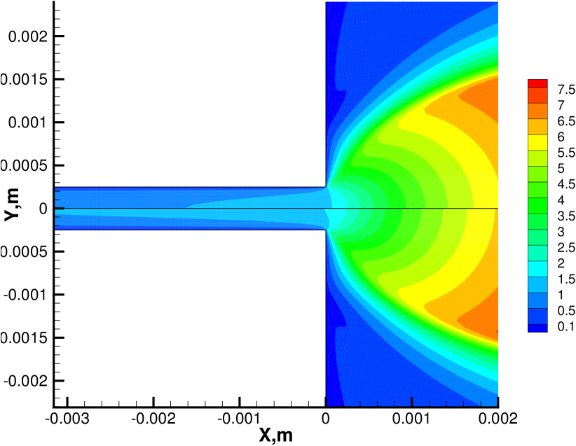
Let us now consider the details of the flow in the vicinity of the capillary exit, as this is where the Navier-Stokes to DSMC hand-off surface is located. The Mach field is presented in Fig. 2(c). Typical for flows in capillaries that connect high and low pressure chambers, the supersonic flow is observed noticeably upstream of the capillary exit (which illustrates the limitations of approximations used in Refs. [(14; 15)]). The location of the M=1 isoline visibly changes when turbulence is accounted for, as it crosses the flow axis at 4 mm upstream of the exit in the laminar case and at 1.5 mm in the turbulent case. Nevertheless, the difference between the two cases in the expanding plume is much smaller. In the plume, the turbulent-vs-laminar difference is only on the order of 3%, which is very similar to the 3% mass flow rates for these cases, 1.25 kg/s for turbulent and 1.28 kg/s for laminar flow. Generally, these calculations show that while there is a visible impact of flow turbulence on gas properties inside the capillary, its impact on the plume, and thus gas properties at the starting surface located along the M=3 isoline, is minor.
This is further illustrated in Fig. 2(d) where the gas pressure field is presented. For both cases, pressure gradients inside the capillary are negligible in the radial direction, except in the immediate vicinity of the exit. In the plume, the difference between the turbulent and laminar cases is also negligible. Still, in all results shown in the following sections, the hand-off surface extracted from the turbulent flow solution was used. Note that the pressure at the exit is about 16 kPa, over ten times higher than the background pressure. The gas mean free path at the exit is about 0.5 m, so that the capillary diameter based Knudsen number is about 0.001, and thus well within the applicability of the continuum approach (Navier-Stokes). At (location of the hand-off surface), the mean free path increases only an order of magnitude, so that the continuum approach may still be used.
V Expanding Flow Modeling
The information on gas macroparameters in the plume nearfield, obtained as the result of the capillary flow modeling discussed in the previous section, allows one to use these macroparameters as the inflow boundary condition (hand-off surface) in the subsequent DSMC modeling. The Maxwellian distribution function was assumed for gas molecules and ions originating at the inflow boundaries. A constant value of the ion mole fraction of 10-5 was used, small enough to avoid impact on the carrier gas flow. The ion properties therefore were assumed to be equal to those of the gas. Note that the gas density in that region is still too high for noticeable ion-gas separation, confirmed by comparison of the obtained results with those for the handoff-surface located at (not shown here).
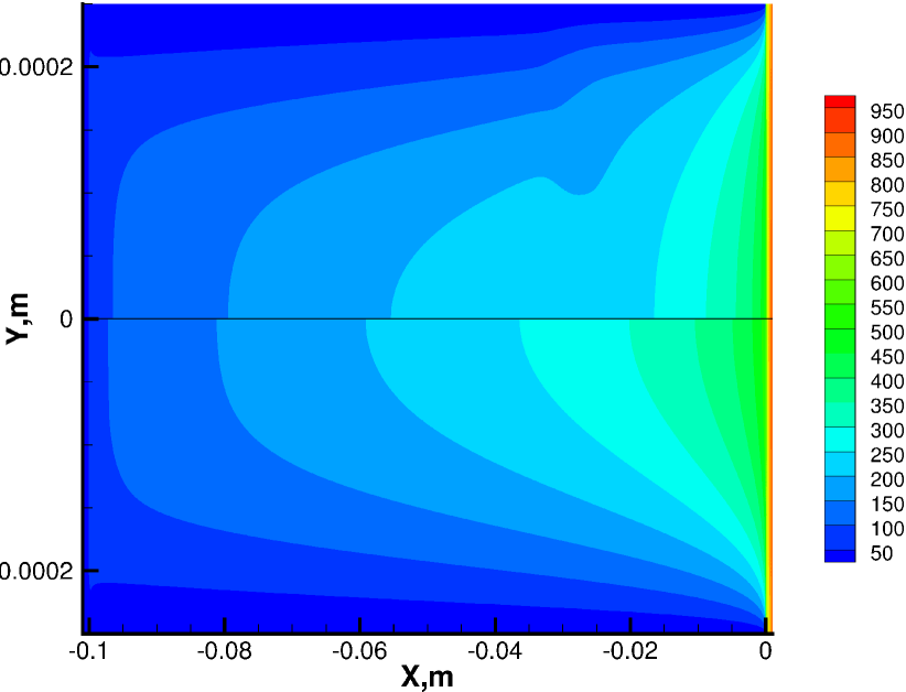
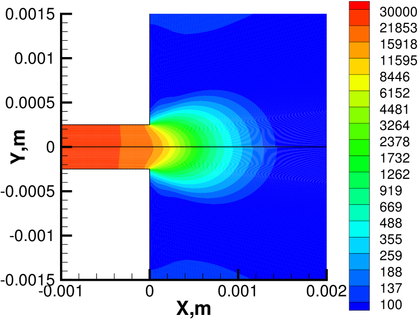
The carrier gas number density in the subatmospheric chamber is given in Fig. 3(a) for an Einzel lens potential V. Hereafter, a two-dimensional slice of the three-dimensional flowfield is taken at . The capillary axis is and its exit plane is at . The dark region near the origin of the coordinate system indicates the location of the hand-off surface. The upper and lower pentagons show the position of the Einzel lens (shifted 1 mm upward in the plane), and the remaining surface indicates the location of the skimmer (centered at mm). Although the case of zero Einzel lens potential is shown here, varying Einzel lens potential does not impact the carrier gas properties due to the low concentration of ions. The presented field shows that the plume density reaches the background gas level after the first two capillary diameters. Further expansion decreases density down to about 0.5 of that of the background. Elevated density near the entrance of the skimmer shows some moderate impact of the plume in that region. Note also that plume formation inside the skimmer clearly points upward, which is also due to the presence of the capillary expansion. It is important to note that although the low gas density behind the skimmer results in some plume molecules (and thus ions) being transported through the skimmer, the vast majority of plume molecules (over 98%) miss it. Since the path of ion expansion is not expected to differ strongly from that of air, such a low transmission provides a clear indication of the importance of the Einzel lens in the considered setup.
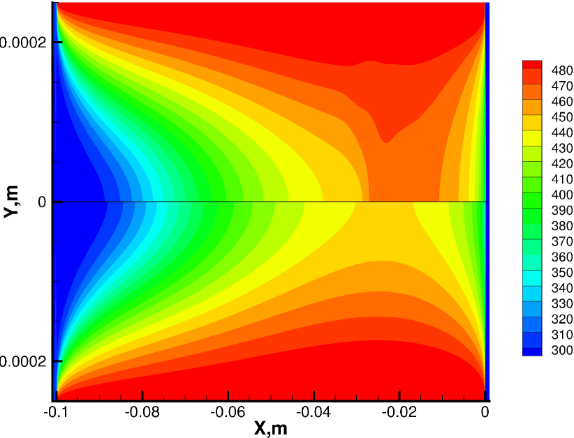
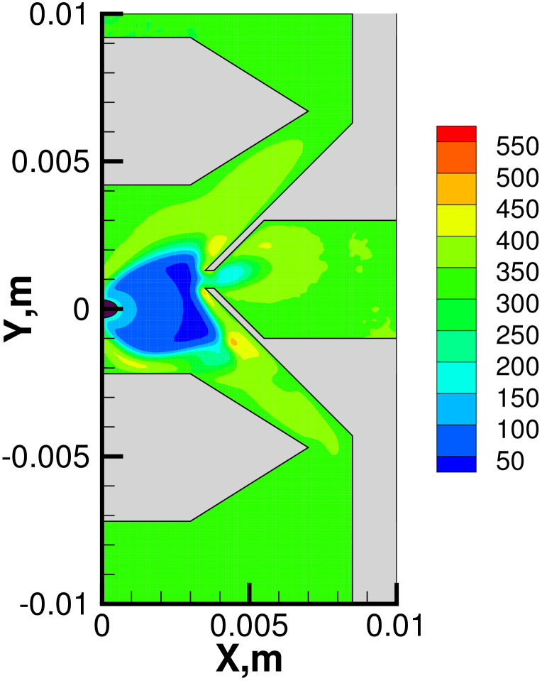
The gas temperature field for V is presented in Fig. 3(b). In the plume expansion, the gas cools down and the temperature drops below 50 K (the lowest observed value is 43 K). The cold region propagates down to the skimmer, almost reaching its surface. The elevated temperatures near the skimmer (in excess of 400 K) provide some insight into flow non-equilibrium. The reason for the temperature to be higher than the skimmer surface temperature of 300 K is that gas rarefaction results in a non-Maxwellian, bimodal, velocity distribution function, which distorts the traditional and calculated idea of temperature. The bimodality is due to nearly counter-propagating plume molecules and molecules reflected on the skimmer surface. At the entrance of the skimmer, the temperature reaches about 300 K and then falls again due to gas expansion. The results show that due to the combination of low temperatures between the capillary exit and the skimmer, and relatively low densities in that region, no noticeable change in droplet evaporation due to the carrier gas will occur downstream of the capillary exit. The conclusion should still be valid even if the skimmer is heated.
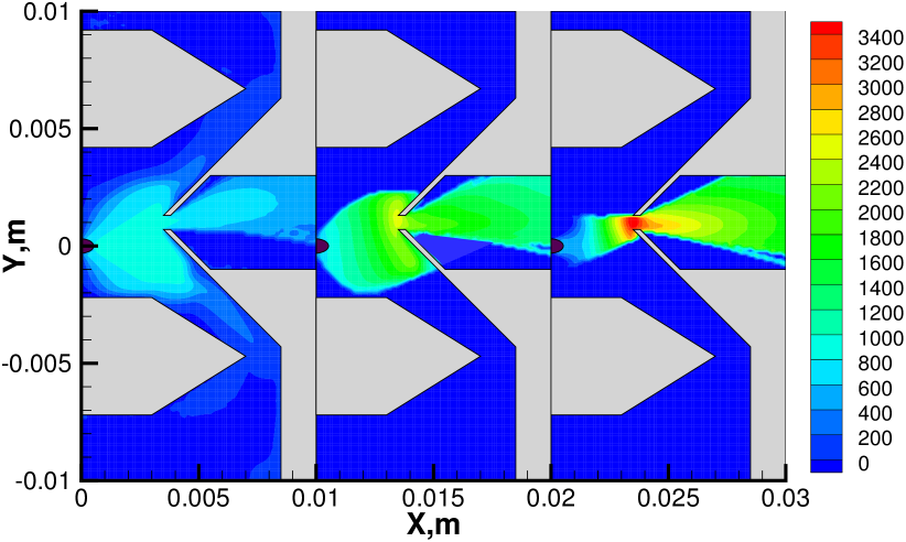
Consider now the properties of ions as they are impacted by the Einzel lens potential. The ion velocity is shown in Fig. 4(a) for the three values of the Einzel lens potential . In the absence of an applied potential, , the ion velocities and trajectories largely follow those of the carrier gas. The maximum flow velocity of ions, about 930 m/s, is close to that of gas, 960 m/s, which corresponds to the conventional gas expansion at a stagnation temperature of 300 K. The maximum velocity is observed at the capillary axis. Some decrease in ion velocity near the skimmer walls is related to collisions with gas molecules reflected on the walls. A higher rate of velocity decrease corresponds to higher gas density near the wall (see Fig. 3). Collisions with gas molecules also cause some decrease in ion velocity downstream of the skimmer entrance. The ion flow velocity field drastically changes when a 45 V potential is applied to the Einzel lens. Most importantly, the electrostatic field created by the capillary-lens-skimmer potential difference starts to focus the ions to the skimmer. The electrostatic force, on average, reduces the radial velocity component of ions, which in turn deflects their trajectories toward the lens axis. In addition, the axial velocity component noticeably increases as ions travel from the capillary to the skimmer, reaching about 2,400 m/s near the skimmer entrance. Collisions with air molecules decrease that velocity to less than 1,400 m/s a few millimeters downstream of the entrance. For a 135 V potential, the focusing effect is even more substantial. However, in the first two millimeters of the capillary exit, the average ion velocity is smaller than that for V and even case. The reason for this is that the high voltage at the lens creates an electrostatic field that decreases ion velocity in that region and pushes some ions back towards the capillary. As the ions travel toward the skimmer, they are rapidly accelerated to average velocities of about 3,500 m/s. Then, they are decelerated inside the skimmer, where the effect of the electrostatic field is smaller than that of the gas-ion drag. It may be expected that, similar to ion deceleration, small droplets would also be decelerated, thus significantly increasing their internal temperatures and evaporation rates.
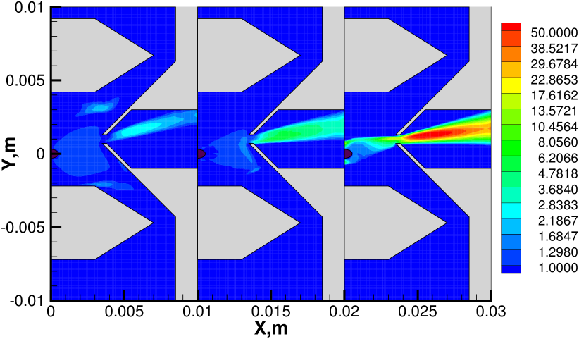
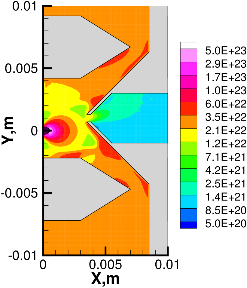
When the background pressure in all subatmospheric sections is fixed, the efficiency of the lens-skimmer setup directly depends on the amount of ions that come through the skimmer, as well as the amount of air molecules from the plume that the skimmer prevents from entering into the hexapole chamber. A good indicator of the setup efficiency is therefore the ion mole fraction, with higher mole fractions behind the skimmer being desirable. The ion mole fraction fields for three different lens voltage are given in Fig. 4(b). All mole fractions were normalized by the value set at the inflow boundary to provide a more informative comparison. For the V, as can be expected for a heavy-light gas mixture expansion, the ions are concentrated near the capillary axis, although their normalized mole fraction does not exceed 1.1. The ion concentration decreases for large angles from axis, approaching 0 for 90∘. The largest ion mole fraction is observed inside the skimmer, where it reaches 2.8 due to smaller deflection of ions from their original plume trajectories, as compared to air molecules. This trend continues for V, although in the latter case the impact of the electrostatic force from the Einzel lens results in maximum ion mole fraction of more than 5 that of the inlet. Moreover, the lens influences the average angle of the ions that come through the skimmer, turning the ions toward the skimmer axis. Note that both for and V, the mole fraction of ions drops near the skimmer walls. This is due to the fully adsorptive wall condition assumed for ions in this work. Note that an incomplete adsorption is not expected to change the flow inside the skimmer, as the vast majority of reflected ions would be pumped out of the chamber. For the 135 V, case, one can clearly see the backflow of ions near the starting surface that are diverted by the field toward the capillary surface. Of the ions that are not diverted, most travel through the skimmer entrance, where the resultant normalized ion mole fraction reaches 70, or 25 times that for V. Some decrease of the mole fraction further downstream is due to accumulation of air molecules reflected on the horizontal skimmer walls.
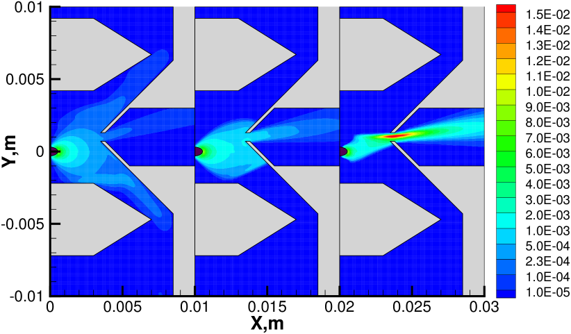
The most important flow property, from the standpoint of system efficiency is the ion mass flux, which linearly impacts the MS reading. The impact of the lens potential on the ion mass flux is presented in Fig. 4(c). In the absence of the lens potential the ion mass flux is maximum at the capillary axis and decreases in radial direction nearly following the cosine law. Some deviation from the cosine law at larger distances from the axis is related to the gas density variation in those regions. For the V case, ion focusing by the lens is obvious and the result is a factor of five increase in the ion mass flux at the skimmer entrance as compared to . Also, although none of the ions are diverted by the lens back to the capillary wall, a large amount of ions end up on the skimmer walls. For both 0 and 45 V, the variation of the ion mass flux across the skimmer entrance is small. For the 135 V potential, that variation is over three times and the maximum value is over 15 times larger than that for 45 V (it is in fact even larger than that inside the capillary). Note that most of the ions that approach the skimmer come through its entrance and only few stick to the wall (all of them in the lower half of the skimmer). This may be a clear indication that for a given geometrical setup (skimmer and Einzel lens size and location), further increase in lens voltage may not increase the ion mass flow through the capillary. This is because the ion back flow will further increase with the voltage, while there is a limited amount of ions that can be better focused into the skimmer.
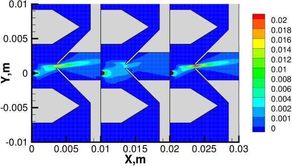
Prior to comparing the numerical results to the experiment, it is reasonable to study the sensitivity of such a comparison to some numerical and experimental uncertainties. The carrier gas related uncertainty is considered relatively minor. The focus below is on ion related changes. The two points examined here are the impact of the uncertainty in the ion diameter, which directly influences the ion-gas interaction, and possible MS signal contamination by water droplets. Figure 5 compares the ion mass fluxes, normalized by the inflow values, obtained for the following computations, all conducted at V: (i) the model ions used above (i.e., peptide ions with , doubly charged, with the ion/gas collision diameter of 16.82 Å), (ii) water clusters (100-mers) carrying a single charge, and (iii) peptide ions with , doubly charged, but with a diameter reduced to 14 Å. The results show that for the same concentration of charged water clusters, their mass flux is noticeably different. The lower charge-to-mass ratio results in poor focusing by the lens, and many droplets will collide with the skimmer surface, thus reducing contamination. The mass flux at the skimmer entrance is on average approximately a factor of 3.5 smaller than for the baseline model. Note that the mass flux at the entrance should decrease with the increase of the droplet mass. Direct analysis of contamination of the signal with charged water clusters is complicated by possible droplet heating and evaporation downstream of the skimmer entrance due to droplet deceleration by the air flow, but it is believed that such contamination does not have determining effect on the signal. Although the ion diameter used above is believed to be accurate within a few percent, a 20% smaller diameter is used in order to estimate its possible impact, even though such a value is extremely unlikely. The decrease of the effective peptide ion/gas collision diameter results in somewhat better focusing into the skimmer entrance, as the maximum value of the mass flux is over 40% larger than that for the same ion but with ion/gas collision diameter of 16.7Å. On the other hand, smaller drag results in more ions being pushed back to the capillary by the electric field, so that the total mass flow through the skimmer is in fact 10% smaller than that for the ions with larger collision diameter ions. Generally, the impact of the ion diameter and ion-air collision uncertainty is believed to be small.
VI Comparison with Experimental Data
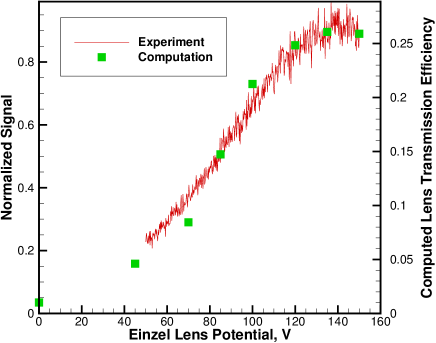
The Einzel lens voltage was varied, both numerically and experimentally, and the output ion signal recorded. While the experimentally measured signal directly reflects the number of doubly charged peptide ions trapped into the MS, the numerical signal is based on the number flux of ions that reached the internal part of the skimmer. The possible ion loss further downstream is not taken into consideration. Although the impact of such an approximation is small, it may still somewhat reduce the high-to-low voltage signal ratio, as the ion flow passing through the skimmer entrance is more divergent for lower (see Fig. 4(a)). Another numerical uncertainty is related to the use of a two-step approach, which is also expected to skew the signal ratio toward the lower voltage as compared to a hypothetical approach that would compute all droplet/ion evolution in one step. This is because the two-step approach does not track ion trajectories before they reach isoline, assuming that they travel with the flow and neglecting the electrostatic field effect. The numerical uncertainties related to other factors, both physical (viscosity, heat conductivity, etc.) and numerical (numbers of cells, simulated particles, timestep, etc.), as well as the statistical error, are believed to be small (less than 3 percent combined).
The comparison of measured and computed ion signal is shown in Fig. 6, where the experimental data is normalized by the maximum signal, and the numerical points are normalized to provide the best fit with the data. Numerical modeling captures the signal increase with voltage quite reasonably. Both computation and experiment show the maximum signal at about 135 V, after which the signal starts to drop due to ion diversion back to the capillary surface. The underprediction of ion signal in the computations for smaller voltages (less than 100 V) is attributed primarily to the effects of the signal calculation and two-step approach, discussed earlier in this sections. Figure 6 also presents the Einzel length efficiency (the right axis), calculated numerically as the ratio of ions passed through the skimmer to the number of ions that left the capillary. It is seen that although the lens allows for great increase in transmission, from less than 2% for to over 25% for V, this experimental configuration still shows large room for improvement. Even for V, almost 75% of ions are lost at the skimmer and external capillary walls.
VII Conclusions
A two-step numerical approach for ion transport from a capillary to a skimmer in a conventional ESI-MS setup is presented. The approach is based on the solution of the Navier-Stokes equations in the capillary and the solution of the Boltzmann equation for the gas/ion transport from the capillary to the skimmer. The direct simulation Monte Carlo method is used to solve the Boltzmann equation, with a pre-calculated electrostatic field force term defined by the potential difference between the capillary and the skimmer. The solvers used in this work are CFD++ for the Navier-Stokes equations, SMILE for the Boltzmann equation, and COMSOL for the electric field. The two-step approach is applied to predict the change in the peptide ion signal as a function of the Einzel lens voltage. A companion experimental study was also performed. Good agreement between the measured and the computed ion signals was observed. An optimization of the potential applied to the lens resulted in approximately 10-fold increase of ion transmission as compared to the case where no focusing field was present. The increase is attributed to efficient focusing of ions accelerated to the skimmer entrance. Still, even for the optimum voltage, maximum capillary-to-skimmer ion transmission was found to be only around 25%, with the remaining 75% of ions being lost on the external capillary surface and, to a lesser degree, on the skimmer surface. Ion loss near the skimmer due to peptide ion overheating and following fragmentation was not considered in this model, yet, no in-source fragmentation was observed in the companion experiment. Obviously, the overheating may be an issue for more fragile ions.
Gas flow inside the considered 100 mm long, 0.5 mm diameter, capillary is turbulent (), and the analysis of the turbulence effect has been conducted. It was found that flow turbulence noticeably decreases the flow velocity and increases the maximum temperature in the core flow and thus will affect the droplet evaporation process. The presence of turbulence has only small effect on the gas flow properties downstream of the the exit of the heated capillary. The temperature in the expanding plume stays below 100 K almost to the surface of the skimmer. Nanodroplets and water clusters which can reach that region are not expected to evaporate in collisions with residual gas, even if one uses elevated temperatures for the inlet capillary and skimmer. In the presence of significant potential at the Einzel lens, the ions were found to accelerate to over 3,000 m/s upstream of the skimmer orifice, and then slowly decelerate through ion-air collisions downstream of the skimmer orifice. Such a deceleration leads to heating and evaporating of small droplets or clusters traveling through the skimmer and to collisional activation of ion vibrational modes (skimmer-induced fragmentation).
VIII Acknowledgments
The authors wish to thank Prof. Rebecca Webb and her students for their helpful discussion regarding COMSOL. The work was supported in part by the Air Force Office of Scientific Research (Dr. Mitat Birkan). The modeling effort used, in part, the Extreme Science and Engineering Discovery Environment (XSEDE), which is supported by National Science Foundation grant number OCI-1053575. This work was also supported, in part, by a grant of computer time from the DoD HPC Modernization Program (HPCMP) at the ERDC DoD Supercomputing Resource Center (DSRC). The experimental efforts have been supported in part by NIH Grant 1R43GM103358.
References
- (1) Smith, J.N., Flagan, R.C., Beauchamp, J.L.: Droplet Evaporation and Discharge Dynamics in Electrospray Ionization. The Journal of Physical Chemistry A 106(42), 9957-9967 (2002)
- (2) Kebarle, P. Verkerk, U.H.: Electrospray: From ions in solution to ions in the gas phase, what we know now. Mass Spectrometry Reviews, 28(6), 898-917 (2009)
- (3) Fenn, J.B.: Electrospray Wings for Molecular Elephants (Nobel Lecture). Angewandte Chemie International Edition. 42(33), 3871-3894 (2003)
- (4) Lin, B., Sunner, J.: Ion transport by viscous gas flow through capillaries. J. Am. Soc. Mass Spectrom. 5, 973-885 (1994)
- (5) Wu, S., Zhang, K., Kaiser, N.K., Bruce, J.E., Prior, D.C., Anderson, J.A.: Incorporation of a Flared Inlet Capillary Tube on a Fourier Transform Ion Cyclotron Resonance Mass Spectrometer. J. Am. Soc. Mass Spectrom. 17(6), 772-779 (2006)
- (6) Kelly, R.T., Tolmachev, A.V., Page, J.S., Tang, K., Smith, R.D.: The ion funnel: theory, implementations, and applications. Mass. Spectrom. Rev. 29(2), 294-312 (2010)
- (7) Hogan, C.J. Biswas, P.: Monte Carlo Simulation of Macromolecular Ionization by Nanoelectrospray. J. Am. Soc. Mass Spectrom. 19(8), 1098-1107 (2008)
- (8) Longest, P.W. Kleinstreuer, C.: Interacting Effects of Uniform Flow, Plane Shear, and Near-Wall Proximity on the Heat and Mass Transfer of Respiratory Aerosols. Intern. J. Heat Mass Trans. 47, 4745-4759 (2004)
- (9) Longest, P.W., Hindle, M., Choudhuri, S.D.: Numerical Simulations of Capillary Aerosol Generation: CFD Model Development and Comparisons with Experimental Data. Aerosol Science and Technology 41(10), 952-973 (2007)
- (10) Wissdorf, W., Lorenz, M., P hler, T., H nen, H., Benter, T.: Atmospheric Pressure Ion Source Development: Experimental Validation of Simulated Ion Trajectories within Complex Flow and Electrical Fields, J. Am. Soc. Mass Spectrom. 24, 1456-1466 (2013)
- (11) Moskovets, E., Yakshin, M., Oktem, B., Doroshenko, V.: Atmospheric Pressure Infrared MALDI Mass Spectrometry from Liquids: Eects of Local Electric Field and Transfer Capillary Temperature. 61st ASMS Conference on Mass Spectrometry and Allied Topics, June 9-13, 2013, Minneapolis, MN
- (12) Bird, G.A.: Molecular Gas Dynamics and the Direct Simulation of Gas Flows. Oxford University Press (1994)
- (13) Benson, C.M., Zhong, J., Gimelshein, S.F, Levin, D.A., Montaser, A.: Simulation of droplet heating and desolvation in inductively coupled plasma - part II: coalescence in the plasma. Spectrochimica Acta Part B: Atomic Spectroscopy. 58(8) 1453-1471 (2003)
- (14) Zacharos, A., Lekkas, A., Sudakov, M., Papanastasiou, D., Kounadis, D., Nikolos, I., Raptakis, E.: Ion tracing in gas dynamic flow fields: a case study on the ion funnel. 61st ASMS Conference on Mass Spectrometry and Allied Topics, June 9-13, 2013, Minneapolis, MN
- (15) Garimella, S., Zhou, X., Ouyang, Z.: Simulation of Rarefied Gas Flows in Atmospheric Pressure Interfaces for Mass Spectrometry Systems. J. Am. Soc. Mass. Spectrom. in print (2013): DOI: 10.1007/s13361-013-0736-4
- (16) Misharin, A., Novoselov, K., Laiko, V., Doroshenko, V.M.: Development and characterization of a field-deployable ion-trap mass spectrometer with an atmospheric pressure interface. Anal. Chem. 84(22), 10105-10112 (2012)
- (17) Gimelshein, S.F., Alexeenko, A.A., Levin, D.A. Modeling of the interaction of a side jet with a rarefied atmosphere. J. Spacecraft and Rockets. 39(2) 168-176 (2002)
- (18) Dole, M., Mack, L.L., Hines, R.L., Mobley, R.C., Ferguson, L.D., Alice, M.B.: Molecular Beams of Macroions. J. Chem. Phys. 49, 2240-2249 (1968)
- (19) Iribarne, J.V., Thomson, B.A.: On the evaporation of small ions from charged droplets. J. Chem. Phys. 64(6), 2287-2294 (1976)
- (20) Gimelshein, N., Lyons, R., Reuster, J., Gimelshein, S.: Numerical prediction of UV radiation from two-phase plumes at high altitudes. AIAA Journal. 46(7), 1764-1772 (2008)
- (21) CFD++ User Manual, Version 12.1, 2012.
- (22) Chakravarthy, S., Peroomian, O., Sekar, B.: Some Internal Flow Applications of a Unified-Grid CFD Methodology. AIAA Paper 96-2024 (1996)
- (23) Gimelshein, N., Lyons, R., Reuster, J., Gimelshein, S.: Analysis Ultraviolet Radiation Predictions from High Altitude Two-Phase Plumes. AIAA Journal. 47(10), 2486-2492 (2009)
- (24) Goldberg, U., Peroomian, O., Batten, P., Chakravarthy, S.: The turbulence closure. Engineering Applications of Computational Fluid Mechanics. 3(2), 175-183 (2009)
- (25) Ivanov, M.S., Markelov, G.N., Gimelshein, S.F.: Statistical simulation of the transition between regular and Mach reflection in steady flows. Comput. Math. Appl. 35, 113-126 (1988)
- (26) Ivanov, M.S., Markelov, G.N., Gimelshein, S.F., Mishina, L.V., Krylov, A.N., Grechko, N.V.: High-Altitude Capsule Aerodynamics with Real Gas Effects. Journal of Spacecraft and Rockets. 35(1), 16-22 (1998)
- (27) Ivanov, M.S., Gimelshein, S.F.: Computational hypersonic rarefied flows, Annual Review of Fluid Mechanics. 30, 469-505 (1998)
- (28) Cornella, B., Gimelshein, S., Lilly, T., Ketsdever, A.: Narrowband coherent Rayleigh-Brillouin scattering from gases confined by a high-intensity optical lattice. Phys. Rev. A 87, 033825 (2013)
- (29) Ivanov, M.S., Rogasinsky, S.V.: Analysis of numerical techniques of the direct simulation Monte Carlo method in the rarefied gas dynamics. Sov. J. Numer. Anal. Math. Modelling. 2(6), 453-465 (1988)
- (30) Borgnakke, C., Larsen, P.S.: Statistical collision model for Monte Carlo simulation of polyatomic gas mixture. J. Comp. Phys. 18, 405-420 (1975)
- (31) Tao, L., McLean, J.R., McLean, J.A., Russell, D.H.: A Collision Cross-Section Database of Singly-Charged Peptide Ions. J. Am. Soc. Mass Spectrom. 18(7), 1232-1238 (2007)