Neutron-induced dpa, transmutations, gas production, and helium embrittlement of fusion materials
Abstract
In a fusion reactor materials will be subjected to significant fluxes of high-energy neutrons. As well as causing radiation damage, the neutrons also initiate nuclear reactions leading to changes in the chemical composition of materials (transmutation). Many of these reactions produce gases, particularly helium, which cause additional swelling and embrittlement of materials. This paper investigates, using a combination of neutron-transport and inventory calculations, the variation in displacements per atom (dpa) and helium production levels as a function of position within the high flux regions of a recent conceptual model for the ‘next-step’ fusion device DEMO. Subsequently, the gas production rates are used to provide revised estimates, based on new density-functional-theory results, for the critical component lifetimes associated with the helium-induced grain-boundary embrittlement of materials. The revised estimates give more optimistic projections for the lifetimes of materials in a fusion power plant compared to a previous study, while at the same time indicating that helium embrittlement remains one of the most significant factors controlling the structural integrity of fusion power plant components.
1 Introduction
In both the currently planned ITER device and in the next-step fusion devices, one of the key outstanding issues lies in the understanding of how materials are affected by the high fluxes of neutrons produced by the fusion plasmas. Not only do the incident neutrons cause atomic displacements within materials surrounding the plasma, leading to defect accumulation, but they can also initiate non-elastic nuclear reactions that cause the atoms of a material to be altered (transmuted), leading to a change in the structure and behavior of components. Even more problematic are the subset of the possible nuclear reactions that produce gas particles (helium and hydrogen). Helium (He) in particular, with its low reactivity, can persist in materials over long periods of time, leading to accumulation in existing cracks or at grain boundaries, which can result in swelling or embrittlement.
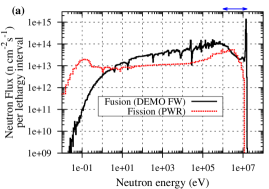
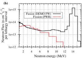
Since many of these gas-producing nuclear reactions have threshold energies, gas production and any subsequent swelling is more of a concern in fusion compared to fission because of the larger fraction of neutrons at higher energies and higher overall flux (see for example, figure 1, which compares the neutron flux per lethargy interval111lethargy interval is a commonly used measure for spectra of this type, and is equal to the natural logarithm of the ratio of a given energy-interval’s upper bound to its lower bound. as a function of energy for the 3.0 GWt [gigawatts of thermal power] DEMO concept to a 3.8 GWt fission reactor).
This paper describes the latest results from integrated studies for a conceptual design of DEMO—the demonstration fusion power-plant—combining neutron-transport simulations to define the variation in irradiation environment, inventory calculations to predict the transmutation of materials and build-up of impurities, and simple, atomic-level modeling of the consequences associated with, in this study, the production of helium-gas as an impurity. In particular, we focus on recent advances in calculation of displacements per atom (dpa) rates for neutron-irradiated materials, which are used as a measure of irradiation dose, and also revisit our earlier calculations [1] of the estimated lifetimes associated with the helium-embrittlement of grain-boundaries in light of new understanding from density-function-theory simulations.
2 Neutron transport and inventory simulations
In an earlier work [2] we focused on the transmutation response of various materials under identical first wall (FW) conditions. In the present studies we go further and investigate the response of materials as a function of position within a fusion device, with particular emphasis on how helium production rates change.
2.1 Geometry dependence of neutron flux and energy spectrum
Neutron spectra have been calculated for different regions of a recent DEMO design, proposed by CCFE in 2009 [3] (see figure 2), using the neutron-transport code MCNP [4]. The model is highly simplified, with only the major structures included, and with homogeneous material compositions. Several of the spectra calculated for this model are shown in figure 3.
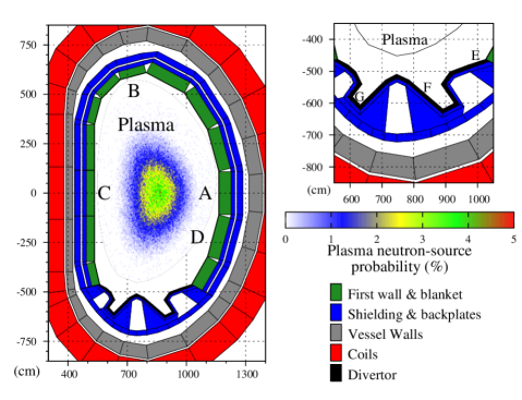
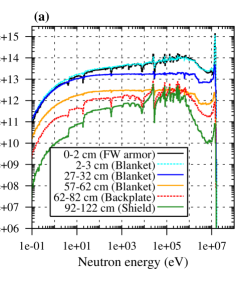
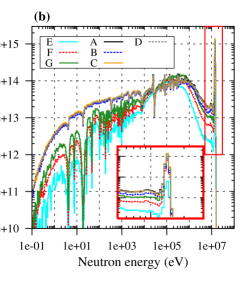
Figure 3b shows that both the energy profile and the fluxes of the neutron spectra vary dramatically as a function of distance from the plasma-facing surface into the equatorial region of the FW at A in figure 2. Not only does the neutron spectrum become heavily moderated as the distance from the plasma increases, but the total flux also falls greatly – from n cm-2 s-1 in the 2 cm FW armor at position A to n cm-2 s-1 in the final 5 cm of the blanket.
2.2 Spectral influence on transmutation and helium production
The calculated neutron spectra and total fluxes for the DEMO model have been used in the inventory code FISPACT [5] to simulate the burn-up (transmutation) of various materials relevant to design. FISPACT requires an external library of reaction cross sections and decay data, and here we have employed the 2003 version of the European Activation File (EAF) [6]. Note that, for W, we employ the self-shielding correction-factors obtained in [2] to the appropriate reactions used within FISPACT. Below we discuss the helium production rates in various fusion-relevant materials.
The gas production from iron (Fe), as the primary constituent of steels, will be a major factor in determining the lifetime of near-plasma components in fusion reactors. Chromium (Cr), which forms around 10% of the composition of the reduced activation steels being proposed for fusion application, has a very similar transmutation profile to Fe [2].
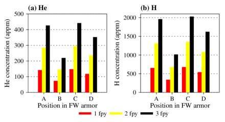
Figure 4a shows how the concentration of He produced under irradiation varies as a function of time and of position on the FW armor of the DEMO model. For comparison, figure 4b shows the equivalent hydrogen (H) production levels from Fe, which are approximately 5 times higher. The irradiation times shown here and elsewhere in this work are DEMO full-power years (fpy). In Cr, the helium production rates are 20-25% lower than in Fe (see for example figure 6), but the variations as a function of time and position are similar.
At position B in the FW, the significant drop in gas production from Fe shown in figure 4 is due to a combination of a reduced total flux ( n cm-2 s-1 vs. n cm-2 s-1 at the other positions) and a lower proportion of neutrons above the threshold energies for the gas producing reactions (e.g. , the () reaction on 56Fe, which is the main production route for He, has a threshold of approximately 3.7 MeV [6]) – see figure 3b.
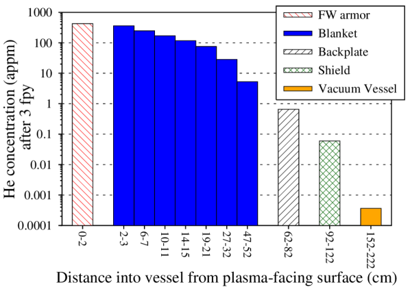
As a function of distance from the plasma-facing surface, inventory calculations reveal that the changes in the neutron irradiation conditions (figure 3) cause the He production levels to fall significantly in Fe. For example, after 3 years under DEMO full-power conditions, the He concentration is around 400 atomic parts per million (appm) in the FW armor, but has barely reached 1 appm in the 20 cm backplate behind the blanket (see figure 6).
Note that the neutron spectra calculated by MCNP do not take into account time-dependent compositional changes in materials, such as those that will take place in the blanket as the Li is depleted during tritium breeding. It is possible to investigate these processes by using an inventory code, such as FISPACT, to periodically update the material compositions in an MCNP calculation. Packer et al. [7] have recently applied such a methodology to investigate how the tritium-breeding inventory evolves in the DEMO blanket.
Tungsten (W) will be present throughout a typical reactor vessel as small concentrations in most steels and will be used in an almost pure form in the high heat-flux divertor regions due to its high melting-point, thermal-conductivity, and resistance to sputtering and erosion [8]. In many reactor designs W is also considered for the FW armor layer [9].
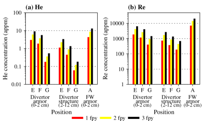
For the present DEMO model the FW armor layer is very thin, meaning that it is almost transparent to neutrons, and so it is realistic to assume that the irradiation conditions found for FW on DEMO in the previous section are very close to those that would be obtained if the FW were W instead. The results from inventory calculations (figure 7) reveal that the concentration of He produced from pure W is much lower than from Fe, but can also vary significantly, even within the same layer of the divertor.
The amount of He produced in the divertor armor (shown in figure 2) after the first 3 years of irradiation varies from 9 appm at position E to less than 1 (one) appm at G – an order of magnitude difference (figure 7a). In the divertor structure behind the armor the variation is similar, albeit at a systematically lower level. For H the variations with position are similar but the absolute concentrations are roughly twice those found for He. The higher flux in the FW armor causes the gas concentration to be somewhat greater than those observed for the divertor (see figure 7a).
Perhaps of greater significance for W are the variations in rhenium (Re) concentration between the FW armor and the divertor (figure 7b), because of the potential for the formation of -phase precipitates (with Os) [10]. After 3 years in the FW armor at A, Re reaches a concentration of around 20000 appm (2 atomic %), which is broadly in line with the previous findings in [2]. However, in the divertor armor at position E, Re only reaches a concentration of around 6400 appm (less than 1 atomic %) on the same timescale.
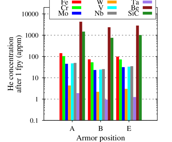
Figure 6 compares the He production from several different materials, including Fe and W, under different armor conditions after 1 fpy. It is immediately obvious that some materials, such as Be and SiC, have significantly higher production rates than the benchmark of Fe. For example, in the outboard equatorial FW armor (A in figure 2) Be, which is a key neutron moderator in tritium breeding blanket designs, produces around 4300 appm in 1 fpy, compared to the from Fe and from W. Other transition metals, such as Cr, Mo, V, and Nb have similar production levels to Fe (although Fe is the highest), while Ta has production rates as low as W.
2.3 Variation in dpa
A common method of interpretation for neutron spectra and fluxes is to convert a given set of irradiation conditions into an integrated quantity known as displacements per atom (dpa). This is particularly done to inform materials modelers and experimentalists about the irradiation dose at the atomic level. In our previous publication [1], we obtained dpa rates for different materials under various conditions predicted for the DEMO model using the modified Kinchen-Pease method of Norgett, Robinson, and Torrens (NRT) [11]. Specifically, the energy-dependent total dpa cross sections were obtained from data contained in the European Fusion File (EFF) 1.1 and processed using the NJOY [12] nuclear data processing system. Below we highlight two particular aspects of dpa evaluations, which should be carefully considered when using such data.
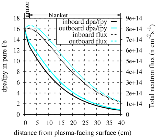
Firstly, in figure 9 we compare the variation in dpa/fpy in pure Fe to the equivalent total neutron flux as a function of distance from the plasma-facing surface into the equatorial regions of the inboard and outboard FW of the DEMO model (A and C in figure 2, respectively). In both cases, the inboard fluxes and dpa/fpy values are generally lower than the outboard values at the same distance from the plasma-facing surface. However, it is also clear that while dpa/fpy is always decreasing with increasing distance, the same is not true of the total flux, which actually increases initially with distance from the plasma due to neutron multiplication in the first few centimeters of the armor and blanket. Thus, using dpa as a measure of damage in this case would hide the fact that certain regions of the FW are experiencing a higher total flux of neutrons.
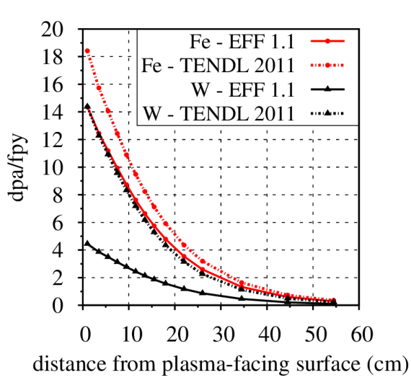
Recently the inventory code FISPACT has been extensively updated (now called FISPACT-II [13]) and, specifically, can calculate dpa rates directly using the same NRT method as before, but with the latest nuclear data libraries. Figure 9 compares our original calculations from NJOY using EFF 1.1 (used in figure 9 and in [1]) for pure Fe and W to new results obtained from FISPACT-II using the TENDL-2011 library. The graph shows the variation in dpa/fpy as a function of distance from the surface into the outboard equatorial FW at A in figure 2. It is immediately obvious that, for W in particular, there has been a dramatic change in the results. Whereas with the EFF 1.1, the dpa/fpy in pure W in the FW armor was around 4.5 dpa/fpy, with the new evaluation the values are more like 14.5 dpa/fpy – a factor of 3 increase. The change in results for Fe are less extreme, but still non-negligible. These findings highlight the need for caution when using dpa as a measure of irradiation exposure, particularly in cases where the nuclear data maybe ill-defined, for example due to a lack of supporting experimental data, and therefore subject to variation.
3 Modeling of He-induced grain-boundary embrittlement
The calculations described in the foregoing section produce quantitative estimates of the He production rates under any neutron-irradiation conditions. Using a simple model for He segregation to boundaries, we can use these results to estimate the timescales required to produce a sufficient amount of He to embrittle materials. Full details of this model are given in [1]. The model uses density-functional-theory (DFT) to calculate the energy associated with inserting He into the system, and experimentally measured surface energies to estimate the critical concentrations of He that can be accommodated at grain boundaries (GBs) before failure. Specifically, the model neglects traps and obstacles in the interior of grains, and assumes that all of the helium generated in the bulk by transmutation can migrate to the boundaries. In this sense the model is most valid in the limit of small grain size, where obstacles will have a smaller effect on the trajectory of He atoms to the GBs. We relate the critical concentration in the grain boundary plane to the critical bulk concentration via
| (1) |
where is the characteristic grain size (we can assume either cubic or spherical grains without loss of generality), and is the atomic density of the material in cm-3. Table 1 shows and values for the body-centred-cubic (bcc) transition metals, Fe, Cr, Mo, W, V, Nb, and Ta, for a small assumed grain size of 0.5 m. From equation 1 we observe that the critical bulk concentrations decrease linearly with increasing grain size, and therefore the predictions obtained from the model are very sensitive to the choice of – although, as stated above, the model is most valid in the limit of small grain size.
In [1], the critical GB concentrations were estimated by equating the surface energies to the energy of solution for a helium atom in a given material via:
| (2) |
with data taken from a database of experimental values reported in [14], and average values obtained from various publications, but specifically from [15] in the case of the bcc transition metals. However, strictly speaking, is associated with a two-step process: that of firstly creating a vacancy-like atomic configuration at the boundary, and then inserting the He atom into it. In a more realistic scenario, the vacancy-like site will already exist – either as a natural consequence of the mismatch in the orientation of neighbouring grains, or as a result of earlier irradiation damage – and so this vacancy creation energy should not be included. In effect, the GB can accommodate more He (in pre-existing spaces) than it would otherwise do in the limit of a perfectly aligned boundary with no damage (very rare).
Using this new understanding, we have performed DFT calculations to obtain the energy associated with inserting a He atom into a vacancy site . These calculations were performed using the Vienna ab-initio simulation package (VASP) [16, 17] within the generalized gradient approximation (GGA) with the Perdew-Burke-Emzerhof exchange and correlation functional [18]. Solution of the Kohn-Sham equations has been carried out self-consistently using a plane-wave basis set with an energy cutoff of 400 eV and with the projector augmented wave (PAW) pseudo-potentials. It is important to emphasise that for all the bcc transition metals, the inclusion of semi-core electrons through the use of pseudo-potentials is important for predicting accurately the defect formation energies [19, 20]. Table 1 shows the calculated values of , and the equivalent used in [1], for the bcc metals considered.
Table 1 compares the critical boundary and bulk He concentrations using the two alternative energies, as well as the approximate time taken to reach each of the values under the FW armor conditions in the outboard equatorial region of the DEMO model. As expected, the estimates are higher in the present study, leading to correspondingly higher and values. Note that in both studies, the , appear to be in reasonable agreement with experimental findings – particularly for W. Gerasimenko et al. [21] found that GBs in helium-irradiated W came apart at He concentrations of the order of – cm-2.
More important than the absolute values, which will be very sensitive to the assumptions made, particularly the grain size and omission of the effect of migration barriers, are the trends in different materials. For example, in [1] it was observed that Be, with its high He production rates, had the shortest critical lifetimes (new DFT calculations for Be have not been performed here). In table 1 the highest critical bulk concentrations and lifetimes are associated with W and Ta, primarily because He is produced at such a low level in these materials (although they also have the highest surface energies – see [1]). On the other hand, the results for Fe suggest that, even with the revised estimates, the issue of He-embrittlement of GBs could become an issue on timescales similar to the required lifetimes (5–10 years) of components in fusion reactors.
| Element | Original work in [1] | Present study | ||||||
|---|---|---|---|---|---|---|---|---|
| (FW) | (FW) | |||||||
| (eV) | (cm-2) | (appm) | (fpy) | (eV) | (cm-2) | (appm) | (fpy) | |
| Fe | 4.34 | 488.0 | 4 | 2.77 | 764.6 | 6 | ||
| Cr | 5.2 | 397.8 | 4 | 2.68 | 771.9 | 8 | ||
| Mo | 4.65 | 753.2 | 18 | 1.91 | 1833.8 | 46 | ||
| W | 4.77 | 871.5 | 326 | 1.61 | 2582.1 | 700+ | ||
| V | 4.81 | 560.5 | 12 | 2.3 | 1172.2 | 37 | ||
| Nb | 4.55 | 800.1 | 17 | 1.6 | 2275.2 | 49 | ||
| Ta | 4.82 | 841.3 | 216 | 1.69 | 2399.4 | 700+ | ||
4 Summary
This paper described the latest results from an integrated computational study for the neutron-irradiation conditions in a fusion-reactor device. The main points in this paper are:
-
1.
The MCNP calculations conducted with the conceptual CCFE design of a DEMO fusion reactor show that the neutron irradiation conditions can vary significantly as a function of position within the reactor. Even in the same component, the flux can change dramatically over short distances. As a function of distance from the plasma-facing surface of the FW, the flux drops by several orders of magnitude and the energy spectrum becomes considerably softer.
-
2.
The FISPACT-inventory calculations reveal how the variation in conditions alters the rates of production of impurities from transmutation reactions. In particular, helium concentrations fall by many orders of magnitude from the thin FW-armor layer to the outer regions of the vessel, such as the shield. In Fe, for example, the production of He of up to 140 appm per fpy in the FW-armor is likely to be significant because concentrations in the range of 400 appm are known to cause a change in the fracture behavior of neutron-irradiated steels compared to those exposed to neutrons alone [22]. However, such considerations will quickly become unimportant in regions further from the plasma, since even within the blanket the He production rate in Fe falls below 10 appm per fpy. Furthermore, in some materials, such as W, the He production levels in the bulk (as opposed to direct implantation at the plasma-facing surface) are probably too low to have any impact on component lifetime.
-
3.
An integrated quantity, such as dpa, can sometimes obscure the true variation in irradiation environment, and the sensitivity of these dpa calculations to nuclear data, as highlighted in this work, casts doubt on the suitability of dpa as the ubiquitous measure of material damage under irradiation.
-
4.
The model for He-induced embrittlement of grain-boundaries described in [1] and presented here with revised critical time estimates, while extremely simple and subject to significant assumptions (including grain size and an absence of migration barriers), suggests that He production should not be ignored when designing components for fusion devices.
While accepting the limitations of the materials modeling, the integrated approach in the present study demonstrates the potential to produce engineering relevant predictions – starting from a reactor design and using a variety of computational tools to arrive at modeling of material properties at the atomic-scale.
Acknowledgments
This work was funded by the RCUK Energy Programme under grant EP/I501045 and the European Communities under the contract of association between EURATOM and CCFE. The views and opinions expressed herein do not necessarily reflect those of the European Commission. This work was carried out within the framework of the European Fusion Development Agreement.
References
- [1] M.R. Gilbert, S.L. Dudarev, S. Zheng, L.W. Packer, and J.-Ch. Sublet, Nucl. Fus.52 (2012) 083019
- [2] M.R. Gilbert and J.-Ch. Sublet, Nucl. Fus.51 (2011) 043005
- [3] S. Zheng, Preliminary Evaluation of Decay Heat in Fusion HCPB DEMO Reactor; presented at the 4th IAEA-TM on First Generation Fusion Power Plants - Design and Technology, 8-9 June 2011, Vienna
- [4] F.B. Brown, R. Barrett, T. Booth, J. Bull, L. Cox, R. Forster, J. Goorley, R. Mosteller, S. Post, R. Prael, E. Selcow, A. Sood, and J. Sweezy, Trans. Am. Nucl. Soc.87 (2002) 273
- [5] R.A. Forrest, FISPACT-2007: User manual UKAEA FUS 534 (2007)
- [6] R.A. Forrest, The European Activation File: EAF-2003 overview UKAEA FUS 484 (2002)
- [7] L.W. Packer, R. Pampin, and S. Zheng, J. Nucl. Mater.417 (2011) 718–722
- [8] Y. Nemoto, A. Hasegawa, M. Satou, and K. Abe, J. Nucl. Mater.283–287 (2000) 1144–1147
- [9] D. Maisonnier, I. Cook, P. Sardain, L. Boccaccini, E. Bogusch, L. De Pace, R. Forrest, L. Giancarli, S. Hermsmeyer, C. Nardi, P. Norajitra, A. Pizzuto, N. Taylor, and D. Ward, Fusion Eng. Des.75–79 (2005) 1173–1179
- [10] G.A. Cottrell, J. Nucl. Mater.334 (2004) 166–168
- [11] M.J. Norgett, M.T. Robinson, and I.M. Torrens, Nucl. Eng. Des.33 (1975) 50–54
- [12] R.E. MacFarlane and D.W. Muir, The NJOY Nuclear Data Processing System: Version 91; LA-12740-M (UC-413), Los Alamos National Laboratory Report, October 1994
- [13] J.-Ch. Sublet, J.W. Eastwood, and J.G. Morgan, The FISPACT-II User Manual CCFE-R(11)11 Issue 3 (2012)
- [14] L. Vitos, A. Ruban, H. Skriver, and J. Kollár, Surf. Sci.411 (1998) 186–202
- [15] F. Willaime and C.C. Fu, Mater. Res. Soc. Symp.981 (2006) 0981–JJ05–04
- [16] G. Kresse and J. Furthmuller, Comput. Mater. Sci.6 (1996) 15
- [17] G. Kresse and J. Furthmuller, Phys. Rev. B54 (1996) 11169
- [18] P. Perdew, K. Burke, and M. Ernzerhof, Phys. Rev. Lett.77 (1996) 3865
- [19] F. Willaime, A. Satta, M. Nastar, and O. Le Bacq, Int. J. Quantum Chem.77 (2000) 927–939
- [20] D. Nguyen Manh, A.P. Horsfield, and S.L. Dudarev, Phys. Rev. B73 (2006) 020101R
- [21] V.I. Gerasimenko, I.M. Mikhaĭlovskiĭ, I.M. Neklyudov, A.A. Parkhomenko, and O.A. Velikodnaya, Tech. Phys.43 (1998) 803–808
- [22] T. Yamamoto, G.R. Odette, H. Kishimoto, J.W. Rensman, and P. Miao, J. Nucl. Mater.356 (2006) 27–49