FINAL A&T STAGES OF THE GEMINI PLANET FINDER
Abstract
The Gemini Planet Imager (GPI) is currently in its final Acceptance & Testing stages. GPI is an XAO system based on a tweeter & woofer architecture (43 & 9 actuators respectively across the pupil), with the tweeter being a Boston Michromachines MEMS device. The XAO AO system is tightly integrated with a Lyot apodizing coronagraph. Acceptance testing started in February 2013 at the University of California, Santa Cruz. A conclusive acceptance review was held in July 2013 and the instrument was found ready for shipment to the Gemini South telescope on Cerro Pachon, Chile. Commissioning at the telescope will take place by the end of 2013, matching the summer window of the southern hemisphere. According to current estimates the 3 year planet finding campaign (890 allocated hours) might discover, image, and spectroscopically analyze 20 to 40 new exo-planets. Final acceptance testing of the integrated instrument can always bring up surprises when using cold chamber and flexure rig installations. The latest developments are reported. Also, we will give an overview of GPI’s lab performance, the interplay between subsystems such as the calibration unit (CAL) with the AO bench. We report on-going optimizations on the AO controller loop to filter vibrations and last but not least achieved contrast performance applying speckle nulling. Furthermore, we will give an outlook of possible but challenging future upgrades as the implementation of a predictive controller or exchanging the conventional 48x48 SH WFS with a pyramid. With the ELT era arising, GPI will proof as a versatile and path-finding testbed for AO technologies on the next generation of ground-based telescopes.
1 Introduction
GPI belongs to the newest generation of XAO direct imaging devices that will be attached to an 8-10 m class telescope. Worldwide only a couple of instruments that are currently built or commissioned have similar capabilities, i.e. SPHERE (VLT/ESO) [1] and SCExAO (SUBARU) [7]. GPI passed pre-shipment acceptance successfully in July 2013 and arrived on Cerro Pachon in Chile in August 2013. The project is schedule-driven and aims for first light by the end of 2013. The high contrast capabilities in combination with an integral field spectrograph (IFS, 2.7”x2.7” FOV, 192x192 spaxels, 14.3 mas/spaxel) [2] allows for the detection of Jupiter mass planets as close as ” (2-3 ) from the primary as well as its classification through low resolution spectra (R in H). Eventually, astronomers can effectively study extra-solar systems in the 5-40 AU regime where the giant gas planets of our own solar system reside. This region is almost inaccessible with Doppler and transit observing techniques.
2 Contrast
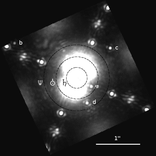
Fig. 1 shows a slice at 1.6 m of a pipeline [10] reconstructed GPI data cube with a 1 min exposure time. The data correspond to lab measurements on a calibration source as seen through a telescope simulator optical setup with a turning phase plate to simulate atmospheric turbulence. As a demonstration of GPI’s expected capabilities the four known planets of HR8799 were inserted with matching angular dimensions and its PSF peak fluxes scaled accordingly. The planets can be easily seen on a raw data cube even without using post processing techniques like ASDI. Comparable S/N would require about an hour of Keck/NIRC2 time in broadband imaging, or 5 hours to obtain similar spectral information.
The light of the primary star is suppressed via the well-established technique of apodized Lyot coronagraphy [18, 19]. Photometry and reference PSF are obtained from satellite spots located 0.52”/ off-center (where is wavelength measured in m). These satellite spots are generated by a grid of fine lines imprinted on the apodizing masks in a pupil plane following the wavefront correction surfaces. The ratio between the peak intensity of the non-coronagraphic PSF (saturating the detector in most cases) to the peak intensities of the satellite spots is approximately .
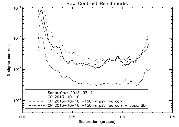
Fig. 2 shows a contrast curve as obtained at the A&T location in Santa Cruz compared with first contrast curves past shipment in the instrument laboratory at Pachon. Raw contrasts (no turbulence) as measured after fine-alignment of the instrument [17] approach between 0.5 and 1.0”. After shipment, in the telescope instrument laboratory at Cerro Pachon, the Santa Cruz benchmark raw contrast values could be recovered in applying a small focus correction. The figure shows four contrast curves. The continuous line is the raw contrast as measured during pre-shipment acceptance. The two other raw contrast curves correspond to measurements after shipment on Cerro Pachon with and without a focus correction of 150 nm P2V, also a good demonstration of the impact of low order aberrations on final performance (in this case about a factor of 2 around 0.6”). A basic SDI reduction (exploiting the fact that speckles move linearly with wavelength but real objects stay put) brings us well into the regime as demonstrated by the lowest curve. We use speckle nulling to tidy up the floor and to further lower the contrast (not shown here). Improvements depend on the precision of the used calibrations, typically up to a factor of two [16], but rather wavelength depending.
A field of ongoing research and optimization is the control of the dark hole (for GPI covering the whole FOV for the largest working wavelength) where the XAO system in combination with its specific Spatial Filter (SF) settings effectively controls high-order wavefront aberrations. Our SF is located in the focal plane of an f/64-beam. Nominally, the SF radius is expected to be which yields to 2.45 mm assuming 900 nm and using 18 cm subapertures. However, it can be difficult to find the best SF size in broadband light which leads to robust AO performance while passing through all controllable spatial frequencies. During A&T we settled on a SF size of 2.6 mm as default. Our supercontinuum light source is very red, likely one of the reasons why the loop becomes unstable for a 2.5 mm setting.
3 Loops and Alignment
| Woofer/Tweeter/TT loop (1 kHz) | |
| Optimal Fourier Controller loop, updates gains | |
| of the AO controller (0.1 Hz) | |
| Input Fold Mirror (Gemini pupil - MEMS, 1 Hz) | |
| Closed loops (continuous) | CAL pointing (via AOWFS P&C mirrors, 1 Hz) |
| CAL/LOWFS to AO WFS (0.1 Hz) | |
| [HOWFS phase tracking of fringe path length] | |
| 20 Zernikes to M1/M2 (TLC, filtered 0.1 Hz, offload 1 Hz) | |
| Offload loops (continuous) | TT/Foc (Gemini synchro bus, filtered 1 Hz, offload 10 Hz) |
| WFS P&C (MEMS/AOWFS/Apodizer/FPM) | |
| Open loop models (thermal & flexure) | CAL P&C (IFS Lyot mask/MEMS) |
| -5 to 25 ∘C, -100 to 0 deg zenith angle | SF translation stage (focal plane) |
| AlignFPM, updates WFS P&C positions | |
| (CAL SW/IS, 1 Hz) | |
| Alignment loops (occasionally) | Apodizer wheel, centering (IDL gpilib, 1 Hz) |
| no human expert judgment required | CAL-IFS P&C, centering (IDL gpilib, 1Hz) |
| AOWFS to MEMS registration (AOC/IS, 1Hz) | |
| Speckle nulling (IDL gpilib, once a minute) |
Table 1 gives an overview of the control loops [20] that are necessary to correct for atmospheric turbulence, maintain precision alignment [17] and to keep coronagraphic performance at optimum. At the core of the XAO system is the fast loop to correct atmospheric turbulence. The spatial high and low orders are controlled by a tweeter (64x64 Boston Michromachines MEMS DM, pupil spans 43 actuators) and a woofer (CILAS 11x11stacked-array DM, pupil spans 9 actuators), with a straightforward spatial splitting at the highest woofer Fourier mode . Valid woofer modes are selected by the splitting criterion which results in controlling the woofer up to the modes and . The modes and upwards to the highest mode are on the tweeter. Therefore, the maximum radial frequency on the woofer is which corresponds to a spatial period of 2.4 meters when projected onto our telescope pupil.
The woofer is mounted onto a tip/tilt (TT) stage. At 50 Hz the TT stage rejection drops by 3 db, which in practical terms means that the stage does almost all correction below 20 Hz and the woofer surface past 60 Hz, while the intermediate range is shared by both. On bright stars GPI is run at 1 kHz ( mag) but can be set to 500 Hz for fainter stars.
The gain of each Fourier mode is updated by the Optimal Fourier Controller loop (OFC) [13] every 10 sec. Precise pupil alignment on the tweeter is ensured by a slow TT control of a fold mirror at the entrance (input fold mirror), and another continuous TT loop keeps the star light centered on the Focal Plane Mask (FPM) inside the calibration unit. This is critical for coronagraphic performance and has an accuracy requirement of 4 mas.
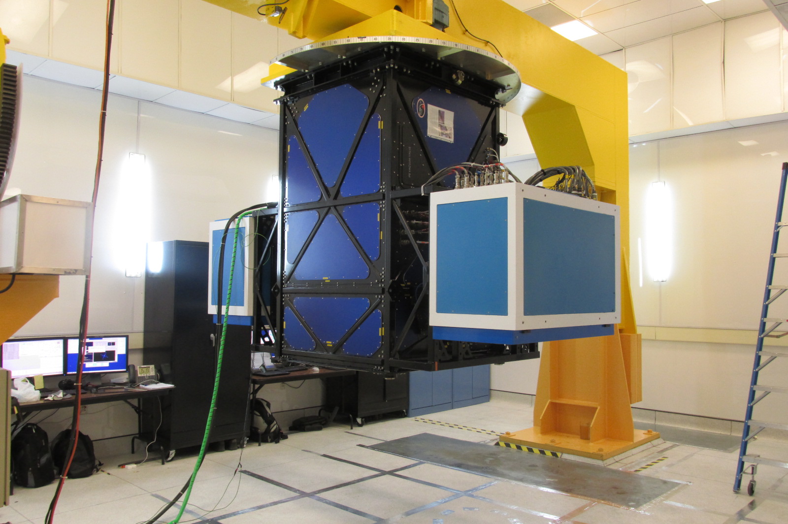
The GPI Calibration Unit (CAL) [21] is responsible for the control of non-common path aberrations (NCPA) as measured by its two WFS. The Low Order WFS (LOWFS) is a 7x7 near-infrared Shack-Hartmann, the High Order WFS (HOWFS) a Mach-Zehnder type interferometer. The reconstructed and merged wavefronts are applied as reference centroid offsets to the main AO loop once a second. For the time-being the HOWFS functionalities are de-scoped111Still a significant commissioning and development effort is required to properly combine the phases. Furthermore, internal vibration reduces the contrast of the HOWFS measured fringes more than originally expected. and thus marked with square brackets in the loop overview (Tab. 1). The first 20 Zernikes will be offloaded to the telescope mirrors M1 and M2. Thermal drifts and flexure (GPI is mounted to a Cassegrain focus) are corrected by open loop models. They keep the different pupil planes (AOWFS, MEMS, Apodizer, cold IFS Lyot mask) registered and stabilize GPI contrast performance. These open loop models have been established and verified with a dedicated flexure rig (Fig. 3) and cold chamber installations during the A&T period. Flexure tests have been repeated after shipment on Cerro Pachon.
4 Vibrations
Mitigating excess vibration is one of the most challenging tasks. The requirements are tight and contrast performance strongly depends on this. The residual TT as measured on the wavefront sensor of the AO module should be less than 4 mas RMS (for a bright star, excluding measurement noise). Obtaining this level of residual TT was challenging in the Santa Cruz A&T laboratory environment where the main excitation originated from the two closed cycle cryocoolers (CryoTel GT from Sunpower Inc.) attached to the IFS. Once mounted on the telescope, we expect the vibration environment to change significantly as new sources will be introduced such as: pumps from other instruments, fans and structural resonance frequencies excited by the wind, etc.
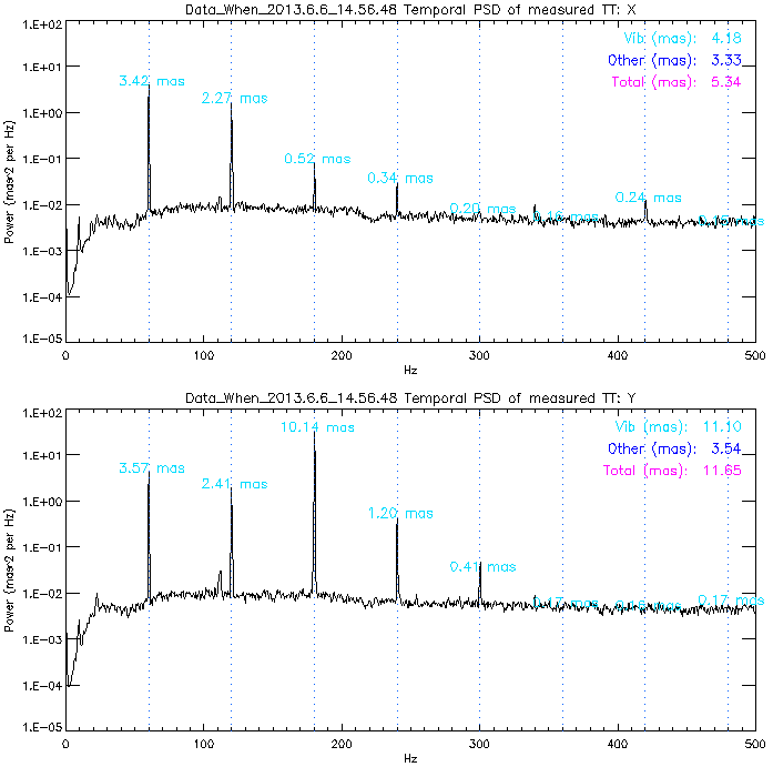
Fig. 4 shows typical temporal power spectral densities for tip and tilt (x, y) using AO telemetry data on a 15 cm phase plate222Atmospheric turbulence was simulated using a rotating phase plate [15] with cm, wind speed 2.5 m/s. If phase plate TT power deviated from Kolmogorov, the TT residuals were scaled according RMS[TT phase plate] / RMS[Kolmogorov theory].. For this measurement, the gain of the integral controller was set to 0.2, all loops were closed (TT, woofer, tweeter) and the spatial filter was adjusted to a conservative 2.8 mm. The Optimal Fourier Controller was running. Note that for bright sources, the gains of all Fourier modes are limited to 0.3 as a maximum value. The tilt (y) vibrations are significantly stronger then tip (x). This reflects the excitation geometry of the two cryocoolers and the AO WFS. The RMS sum of the vibrations in this figure surpass the specified 4 mas RMS, with significant power located at 180 Hz; well in the overshoot region of the controller.
To bring the residuals within or close to the specification, a linear-quadratic-Gaussian (LQG) controller [12] is applied to selectively reject vibration lines. These lines may also be in the overshoot region. The moving components of the Stirling cryocoolers excite at 60 Hz but as depicted in Fig. 4 its harmonics (120, 180, 240 Hz) may contain more power. Currently, we can choose between 27 different vibration filter modes (taking into account to star magnitude, wind speed, turbulence levels, controllers, SNR) to optimally adjust for the vibrational conditions. We can simultaneously correct common-path vibrations and have the ability to ignore non-common-path vibrations, if required. One challenge is to achieve a stable loop performance when lines are suppressed aggressively. R&D is still ongoing in this area.
Minor discrepancies between the oscillation frequencies of the two cryocoolers result into a beating pattern and the vibration strength varies over a period of approximately 25 min. Worse conditions prevail when the coolers’ internal components oscillate in phase. It should be mentioned Sunpower now provides a hardware mitigation of this issue via new controller boards that precisely keep the cryocoolers in opposite phase and prevent any beating. For the time being, in addition to the LQG filters, we have only implemented a passive vibration dampening by installing TVAs (Tunable Vibration Absorbers) onto the cryocoolers, from Moog CSA. This mitigation was performed just before shipment and has influenced the vibration spectrum. Its effects still need to be analyzed in more detail and the system re-optimized. An additional hardware mitigation step in the near future is the installation of tunable mass dampers (TMDs) on effective locations of the GPI structure. Up to 15 fixed mass TMDs will be installed or fewer with a customized larger TMD mass. No active vibration control using external hardware is foreseen.
5 Upgrades: Predictive Control & a Pyramid WFS
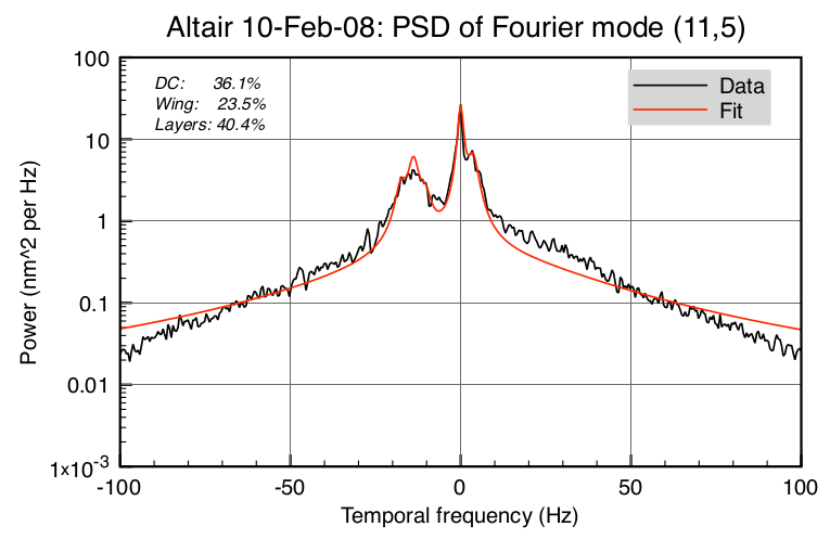
The upcoming E-ELT era will challenge current AO technologies. Despite GPI becoming a facility instrument, there is significant interest to improve and study the performance of XAO high-contrast systems using new or recent technologies, such as predictive control or Pyramid wavefront sensing. From the observatory’s standpoint, any impact on science operations has to be avoided or minimized. Therefore, an upgrade of GPI to a predictive control scheme [14] is particularly promising since it involves no extra hardware and exploits the frozen flow hypothesis for atmospheric turbulence [11]. This would increase GPI limiting magnitude by approximately 1 magnitude resulting in a significant increase the available scientific targets.
Here, we briefly describe the basic recipe [14]. The valid actuators in the pupil are mapped (NxN grid) and the actuator signals are converted to (complex-valued) modal Fourier coefficients (DFT). The DM influence function is removed and the actuator signal converted to a phase in nm. The PSD is calculated for each time series of the complex-valued modal coefficients. We then employ the property that a pure translation of Fourier modes produces a peak in temporal frequencies set by the spatial frequency and the wind velocity :
| (1) |
An example of corresponding, “frozen flow peaks,” is shown in Fig. 5. However, one must be certain that the frozen flow is indeed detected and this effect is not due to vibration or other unknown phenomena. This is accomplished by using the frequencies found in all Fourier modes to calculate the likelihood for a frozen flow layer using the percentage of modes belonging to a detected peak (e.g. to +/- 0.75 Hz). This method is very robust at rejecting false positives. For example, vibrations and aliasing have a likelihood below 5%. A corresponding likelihood map is displayed in Fig. 6.

Pyramid wavefront sensing has been proven to optimally suit XAO and high-contrast needs [6, 5, 3, 4]. Upgrading the GPI WFS to a pyramid design was envisioned many years ago, however, no practical steps have been undertaken to facilitate its implementation. Space and weight limitations imposed by GPI being at a Cassegrain focus provide challenging restrictions. Therefore, installing pyramid wavefront sensing capabilities in the near future is not possible without disrupting science operations. But developers never stop dreaming, and it is conceivable that after the completion of the GPI planet finding campaign, the current AO WFS could be replaced by a pyramid during a longer shut down. If installed, this would improve the limiting magnitude of targets and further increase coronagraphic performance.
References
- [1] J.-L. Beuzit, M. Feldt, K. Dohlen, D. Mouillet, P. Puget, F. Wildi, L. Abe, J. Antichi, A. Baruffolo, P. Baudoz, A. Boccaletti, M. Carbillet, J. Charton, R. Claudi, M. Downing, C. Fabron, P. Feautrier, E. Fedrigo, T. Fusco, J.-L. Gach, R. Gratton, T. Henning, N. Hubin, F. Joos, M. Kasper, M. Langlois, R. Lenzen, C. Moutou, A. Pavlov, C. Petit, J. Pragt, P. Rabou, F. Rigal, R. Roelfsema, G. Rousset, M. Saisse, H.-M. Schmid, E. Stadler, C. Thalmann, M. Turatto, S. Udry, F. Vakili, and R. Waters. SPHERE: a planet finder instrument for the VLT. In Ground-based and Airborne Instrumentation for Astronomy II, volume 7014 of Proc. SPIE, Aug. 2008.
- [2] J. K. Chilcote, J. E. Larkin, J. Maire, M. D. Perrin, M. P. Fitzgerald, R. Doyon, S. Thibault, B. Bauman, B. A. Macintosh, J. R. Graham, and L. Saddlemyer. Performance of the integral field spectrograph for the Gemini Planet Imager. In Ground-based and Airborne Instrumentation for Astronomy IV, volume 8446 of Proc. SPIE, Sept. 2012.
- [3] L. M. Close, J. R. Males, K. Morzinski, D. Kopon, K. Follette, T. J. Rodigas, P. Hinz, Y.-L. Wu, A. Puglisi, S. Esposito, A. Riccardi, E. Pinna, M. Xompero, R. Briguglio, A. Uomoto, and T. Hare. Diffraction-limited Visible Light Images of Orion Trapezium Cluster with the Magellan Adaptive Secondary Adaptive Optics System (MagAO). ApJ, 774:94, Sept. 2013.
- [4] L. M. Close, A. Puglisi, J. R. Males, C. Arcidiacono, A. Skemer, J. C. Guerra, L. Busoni, G. Brusa, E. Pinna, D. L. Miller, A. Riccardi, D. W. McCarthy, M. Xompero, C. Kulesa, F. Quiros-Pacheco, J. Argomedo, J. Brynnel, S. Esposito, F. Mannucci, K. Boutsia, L. Fini, D. J. Thompson, J. M. Hill, C. E. Woodward, R. Briguglio, T. J. Rodigas, R. Briguglio, P. Stefanini, G. Agapito, P. Hinz, K. Follette, and R. Green. High-resolution Images of Orbital Motion in the Orion Trapezium Cluster with the LBT AO System. ApJ, 749:180, Apr. 2012.
- [5] S. Esposito, D. Mesa, A. Skemer, C. Arcidiacono, R. U. Claudi, S. Desidera, R. Gratton, F. Mannucci, F. Marzari, E. Masciadri, L. Close, P. Hinz, C. Kulesa, D. McCarthy, J. Males, G. Agapito, J. Argomedo, K. Boutsia, R. Briguglio, G. Brusa, L. Busoni, G. Cresci, L. Fini, A. Fontana, J. C. Guerra, J. M. Hill, D. Miller, D. Paris, E. Pinna, A. Puglisi, F. Quiros-Pacheco, A. Riccardi, P. Stefanini, V. Testa, M. Xompero, and C. Woodward. LBT observations of the HR 8799 planetary system. First detection of HR 8799e in H band. Astron. Astrophys., 549:A52, Jan. 2013.
- [6] O. Guyon. Limits of Adaptive Optics for High-Contrast Imaging. Astrophy. J., 629:592–614, Aug. 2005.
- [7] N. Jovanovic, O. Guyon, F. martinache, C. Clergeon, G. Singh, S. Vievard, T. Kudo, V. Garrel, B. Norris, P. Tuthill, P. Stewart, E. huby, G. Perrin, and S. Lacour. SCExAO as a precursor to an ELT exoplanet direct imaging instrument. this conference, Oct. 2013.
- [8] B. A. Macintosh, A. Anthony, J. Atwood, N. Barriga, B. Bauman, K. Caputa, J. Chilcote, D. Dillon, R. Doyon, J. Dunn, D. T. Gavel, R. Galvez, S. J. Goodsell, J. R. Graham, M. Hartung, J. Isaacs, D. Kerley, Q. Konopacky, K. Labrie, J. E. Larkin, J. Maire, C. Marois, M. Millar-Blanchaer, A. Nunez, B. R. Oppenheimer, D. W. Palmer, J. Pazder, M. Perrin, L. A. Poyneer, C. Quirez, F. Rantakyro, V. Reshtov, L. Saddlemyer, N. Sadakuni, D. Savransky, A. Sivaramakrishnan, M. Smith, R. Soummer, S. Thomas, J. K. Wallace, J. Weiss, and S. Wiktorowicz. The Gemini Planet Imager: integration and status. In Ground-based and Airborne Instrumentation for Astronomy IV, volume 8446 of Proc. SPIE, Sept. 2012.
- [9] B. A. Macintosh, J. R. Graham, D. W. Palmer, R. Doyon, J. Dunn, D. T. Gavel, J. Larkin, B. Oppenheimer, L. Saddlemyer, A. Sivaramakrishnan, J. K. Wallace, B. Bauman, D. A. Erickson, C. Marois, L. A. Poyneer, and R. Soummer. The Gemini Planet Imager: from science to design to construction. In Adaptive Optics Systems, volume 7015 of Proc. SPIE, July 2008.
- [10] J. Maire, M. D. Perrin, R. Doyon, J. Chilcote, J. E. Larkin, J. L. Weiss, C. Marois, Q. M. Konopacky, M. Millar-Blanchaer, J. R. Graham, J. Dunn, R. Galicher, F. Marchis, S. J. Wiktorowicz, K. Labrie, S. J. Thomas, S. J. Goodsell, F. T. Rantakyro, D. W. Palmer, and B. A. Macintosh. Test results for the Gemini Planet Imager data reduction pipeline. In Software and Cyberinfrastructure for Astronomy II, volume 8451 of Proc. SPIE, Sept. 2012.
- [11] L. Poyneer, M. van Dam, and J.-P. Véran. Experimental verification of the frozen flow atmospheric turbulence assumption with use of astronomical adaptive optics telemetry. Journal of the Optical Society of America A, 26:833, Mar. 2009.
- [12] L. Poyneer and J.-P. Véran. Kalman filtering to suppress spurious signals in adaptive optics control. Journal of the Optical Society of America A, 27:A223–A234, 2010.
- [13] L. A. Poyneer and B. A. Macintosh. Optimal Fourier control performance and speckle behavior in high-contrast imaging with adaptive optics. Optics Express, 14:7499, Aug. 2006.
- [14] L. A. Poyneer, B. A. Macintosh, and J.-P. Véran. Fourier transform wavefront control with adaptive prediction of the atmosphere. Journal of the Optical Society of America A, 24:2645–2660, 2007.
- [15] R. Rampy, D. Gavel, D. Dillon, and S. Thomas. Production of phase screens for simulation of atmospheric turbulence. Appl. Opt., 51:8769, Dec. 2012.
- [16] D. Savransky, B. A. Macintosh, S. J. Thomas, L. A. Poyneer, D. W. Palmer, R. J. De Rosa, and M. Hartung. Focal plane wavefront sensing and control for ground-based imaging. In Society of Photo-Optical Instrumentation Engineers (SPIE) Conference Series, volume 8447 of Adaptive Optics Systems II, July 2012.
- [17] D. Savransky, S. J. Thomas, L. A. Poyneer, and B. A. Macintosh. Computer vision applications for coronagraphic optical alignment and image processing. Appl. Opt., 52:3394, May 2013.
- [18] R. Soummer. Apodized Pupil Lyot Coronagraphs for Arbitrary Telescope Apertures. ApJ Letter, 618:L161–L164, Jan. 2005.
- [19] R. Soummer, A. Sivaramakrishnan, B. R. Oppenheimer, R. Roberts, D. Brenner, A. Carlotti, L. Pueyo, B. Macintosh, B. Bauman, L. Saddlemyer, D. Palmer, D. Erickson, C. Dorrer, K. Caputa, C. Marois, K. Wallace, E. Griffiths, and J. Mey. The Gemini Planet Imager coronagraph testbed. In Techniques and Instrumentation for Detection of Exoplanets IV, volume 7440 of Proc. SPIE, Aug. 2009.
- [20] S. Thomas, L. Poyneer, D. Savransky, B. Macintosh, M. Hartung, D. Dillon, D. Gavel, J. Dunn, K. Wallace, D. Palmer, and R. De Rosa. Wavefront sensing and correction with the Gemini Planet Imager. In Adaptive Optics Systems II, volume 8447 of Proc. SPIE, July 2012.
- [21] J. K. Wallace, R. Burruss, L. Pueyo, R. Soummer, C. Shelton, R. Bartos, F. Fregoso, B. Nemati, P. Best, and J. Angione. The Gemini Planet Imager calibration testbed. In Techniques and Instrumentation for Detection of Exoplanets IV, volume 7440 of Proc. SPIE, Aug. 2009.