Superconducting complementary metasurfaces for THz ultrastrong light-matter coupling
Abstract
A superconducting metasurface operating in the THz range and based on the complementary metamaterial approach is discussed. Experimental measurements as a function of temperature and magnetic field display a modulation of the metasurface with a change in transmission amplitude and frequency of the resonant features. Such a metasurface is successively used as a resonator for a cavity quantum electrodynamic experiment displaying ultrastrong coupling to the cyclotron transition of a 2DEG. A finite element modeling is developed and its results are in good agreement with the experimental data. In this system a normalized coupling ratio of is measured and a clear modulation of the polaritonic states as a function of the temperature is observed.
1 Introduction: ultrastrong light-matter coupling with THz metasurfaces and 2-dimensional electron gas
Light-matter interaction phenomena lie at the heart of quantum photonics [1]. Recently, there has been a considerable progress in the understanding and in the realization of light-matter coupling experiments covering a large portion of the electromagnetic spectrum, from the visible to the microwave range. When considering low frequency photons, such experiments can benefit from the excellent characteristics of superconducting cavities which ensure low loss rates allowing observation and manipulation of polaritonic systems, from atomic physics to solid state. [2, 3]
Light-matter coupling physics in solid state system has been recently approaching a new regime, called ultrastrong coupling [4, 5] , where the Rabi frequency of the system is comparable to the bare excitation frequency of the matter part . Semiconductor-based systems operating in the Mid-IR [6, 7, 8] and THz [9, 10, 11] are particularly attractive for the study of this peculiar regime because very large dipole moments can be achieved and the system can benefit from the enhancement of the light-matter coupling by deriving form the simultaneous coupling of N electrons with the same photonic mode of the cavity. We recently demonstrated that the cyclotron transition of a 2-dimensional electron gas (2DEG) coupled to a metasurface of subwavelength split-ring resonators can attain the ultrastrong coupling regime showing record high values of the normalized light-matter coupling ratio [12, 13]. This system is very promising for probing the ultimate limits of the ultrastrong light-matter coupling since the coupling ratio scales with the filling factor of the 2DEG. This means that, as long as the cyclotron transition can be resolved, the experiments can be scaled down in frequency achieving coupling ratios in principle much higher than unity [14].
The ultrastrong coupling regime has been predicted to display intriguing and peculiar quantum electrodynamics features: Casimir-like [15] squeezed vacuum photons upon either non-adiabatic change or periodic modulation in the coupling energy [4], non-classical radiation from chaotic sources [16], ultrafast switchable coupling [17], spontaneous conversion from virtual to real photons [18]. The paper is organized as follows: in Sec.2 we present the metasuface design and its fabrication. In Secs.2.1 and 2.2 we analyze the behavior of the metasurface as a function of the temperature and of the applied magnetic field respectively, together with finite element modeling. In Sec.3 we then present the measurements were the Nb metasurface is strongly coupled to the cyclotron transition of a 2DEG.
2 The metamaterial cavity: fabrication, experimental results and modeling
In our previous experiments [12, 13], we employed metasurfaces of split-ring resonators that, when probed in transmission, show an absorption dip at the resonant frequency of the LC mode. The characteristic anticrossing behavior of the polaritonic system is probed by scanning the magnetic field. This provides a linear tuning of the cyclotron energy. With such experimental arrangement we have observed three absorption features [12, 13]: two are related to the light-matter coupled system and the third middle peak is the cyclotron signal coming from the material which lies in between the resonators. This cyclotron signal is only weakly coupled to the metasurface and follows the expected linear dispersion for a cyclotron transition . In order to observe with greater detail the spectroscopic features of the polaritonic branches, we now change the configuration of the metamaterial cavity and we employ a complementary cavity.
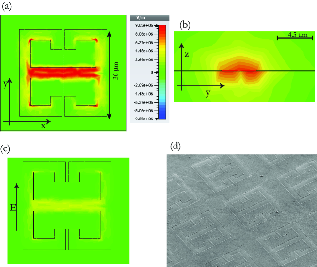
As already shown in several papers [19, 20] the complementary metamaterial is obtained by exchanging the roles of the vacuum areas and of the metals composing the metasurface. The resulting metasurface is constituted of a metallic sheet with openings with the shapes of the resonators. When excited with an electric field complementary to the one used in the case of the direct metamaterial (i.e. along the y axis, perpendicular to the central gap as in Fig.1(c)), the resonator will display a transmission spectrum which is complementary to the one shown by the split ring resonators.
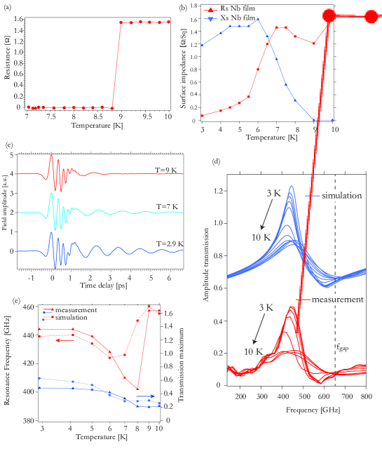
The intriguing quantum optical predictions for an ultrastrongly coupled system rely on a non-adiabatic modulation [4, 7, 15] of the system’s parameters; in our case on timescale faster than the Rabi frequency of the system (100-400 GHz). The fabrication of a superconducting cavity offers an interesting opportunity in this direction, since the cavity characteristics strongly depend on the state (superconducting or normal) in which the material operates. On the other hand, even if in our case the quality factor of the split-ring resonator is radiatively limited, the presence of the superconductor will mitigate the ohmic losses yielding a longer polariton coherence time. In the last few years many examples of superconducting GHz and THz metamaterials have been presented, both using BCS superconductors like Nb and NbN [21, 22, 23], or dealing with hight Tc superconductors [24]. For our cavity we chose Nb, which is a well-known superconducting material widely employed in THz science. The niobium film of the resonators, about 100 nm thick, is deposited by dc-magnetron sputtering both on a semi insulating (SI) GaAs (for the control sample) and on a sample containing a triangular well 2DEG (for the strong-coupling experiment). On top of the Nb film we spun an electronic resist (Polymethyl Methacrylate, positive tone electronic resist) and the pattern was defined by the direct writing with the electron beam lithography. Successively, the niobium is selectively removed by means of a dry reactive ion etching. A scanning electron microscope picture of the fabricated devices is presented in Fig.1(d). The Nb film has a critical temperature Tc of 8.7 K, as results from DC resistance measurements reported in Fig.2(a). From this Tc value we can infer a gap value of meV which corresponds to GHz [25].
In Fig. 1(a) we report the design of our resonator (very similar to the one reported in Ref. [20] ) and the in-plane electric field distribution (which is the one relevant for the inter-Landau level coupling) for the LC resonance when the superconductor is in the superconducting state. More details about the modeling of the metasurface wil be given in Sec.2.1. The capacitor, where the majority of the electric field is concentrated, is now constituted by the central section of the resonator of width 4.5 . The effective volume of the cavity in this case can be estimated as m3 which yields a ratio of .
In Fig. 1(c) we report the in-plane electric field distribution simulated with the superconductor in the normal state: the electric field enhancement results approximately one half than the one simulated in the superconducting case.
2.1 THz metasurface characteristics as a function of the temperature
The complementary metasurface, first fabricated on SI GaAs, is then probed with THz-Time Domain Spectroscopy (TDS) in a range of temperatures above and below Tc. The experimental setup employed in this paper is based on a THz-TDS system coupled to a split-coul superconducting magnet and is described in detail in Refs. [12, 13] As visible from Fig. 2(c,d,e), a clear change in the metasurface Q factor and a shift of the resonance frequency is observed between 8 K an 9 K, as already observed in direct metamaterials fabricated with other kind of superconductors [24]. The deduced high-frequency Tc of 8.5 K is in good agreement with the DC value and the one found in similar structures [22].
The observed behavior of the superconducting complementary metasurface can be explained by considering the complex conductivity of the metasurface and the LC nature of the resonance. For a superconductor like Nb in the normal state (above Tc) the conductivity is essentially real and, in thin films has been measured in the range of S/m [25]. Below , is mainly complex and frequency dependent: the complex part displays low values in proximity of the superconducting gap frequency . In order to model the system we can proceed following Chen et al,[24] by considering the surface impedance of a superconducting film with a thickness d can be expressed as where is the complex conductivity. The resistive part and the reactive part can then be connected to the parameters of the resonator seen as an RLC circuit.
Still along the analysis presented in Ref.[24] we can express the resonance of the LC mode in the following way:
| (1) |
where is the geometrical value of the inductance, represents the kinetic inductance due to the imaginary part of the conductivity and R is the resistance of the circuit. When the temperature is above , the value of is extremely small and the resistance R is inversely proportional to the real part of the Nb conductivity. The shift of the resonance for temperatures just below is mainly due to the emergence of the imaginary part of the conductivity which effectively introduces the kinetic inductance of the Cooper pairs. Across the superconducting transition , we will have the value of R that will change due to the change of the real part of the conductivity and the reactive part which will become relevant introducing a supplementary term L which effectively lowers the frequency. This explains the redshift of the resonance between 9 K and 7 K. Further reduction of the temperature increases the conductivity, thus reducing the resistance. This is reflected in two aspects, a narrowing of the resonance due to reduced dissipation and a blue shift due to the reduction of R which restores an higher value for the resonance frequency .
We measured the complex conductivity of the employed 100 nm thick Nb unstructured film as a function of the temperature with THz-TDS. Successively we calculated the complex surface impedance and we extracted the values at the resonant frequency f=440 GHz. These values are reported in Fig.2(b) and then used to perform the 3D calculation. As visible from the Fig.2(d,e) the experimental results are well reproduced by the 3D modeling performed with CST microwave studio using a surface impedance model for the superconductor. The small discrepancy between the simulated amplitude transmission and the measured one has already been observed in similar experiments [24] and can be ascribed to different causes. We believe the main reason is that the values for the complex conductivity are considered as frequency-independent in the simulations: this is not true and they present quite large variations especially when approaching the gap frequency: our resonator is in fact operating slightly below the gap ( GHz) and this simplification can explain the semi-quantitative agreement between simulations and experiments. It is remarkable that no relevant features are observed in the metamaterial spectra in correspondence and above of the gap frequency fgap.
2.2 THz metasurface characteristics as a function of perpendicular magnetic field
In order to model the complete system when the 2DEG is coupled to the resonator and measured as a function of the magnetic field we need then study and model the resonator behavior as a function of the applied magnetic field. We now analyze the data of the superconducting metasurface at a temperature of 2.9 K subjected to a perpendicular magnetic field of increasing strength. The measured transmission spectra are reported in Fig.3(a)(red traces). The application of a perpendicular magnetic field leads to a steady decrease of the transmission at resonance and a slight redshift until a field value of 1.5 T. At this point a transition occurs and the resonator linewidth broadens considerably together with a blueshift of the resonant frequency: such a shape and both the transmission value and the resonant frequency stay constant until high values of the applied magnetic field (see Fig. 3 (c)).
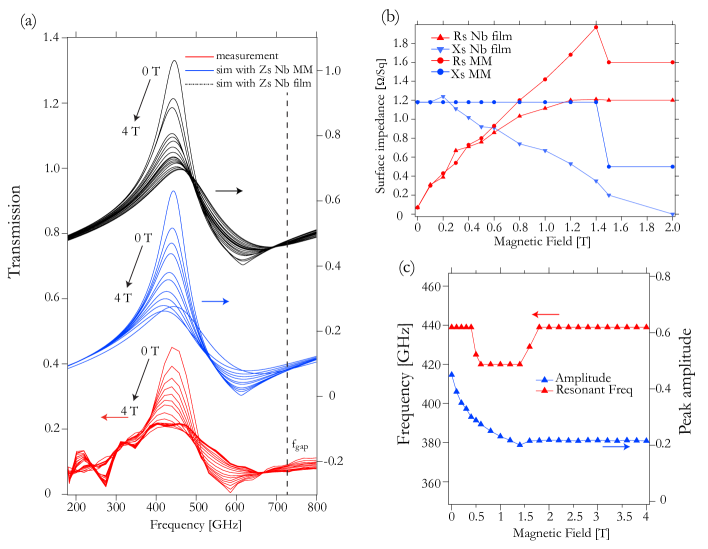
It is known that in a type II superconductor such as Nb, the application of a perpendicular magnetic field produces current vortices in the sample which surround regions of normal state conductivity, where the magnetic field can penetrate the sample [26, 27, 28]. At the same time, there is an increasing portion of the sample which presents normal state for Nb, and these two effect enter in a non trivial way into the expression for the surface impedance. The plain Nb film was measured this time as a function of the magnetic field at a constant temperature of T=2.9 K. The extracted surface impedance at 440 GHz is reported in Fig.3 (b) and is used to model the resonator. The results are reported in Fig.3(a) as black lines: the change in transmittance is well reproduced but the frequency shift shows an opposite behavior. In order to have a numerical model to use in the simulation of the complete system, we then deduce effective values for the metasurface complex impedance parameter which show good agreement with the experimental data. These parameters are reported in Fig.3 (b) and labeled as Rs MM and Xs MM since are effective values for the metamaterial. The results of the simulations with such parameters are reported in Fig.3 (a)(blue lines). In order to reproduce the experimental results, we need to keep the reactance value Xs constant until the critical field value of 1.5 T and change only the resistive part. This behavior, which differs from what experimentally observed with the measurements of the Nb film, can be qualitatively explained by the presence of a structured surface on the micrometric scale (the metamaterial itself) that alters the behavior and the vortex formation,[29] leading, in the case of the metasurface, to a different evolution of the surface impedance as a function of the applied magnetic field.
3 Ultrastrong coupling with superconducting metasurface
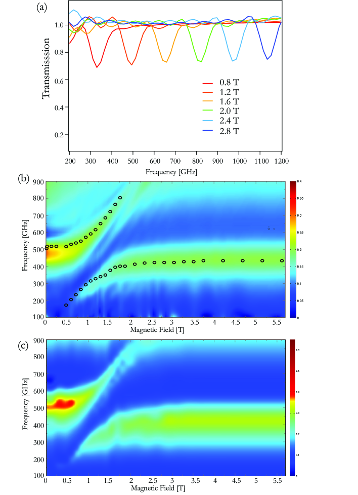
Now we consider the complete system and we analyze the measurements where the superconducting metasurface is strongly coupled to the Landau levels of the 2DEG: we use a triangular quantum well of sheet carrier density cm-2 (measured with Hall bars) with the channel lying 100 nm below the surface. An example of the inter-Landau level transition, or cyclotron resonance, that we observe from the triangular 2DEG without any metasurface is reported in Fig.4(a).
The resonator we use displays field enhancement also in the TM polarization (electric field perpendicular to the semiconductor surface), which has been used to observe light-matter coupling with intersubband transitions [30]. From measurements (not shown) of the 2DEG alone in a tilted magnetic field [31] we deduce an energy separation between the first two subbbands of our triangular quantum well of at least 3 THz, so the ISB does not couple to the TM field of our resonator for the LC mode.
In Fig.4(b) is visible a color plot of a transmission experiment carried out at 2.9 K. Clear anticrossing between upper and lower branch is observed and we can measure a normalized coupling ratio which makes the system operating in the ultrastrong light-matter coupling regime. Due to the use of a complementary metasurface the polaritonic branches are especially clear because the cyclotron signal is not present in between the two branches. A transmission maximum parallel to the cyclotron dispersion is observable starting from 1.4 T and a frequency of 0.5 THz and is due to the coupling of the second mode of the resonator to the cyclotron resonance. We can model then the complete system using, as cavity parameters, the ones obtained with the measurements described in the previous paragraph and labeled as Rs MM and XsMM. As visible from the color plot of Fig. 4(c), the experimental data is well reproduced by the numerical modeling. For convenience, the transmission peaks deduced from the simulations have been reported on the experimental data of Fig.4(b) as black circles. The model is able to reproduce also weak features as the coupling with the second mode of the cavity which is clearly visible as a weak maximum of transmission both in the direct measurements and in the simulation. The 2DEG can be experimentally characterized by a complex conductivity, measured again by THz-TDS as in Ref. [32]. From the conductivity we can deduce the frequency dependent complex dielectric constant . Such expression can be used to perform finite element simulations and contains all the physics of the system in a semiclassical description.
The 2DEG is modeled by having an effective thickness of 200 nm (the value resulting from band structure calculations is 20 nm, which is too small to yield consistent results with the 3D FE solver). As already observed in our previous experiments [12, 13], the bare resonator frequency is blue-shifted to when the cavity is loaded with the 2DEG electrons which are free to move in the x-y plane without applied magnetic field. The magnitude of the shift is directly related to the normalized coupling strength and is due to the quadratic terms of the light-matter Hamiltonian [4, 14]. As discussed also in Refs. [10, 33, 8, 9] the presence of this polaritonic gap is a signature of the ultrastrong light-matter coupling regime. By taking the value at B=0 for the upper polariton branch and the value for for the lower polariton branch as expressed from the solution of the secular equation of Ref.[14] we obtain the following equation that relates the normalized light-matter coupling ratio to the normalized frequency gap :
| (2) |
If we take the experimental data of the shift of the resonance frequency at B=0 T and we compute the expected light-matter coupling ratio we find 0.28 which is in excellent agreement with the value 0.27 directly deduced from the anticrossing splitting . We notice that the shift is also quantitatively reproduced by the finite element model (the value of the resonance at B=0 in Fig.4(b) is higher than the one at B=5.7 T ). This happens because the conductivity model used for the 2DEG yields the correct description also for , where the dielectric constant value is lowered by the free carrier contribution, which generates the blue shift of the cavity mode observed at B=0. On the other limit, for high values of the magnetic field, the cavity resonant frequency assumes the value measured on the control sample (SI GaAs substrate), were no free electrons are present.
The value of the light-matter coupling ratio is independent from the material used to fabricate the cavities as it depends only on the geometry of the metamaterial elements. We performed similar strong coupling measurements on standard Au cavities of identical design on the same heterostructure and we obtain =0.27, in excellent agreement with what found with Nb cavities. A comparison with the respective direct metamaterial will be carried out elsewhere [34]. The cavity design of the present work is the complementary version of what published in Ref. [13]: in that case the normalized coupling ratio was slightly higher () because the volume of the cavity for the direct metasurface is smaller, as well as the mode extension in the growth direction which affects the coupling strength.
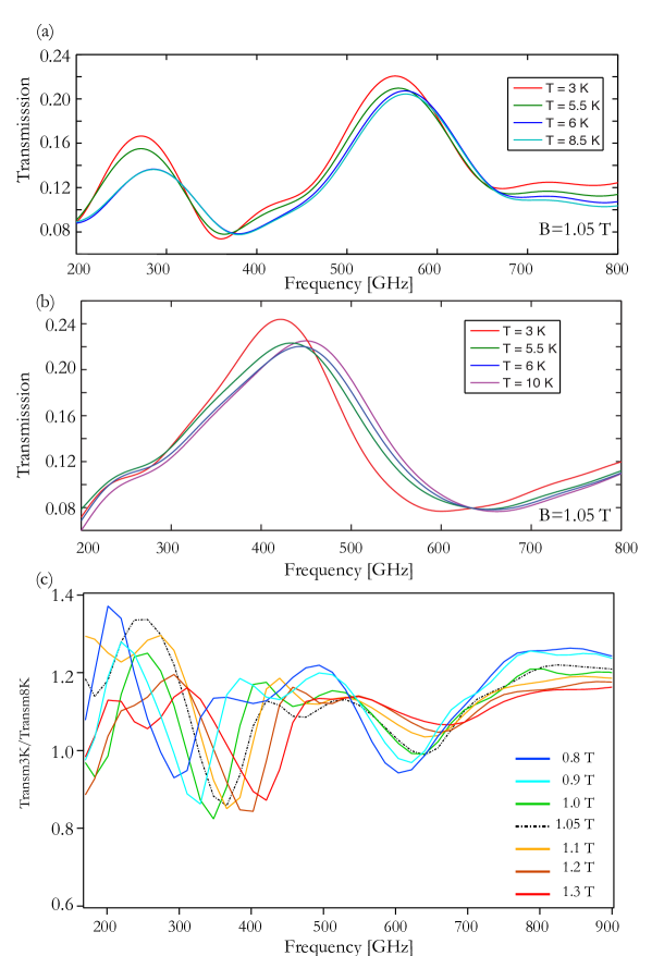
The possibility to modulate the ultrastrong coupling regime by changing the characteristics of the cavity is illustrated in Fig.5(a) where we show a series of transmission spectra taken at the resonant field B=1.05 T by changing the sample’s temperature from below to above Tc. We can clearly observe a modulation both in intensity and in frequency of both polariton peaks, which reflects what observed in the same conditions for the cavity only, reported in Fig.5(b). In order to better analyze the impact of the superconducting transition on the ultrastrongly coupled system, we plot in Fig.5(c) the ratio between the transmission spectra at 3.5K to the ones at 8 K (above the superconducting transition) for magnetic fields values in the range 0.8-1.3 T. As visible from the graph, the relative change of both polaritonic branches is significant, reaching 35 % for the lower branch and 20 % for the upper branch. It is interesting to note the different behavior of the lower and upper branches as a function of the applied field. The relative change for the upper branch steadily decreases to zero as long as the magnetic field is increased. On the contrary, the relative change of the lower branch reaches a maximum for the resonant value of B=1.05 T but never goes below 15 % in the range of magnetic fields 0.8-1.3 T. This can be explained by the fact that the upper branch becomes more and more matter-like and then the impact of the temperature change is much weaker compared to the cavity. The lower branch, on the contrary, is becoming more cavity-like and thus is more affected by the cavity change.
4 Conclusions
In conclusion we presented light-matter coupling experiments in the THz range employing complementary superconducting metasurfaces. The system operates in the ultrastrong coupling regime and the presence of the superconducting cavity allows the modulation of the resonant frequency and of the quality factor of the resonator. As already shown in literature, the superconducting metasurface can be modulated in a an ultrafast way, on a sub picosecond timescale [35]. In future work we will leverage on that aspect and realize non-adiabatic experiments in the ultra strong coupling regime in our magnetopolaritonic system.
References
References
- [1] S. Haroche and J. Raimond. Exploring the quantum. Oxford University Press, 2006.
- [2] J. Raimond, M. Brune, and S. Haroche. Colloquium: Manipulating quantum entanglement with atoms and photons in a cavity. Rev. Mod. Phys., 73:565, 2001.
- [3] A. Wallraff, D. I. Schuster, A. Blais, L. Frunzio, R.-S. Huang, J. Majer, S. Kumar, S. M. Girvin, and R. J. Schoelkopf. Strong coupling of a single photon to a superconducting qubit using circuit quantum electrodynamics. Nature, 431:162, 2004.
- [4] C. Ciuti, G. Bastard, and I. Carusotto. Quantum vacuum properties of the intersubband cavity polariton field . Phys. Rev. B, 72:115303–1–115303–9, 2005.
- [5] T. Niemczyk, F. Deppe, H. Huebl, E. P. Menzel, F. Hocke, M. J. Schwarz, J. J. Garcia-Ripoll, D. Zueco, T. H mmer, E. Solano, A. Mar, and R. Gross. Circuit quantum electrodynamics in the ultrastrong-coupling regime. Nature Physics, 6:772 776, 2010.
- [6] Aji Anappara, Simone De Liberato, Alessandro Tredicucci, Cristiano Ciuti, Giorgio Biasiol, Lucia Sorba, and Fabio Beltram. Signatures of the ultrastrong light-matter coupling regime. Phys. Rev. B, 79(20):201303, May 2009.
- [7] G. Guenter, A.A.Anappara, J.Hees, A.Sell, G. Biasiol, L. Sorba, S. De Liberato, C. Ciuti, A. Tredicucci, A. Leitenstorfer, and R. Huber. Sub-cycle switch-on of ultrastrong light-matter interaction. Nature, 458(7235):178–181, MAR 12 2009.
- [8] A. Delteil, A. Vasanelli, Y. Todorov, C. Feuillet Palma, M. Renaudat St-Jean, G. Beaudoin, I. Sagnes, and C. Sirtori. Charge-induced coherence between intersubband plasmons in a quantum structure. Phys. Rev. Lett., 109:246808, 2012.
- [9] M. Geiser, F. Castellano, G. Scalari, M. Beck, L. Nevou, and J. Faist. Ultrastrong coupling regime and plasmon polaritons in parabolic semiconductor quantum wells. Phys. Rev. Lett., 108:106402, 2012.
- [10] Y. Todorov, A. M. Andrews, R. Colombelli, S. De Liberato, C. Ciuti, P. Klang, G. Strasser, and C. Sirtori. Ultrastrong light-matter coupling regime with polariton dots. Phys. Rev. Lett., 105(19):196402, Nov 2010.
- [11] V. M. Muravev, P. A. Gusikhin, I. V. Andreev, and I. V. Kukushkin. Ultrastrong coupling of high-frequency two-dimensional cyclotron plasma mode with a cavity photon. Phys. Rev. B, 87:045307, 2013.
- [12] G. Scalari, C. Maissen, D. Turcinkova, D.Hagenmuller, S.De Liberato, C. Ciuti, C. Reichl, D. Schuh, W. Wegscheider, M. Beck, and J. Faist. Ultrastrong coupling of the cyclotron transition of a two-dimensional electron gas to a thz metamaterial. Science, 335:1323, 2012.
- [13] G. Scalari, C. Maissen, D.Hagenmuller, S.De Liberato, C. Ciuti, C. Reichl, D. Schuh, W. Wegscheider, M. Beck, and J. Faist. Ultrastrong light-matter coupling at terahertz frequencies with split ring resonators and inter-landau level transitions. J. Appl. Phys., 113:136510, 2013.
- [14] David Hagenmüller, Simone De Liberato, and Cristiano Ciuti. Ultrastrong coupling between a cavity resonator and the cyclotron transition of a two-dimensional electron gas in the case of an integer filling factor. Phys. Rev. B, 81(23):235303, Jun 2010.
- [15] C. M. Wilson, G. Johansson, A. Pourkabirian, M. Simoen, J. R. Johansson, T. Duty, F. Nori, and P. Delsing. Observation of the dynamical casimir effect in a superconducting circuit. Nature, 479:376, 2011.
- [16] A. Ridolfo, S. Savasta, and M. J. Hartmann. Nonclassical radiation from thermal cavities in the ultrastrong coupling regime. Phys. Rev. Lett., 110:163601, 2013.
- [17] A. Ridolfo, R. Vilardi, O. Di Stefano, S. Portolan, and S. Savasta. All optical switch of vacuum rabi oscillations: The ultrafast quantum eraser. Phys. Rev. Lett., 106:013601, 2011.
- [18] R. Stassi, A. Ridolfo, O. Di Stefano, M. J. Hartmann, and S. Savasta. Spontaneous conversion from virtual to real photons in the ultrastrong-coupling regime. Phys. Rev. Lett., 110:243601, 2013.
- [19] F. Falcone, T. Lopetegi, M. A. G. Laso, J. D. Baena, J. Bonache, M. Beruete, R. Marques, F. Martin, and M. Sorolla. Babinet principle applied to the design of metasurfaces and metamaterials. Phys. Rev. Lett., 93:197401, 2004.
- [20] Hou-Tong Chen, J. F. O’Hara, A. J. Taylor, R. D. Averitt, C. Highstrete, M. Lee, and W.J. Padilla. Complementary planar terahertz metamaterials. Optics Express, 15:1084–1095, 2007.
- [21] M. Ricci, N. Orloff, and S. M. Anlage. Superconducting metamaterials. Appl. Phys. Lett., 87:034102, 2005.
- [22] B. Jin, C. Zhang, S. Engelbrecht, A. Pimenov, J. Wu, Q. Xu, C. Cao, J. Chen, W. Xu, L. Kang, and P. Wu. Low loss and magnetic field-tunable superconducting terahertz metamaterial. Optics Express, 18:17504–17509, 2010.
- [23] C. H. Zhang, J. B. Wu, B. B. Jin, Z. M. Ji, L. Kang, W. W. Xu, J. Chen, M. Tonouchi, and P. H. Wu. Low-loss terahertz metamaterial from superconducting niobium nitride films. Optics Express, 20:42–47, 2012.
- [24] H.-T. Chen, H. Yang, R. Singh, J. F. O Hara, A. K. Azad, S. A. Trugman, and and A. J. Taylor Q. X. Jia. Tuning the resonance in high-temperature superconducting terahertz metamaterials. Phys. Rev. Lett., 105:247402, 2010.
- [25] A. V. Pronin, M. Dressel, A. Pimenov, A. Loidl, I. V. Roshchin, and L. H. Greene. Direct observation of the superconducting energy gap developing in the conductivity spectra of niobium. Phys. Rev. B, 57:14416, 1998.
- [26] M. Tinkham. Introduction to superconductivity. 1996. Dover Publications, Inc, Mineola, New York.
- [27] J. Bardeen and M. J. Stephen. Theory of the motion of vortices in superconductors. Phys. Rev., 140:A1197–A1207, 1965.
- [28] M. Ricci. Superconducting artificial materials with a negative permittivity, a negative permeability, or a negative index of refraction. PhD dissertation, University of Maryland, 2007.
- [29] M. Baert, V. V. Metlushko, R. Jonckheere, V. V. Moshchalkov, and Y. Bruynseraede. Composite flux-line lattices stabilized in superconducting films by a regular array of artificial defects. Phys. Rev. Lett., 74:3269, 1995.
- [30] D. Dietze, A. Benz, G. Strasser, K. Unterrainer, and J. Darmo. Terahertz meta-atoms coupled to a quantum well intersubband transition. Optics Express, 19:13700–13706, 2011.
- [31] Z. Schlesinger, J. C. M. Hwang, and S. J. Allen. Subband-landau-level coupling in a two-dimensional electron gas. Phys. Rev. Lett., 50:2098, 1983.
- [32] X. Wang, D. J. Hilton, L. Ren, D. M. Mittleman, J. Kono, and J. L. Reno. Terahert time-domain spectroscopy of a high-mobility two-dimensional electron gas. Optics Letters, 13:1845, 2007.
- [33] Y. Todorov and C. Sirtori. Intersubband polaritons in the electrical dipole gauge. Phys. Rev. B, 85:045304, 2012.
- [34] C. Maissen, G. Scalari, D.Hagenmuller, S.De Liberato, C. Ciuti, C. Reichl, D. Schuh, C. Charpentier, W. Wegscheider, M. Beck, and J. Faist. Ultrastrong light-matter coupling at terahertz frequencies with split ring resonators and inter-landau level transitions. unpublished, 2013.
- [35] R. Singh, J.Xiong, A.K. Azad, H. Yang, S. A. Trugman, Q. X. Jia, A. J. Taylor, and H.T. Chen. Optical tuning and ultrafast dynamics of high-temperature superconducting terahertz metamaterials. Nanophotonics, 1:117, 2012.