published in: Phys. Rev. A, 88, 042707 (2013)
Ion impact induced Interatomic Coulombic Decay in neon and argon dimers
Abstract
We investigate the contribution of Interatomic Coulombic Decay induced by ion impact in neon and argon dimers (Ne2 and Ar2) to the production of low energy electrons. Our experiments cover a broad range of perturbation strengths and reaction channels. We use 11.37 MeV/u S14+, 0.125 MeV/u He1+, 0.1625 MeV/u He1+ and 0.150 MeV/u He2+ as projectiles and study ionization, single and double electron transfer to the projectile as well as projectile electron loss processes. The application of a COLTRIMS reaction microscope enables us to retrieve the three-dimensional momentum vectors of the ion pairs of the fragmenting dimer into Neq+/Ne1+ and Arq+/Ar1+ (q = 1, 2, 3) in coincidence with at least one emitted electron.
pacs:
34.50.Fa, 34.70.+eI Introduction
In ionizing ion atom collisions the emitted electrons typically show a continuous energy distribution with decreasing intensity towards higher energies. The dominant contribution to the electron energy distribution results mainly from distant collisions with small energy transfers which can be approximated by an exponential decay Rudd1976 ; Rudd1979 . Recently we showed for He+/Ne2 collisions kim2011 that for Van der Waals dimers there is a significant increase of low energy electrons on top of the distribution for atomic targets.
Such low energy electrons have been shown to efficiently cause double strand breaks in DNA boudaiffa2000 ; hanel2003 ; martin2004 ; sanche2005 . We could trace this enhanced production of low energy electrons back to an autoionization mechanism termed Interatomic Coulombic Decay (ICD). In ICD an excited target atom (e.g. by the removal of a 2s-electron in neon) relaxes into the ground state by transferring its excess energy to another neutral atom where a low energy (ICD) electron is emitted. In contrast to isolated excited atoms in which radiative decay occurs on a long time scale the ICD channel is open when the excited atom is located in close vicinity to other atoms. ICD has therefore been suggested to be a relevant mechanism in causing radiation damage to healthy tissue. In return ICD was also proposed to be utilized in radiation therapy by specifically triggering it in the proximity of tumor cells via resonant Auger decay gokhberg2013 .
ICD was predicted in 1997 by Cederbaum et al. cederbaum1997 and experimentally confirmed in 2003 by Marburger et al. marburger2003 for neon clusters and in 2004 for neon dimers by Jahnke et al. jahnke2004 . Today ”it is now well-known that ICD appears everywhere and transfers the energy and the charge from the species with the vacancy to the environment surrounding it.” ouchi2011 . This statement refers to the divers experimental and theoretical studies on ICD occurring in many systems. It has been observed or predicted for extremely large quantum objects as the helium dimer havermeier2010 ; sisourat2010 , biologically relevant aqueous systems such as water clusters jahnke2010 ; mucke2010 and liquid water aziz2008 , quantum dots bande2011 , surfaces grieves2011 and a vast number of rare gas clusters jahnke2007a ; lablanquie2007 ; ueda2007 ; morishita2008 ; stoychev2008 ; ueda2008 ; kreidi2008a ; kreidi2008b ; dias2008 ; demekhin2008 ; kreidi2009 ; arion2010 ; havermeier2010b ; ouchi2011b ; sakai2011 ; semenov2012 (See recent reviews and references therein averbukh2011 ; hergenhahn2011 ). These works differ in the chosen ”target system” but also in the way the excitation is created experimentally. The most common route to create the excitation is by an initial valence or inner-shell photoionization by synchrotron radiation but also resonant excitation or, as was shown very recently, resonant Auger excitation of the target kimura2013 ; trinter has proven to initiate ICD. There are also two very recent studies in which ICD was observed after ion impact kim2011 ; titze2011 . In the present work we give a comprehensive overview of the observation of ICD (and its significant contribution to the low energy electron yield) in ion/dimer collisions for He1+ and He2+ projectiles at energies from the maximum of the stopping power of liquid water (v 2.5 a.u.) garciamolina2009 ; palmer1978 ; Haque1985 up to very fast (v = 21.2 a.u. and q/v = 0.66) S14+ projectiles where the momentum transfer between the projectile and the target system is small ullrich2003 . We observe multiple breakup channels for collisions with and without change of the projectile charge state in neon and argon dimers. The change of the projectile charge state qproj = qproj,i - qproj,f is one way to categorize the reaction, with qproj,i being the initial and qproj,f the final projectile charge state. The processes are referred to as ionization I (qproj = 0), projectile loss PL ( qproj = -1), single capture SC (qproj = 1) and double capture DC (qproj = 2).
II Experiment
We used a COLTRIMS 111cold target recoil ion momentum spectroscopy doerner2000 ; ullrich2003 reaction microscope to measure the momenta of the fragments (see table 1 for experimental parameters). The projectile ion beam and the target gas jet are intersected at an angle of 90 degrees forming an interaction region of a few mm3. The electrons and ions created in the collision are guided by a weak homogeneous magnetic and electric field onto time- and position-sensitive channel-plate detectors with delay-line readout (PSD) jagutzki2002a ; jagutzki2002b 22280 to 120 mm active diameter, depending on the collision system under study. The particles are collected with a 4 solid angle for the displayed energy ranges. Due to an electron detection efficiency of less than 0.4 the number of detected events decreases with a scaling factor of at least 0.4N (N: number of electrons). In the data analysis we therefore consider both ions and one of the emitted electrons. For the ionization channel without charge exchange the projectile could not be detected and a pulsed ion beam was used to measure the times-of-flight. For those channels where the projectile changed its charge state a continuous ion beam was used and the projectile was charge state analyzed by an electrostatic deflector and detected on a third PSD. This delivered a stop signal for the time-of-flight measurement. The three-dimensional momentum vectors and therewith the kinetic energies of the particles are reconstructed from the particles’ times-of-flight and positions of impact on the detector. The precooled (T0 = 150 - 300 K) target gas is further cooled in a supersonic gas expansion through a nozzle (dnozzle = 5 - 30 m) at a driving pressure p0 of a few bar. Two skimmers (<0.5 mm) reduce the gas jet diameter to 1 - 1.5 mm at the interaction region. Depending on the particular experimental parameters a dimer to monomer fraction of approximately 1% is estimated. The projectiles with an energy of Eproj,S14+ = 11.37 MeV/u and a relative energy spread of approximately 10-4 were delivered by the heavy ion accelerator facility ”GANIL” (Caen, France) at the intermediate energy beamline ”SME” in cave D at intervals of 81.2 ns. The projectiles were provided in bunches of 2 mm in diameter. The bunch length at the target position is about 1 ns. This is not deteriorated by the energy spread of the beam, since there is an active time focusing unit in the beamline which compensates for this spread in time due to the velocity spread. The electron times-of-flight are typically in the order of a few ten nanoseconds (20 - 50 ns) and with that smaller than the bunch period. The ion times-of-flight (1 - 10 s) are thus unambiguously determined in an electron-ion-bunchmarker coincidence. The helium projectile ions at ”low” energy were generated by the Van de Graaff accelerator at the Institut für Kernphysik of the Goethe-Universität in Frankfurt as described in kim2011 for the ionization experiment and as described in titze2011 ; kim2011 for the experiments with projectile charge state change. The typical recoil momenta of the ions in such collisions are below 2 a.u. doerner2000 and thus can be neglected compared to the momenta gained in the Coulomb explosion (up to 200 a.u.).
| Configuration | Energy | Projectile | Target | E-field | B-field | T0 | p0 | d |
|---|---|---|---|---|---|---|---|---|
| [MeV/u] | [V/cm] | [G] | [K] | [bar] | [m] | |||
| I) | 0.125 | He1+ | Ne2 | 29.02 | 14.06 | 150 | 6 | 30 |
| II) | 0.1625 | He1+ | Ne2 | 6.14 | 7.65 | 180 | 6 | 30 |
| III) | 0.150 | He2+ | Ne2 | 22.6 | 13.85 | 150 | 10 | 30 |
| IV) | 0.150 | He2+ | Ar2 | 22.6 | 13.85 | 300 | 1.5 | 30 |
| V) | 11.37 | S14+ | Ne2 | 24.49 | 15.2 | 150 | 11 | 5 |
III Results and Discussion
Experimental identification of Interatomic Coulombic Decay
In this section we discuss how events from ICD can be distinguished from other ionization pathways in our experiments. Interatomic Coulombic Decay is an autoionization process by which an excited atom decays transferring its excess energy to a neighboring atom. A clear illustration for ICD is given by Jahnke et al. jahnke2004 for the neon dimer which is composed of two neon atoms bound by the Van der Waals force at an equilibrium internuclear distance of R0,Ne2 = 3.1 Å wuest2003 with a binding energy of <Ebind,Ne2>= 3 meV. Here an excited state of the neon dimer is created by the removal of an innervalence 2s electron (ionization potential IP2s= 48.47 eV). This leaves one constituent in the cationic Ne+(2s12p6) state and the other in the neutral ground state Ne(2s22p6). An outervalence electron of the cation fills the 2s-hole transferring the released energy (26.91 eV) to the neutral atom where a 2p outervalence electron (IP2p = 21.56 eV), the low energy ICD electron (eICD), is ejected. Both ions are then singly positively charged and are driven apart by their Coulomb repulsion gaining a final kinetic energy (EKER: Kinetic Energy Release) which is observed. In this particular system ICD is unambiguously identifiable in a coincident electron-ion-ion measurement as the sum of the particles’ kinetic energies is a constant of Esum = 5.35 eV = 48.47 eV - 2 21.56 eV. This is the total energy that is released when the bound dimer state Ne1+(2s-1)[2S1/2] + Ne[1S0] decays to the dissociative Ne1+(2p-1)[2P1/2,3/2] + Ne1+(2p-1)[2P1/2,3/2] state. In Fig. 1 the EKER and the energy of the electron is shown for an ion impact experiment with electron transfer to the projectile (single capture) with
| (1) |
being the reaction equation.
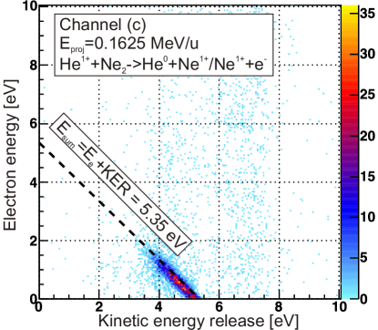
The dominant diagonal structure at Esum = 5.35 eV, also seen in jahnke2004 , can be attributed to the events in which the electron is released via ICD (the other electron has been captured by the projectile). Apart from this diagonal line the histogram also shows additional events that are spread continuously over the displayed electron energy range and which are located at 3.5 eV < EKER < 8 eV with a minimum for EKER 5.5 eV. These events can be attributed to two additional reaction mechanisms, which were reported to occur in argon dimers matsumoto2010 ; matsumoto2011 , helium dimers titze2011 and in neon dimers kim2011 after ion impact. In the first process the dimers’ constituents are ionized by two consecutive interactions with the projectile (interaction in two steps) leading to Coulomb fragmentation. For fast projectiles these collisions take place on a subfemtosecond timescale which is much shorter than the timescale for nuclear motion. Thus this direct Coulomb explosion (CE) occurs almost at the equilibrium internuclear distance of the ground state dimer. According to the reflection approximation gislason1973 the KER for the ground state bond length of the neon dimer R0,Ne2 = 3.1 Å is given by EKER = q1q2/R0,Ne = 4.6 eV, thus CE contributes to the events located at 3.5 eV < EKER < 5.5 eV. As discussed above this is about the same region in EKER populated by ICD. This degeneracy in the EKER between CE and ICD is present for all ICD channels with short life-times where the Coulomb repulsion also takes place without significant preceding nuclear motion. For this particular ICD channel in neon the life-time was predicted to be between 85 fs santra2001 and 168 fs vaval2007 . The second process creating two charged fragments is referred to as the radiative charge transfer (RCT). Here only one site of the dimer is doubly ionized (Ar2+/Ar and Ne2+/Ne) in an initial interaction with the projectile (interaction in one step). This doubly charged dimer with the charges both on one site then contracts and when the shells of both atoms start to overlap charge transfer between the two sites becomes possible. The excess energy is emitted by a photon. The subsequently formed ion pair (Ar1+/Ar1+ and Ne1+/Ne1+) then also Coulomb explodes. Due to the preceding contraction of the dimer these events are located at higher kinetic energy releases (In Fig. 1 for neon dimers at 5.5 eV < EKER < 8 eV).
If one integrates over all EKER one obtains electron energy distributions as shown in Fig. 2a - n (A detailed description is given in section ”reaction channels”.). These electron spectra show the contribution of ICD to the total production of electrons in the collision. The narrow peak at low energies in Fig. 2c corresponds to the diagonal line in Fig. 1 and hence is created by ICD while the other channels produce a broad exponentially decaying energy spectrum well-known for ion and electron impact ionization. To estimate more quantitatively the fraction of ICD electrons we have fitted the two spectral features and find a ratio of ICD electrons to all other electrons of Ne,ICD to Ne,cont. All collision systems which we studied show electron energy distributions with similar shapes (as depicted in Fig. 2) which can be qualitatively decomposed into two parts.
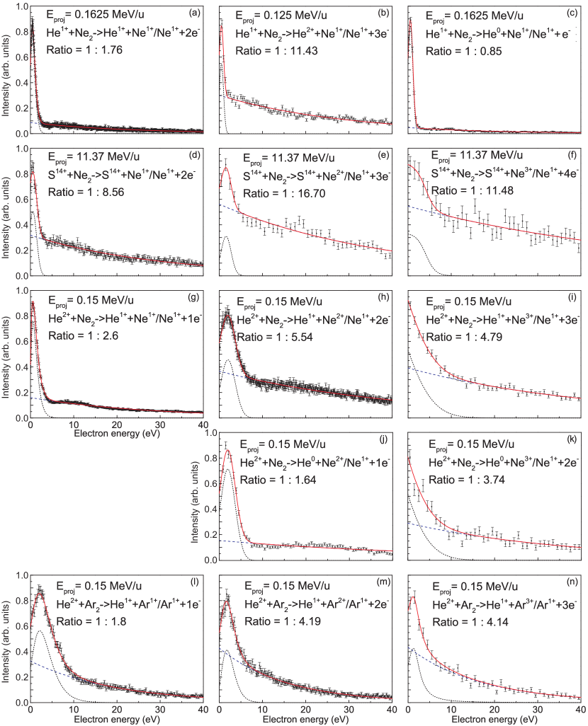
The first part are the electrons which are created in an initial interaction with the projectile and which are spread continuously over the whole electron energy range. Other than in photoionization experiments with a discrete photoelectron energy this behaviour is typical for ion induced ionization due to the continuous momentum and energy transfer. The second part is an additional peak structure at low energies on top of the continuous distribution which results from the secondary ICD electrons. A rough estimation of the fraction for the ICD electrons (eICD) to the continuous electrons (econt) is given by the ratio Ne,ICD/Ne,cont. Ne,cont and Ne,ICD were extracted by integrating the areas of two functions fitted to the peak (black short-dashed line) and to the exponentially decaying continuous distribution (blue long-dashed line) for the displayed electron energy range.
Reaction channels
An overview of the reaction channels studied is given in table 2. Here the projectile energy, initial and final projectile charge state, the final charge state of the recoil ion pair, the ratio of electrons originating from ICD to other electrons, and the experimental configuration is given. In channels a) - c) He1+ projectiles at energies from 0.125 MeV/u - 0.1625 MeV/u were utilized to induce Ne1+/Ne1+ breakups by different mechanisms of electron removal. These include at least one ionization, single capture and projectile loss processes. In d) - f) S14+ projectiles at an energy of 11.37 MeV/u were used to ionize the neon dimer leading to Ne1+/Ne1+, Ne2+/Ne1+ and Ne3+/Ne1+ ion pairs. The same final ion charge states were measured for neon dimer fragmentation with single (g) - i)) and double electron capture (j) - k)) events into (0.15 MeV/u) He2+ projectiles 333The Ne1+/Ne1+ channel for double capture is not discussed, since no ICD electron can be emitted.. Finally in l) - n) analogous processes to g) - i) were observed in argon dimers.
| Channel | Energy | Projectilei | Projectilef | Recoil ion pair | Ratio | Configuration |
|---|---|---|---|---|---|---|
| [MeV/u] | ||||||
| a)444same data as in kim2011 | 0.1625 | He1+ | He1+ | Ne1+/Ne1+ | 0.57 | II) |
| b) | 0.125 | He1+ | He2+ | Ne1+/Ne1+ | 0.09 | I) |
| c) | 0.1625 | He1+ | He0 | Ne1+/Ne1+ | 1.18 | II) |
| d) | 11.37 | S14+ | S14+ | Ne1+/Ne1+ | 0.12 | V) |
| e) | 11.37 | S14+ | S14+ | Ne2+/Ne1+ | 0.06 | V) |
| f) | 11.37 | S14+ | S14+ | Ne3+/Ne1+ | 0.09 | V) |
| g) | 0.15 | He2+ | He1+ | Ne1+/Ne1+ | 0.38 | III) |
| h) | 0.15 | He2+ | He1+ | Ne2+/Ne1+ | 0.18 | III) |
| i) | 0.15 | He2+ | He1+ | Ne3+/Ne1+ | 0.21 | III) |
| j) | 0.15 | He2+ | He0 | Ne2+/Ne1+ | 0.61 | III) |
| k) | 0.15 | He2+ | He0 | Ne3+/Ne1+ | 0.27 | III) |
| l) | 0.15 | He2+ | He1+ | Ar1+/Ar1+ | 0.56 | IV) |
| m) | 0.15 | He2+ | He1+ | Ar2+/Ar1+ | 0.24 | IV) |
| n) | 0.15 | He2+ | He1+ | Ar3+/Ar1+ | 0.24 | IV) |
Assignment of ICD in the neon dimer
The neon dimer is considered a model system for ICD. Numerous theoretical and experimental works santra2003 ; jahnke2004 ; scheit2004 ; santra2005 ; aoto2006 ; jahnke2007b ; stoychev2008 ; demekhin2008 ; kreidi2008a ; yamazaki2008 ; kreidi2008b ; kreidi2009 have been performed. Experimentally ICD like mechanisms which lead to the fragmentation channels Ne1+/Ne1+ and Ne2+/Ne1+ have been identified after irradiation by synchrotron light. These are also found in nearly all collision systems studied here. In addition we find fragmentation into Ne3+/Ne1+, which was up to now not mentioned in the literature.
Ne1+/Ne1+
The above described ”model ICD mechanism” is the main contributor to the low energy electrons seen in Fig. 2a - 2d and Fig. 2g with the neon dimer fragmenting into Ne1+/Ne1+. It can thus be seen that ICD prominently appears in all relevant channels in ion/dimer collisions. These include pure ionization (a), projectile electron loss (b) and electron transfer (c), the latter is triggered by a He1+ projectile. Qualitatively this behavior is unchanged for the single electron transfer process to the doubly charged projectile He2+ given by (g). The only collision system studied in this work which does not exhibit ICD is the double electron transfer to the He2+ projectiles with Ne1+/Ne1+ breakup for reasons of charge conservation. We note that the additional low energy electron contribution for fast (v = 21.2 a.u.), highly charged S14+ projectiles (d) is clearly visible but substantially reduced compared to (a).
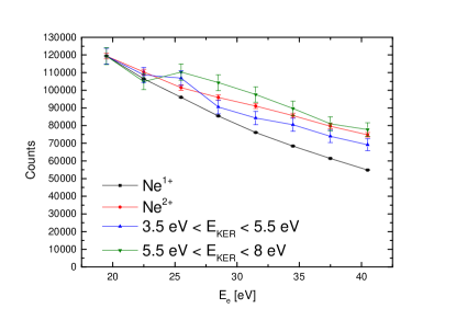
Fig. 3 shows for channel (d) the projection of the electron energies for the two regions in the kinetic energy release 3.5 eV < EKER < 5.5 eV (blue up-pointing triangles) and 5.5 eV < EKER < 8 eV (green down-pointing triangles). For comparison the electron energy distributions for singly ionized neon atoms (black squares) and doubly ionized neon atoms (red circles) are depicted. All curves are scaled to the leftmost data point of the singly ionized monomers. It can be seen that the electron energy distribution for 5.5 eV < EKER < 8 eV, where the RCT process is initiated by the double ionization of one atomic center of the dimer, shows a similar decay behavior as the electron energy distribution of the doubly ionized monomers. The electron energy distribution for the range in the kinetic energy release 3.5 eV < EKER < 5.5 eV which is populated by single ionization processes followed by CE and ICD exhibits a significantly less steeper decay than the electrons that stem from the singly ionized monomers. This discrepancy might be caused by the dominant contribution of 2s-electrons which are emitted in the ICD process.
Ne2+/Ne1+
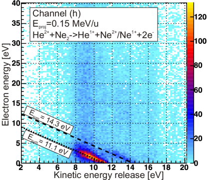
The low energy electrons in the breakup channels given by Ne2+/Ne1+ ion pairs are attributed predominantly to two ICD mechanisms which were suggested by Santra et al. santra2003 ; santra2005 and Demekhin et al. demekhin2008 and observed by Kreidi et al. kreidi2008a ; kreidi2008b in relaxation processes from the Auger decay final state Ne2+(2s-12p-1)[1P]/Ne[1S] following 1s photoionization. In the first scenario, a 2p-electron from the doubly charged ion fills the 2s-hole where the excitation energy is transferred to the neighbor by a virtual photon. There a 2p-electron is removed leading to the dimer state Ne2+(2p-2)[1D]/Ne1+(2p-)[2P]. This process termed ”direct ICD” exhibits a sum energy of Esum = EKER + Ee = 11.1 eV and occurs at distances around the equilibrium bond length of the neutral neon dimer. In the second scenario, an electron of the neutral atom fills the 2s-hole of the doubly charged ion where simultaneously a second 2p-electron of the same site is ionized by the released excess energy. This ”electron exchange” ICD, which ends in the final state Ne2+(2p-2)[1P]/Ne1+(2p-)[2P], has been reported to depend strongly on the spatial overlap of the wavefunctions jahnke2007b . This is why it is opened only for small internuclear distances, hence leading to greater kinetic energy releases. For this relaxation pathway the sum energy is Esum = 14.3 eV. In Fig. 4 (here shown for channel (h) but also visible in (e) and (j)) the sum energies of 11.1 eV for the direct ICD and 14.3 eV for the electron exchange ICD are indicated by a black dotted line and a black dashed line, respectively. Low energy electrons distributed along these lines clearly show IC decay mechanisms leading to Ne2+/Ne1+ after ion impact.
Ne3+/Ne1+
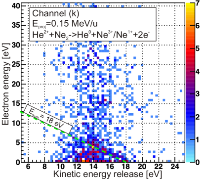
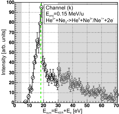
So far no theoretical prediction or experimental evidence was found in the literature which document ICD leading to the final ionic state Ne3+/Ne1+. In Fig. 5 the EKER versus electron energy histogram is shown for channel (k). Apart from CE events centered around EKER 13 eV an accummulation of events along the sum energy Esum 18 eV, indicated by the green dashed line, also suggest some type of ICD. In a one-dimensional representation of the sum energy in Fig. 6 a peak between 16 eV and 19 eV can be clearly seen.
Assignment of ICD in the argon dimer
ICD was shown to occur also in argon dimers as shown in synchrotron radiation studies hergenhahn2011 . Depending on the initial state of excitation the final charge state of the fragmenting ion pair varies, whereby breakup channels into Ar1+/Ar1+ lablanquie2007 ; kimura2013 , Ar2+/Ar1+ morishita2006 ; ueda2007 and also Ar3+/Ar1+ sakai2011 were observed. In ion collision studies between slow, highly charged Ar9+ projectiles and argon dimers matsumoto2010 ; matsumoto2011 also the breakup channels Ar1+/Ar1+, Ar2+/Ar1+, Ar3+/Ar1+ and Ar2+/Ar2+ were seen. In these studies ICD was suggested not to play a role due to electron capture mechanisms from the valence shell prohibiting the emission of an ICD electron. In our studies in fast collisions however we find reaction channels where at least one electron is emitted, thus opening ICD as a fast relaxation mechanism. The experimental resolution in the sum energy does however not suffice to observe any discrete diagonal structures for the argon dimers.
Ar1+/Ar1+
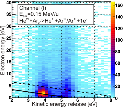
ICD in argon dimers with fragmentation into Ar1+/Ar1+ was reported by Lablanquie et al. lablanquie2007 by measuring the intensity of high energetic (from Coulomb explosion) Ar+ ions after photon irradiation (Eγ = 25 - 40 eV). Several satellite states of the singly ionized argon dimer Ar+∗-Ar were assumed to relax via ICD. Kimura et al. kimura2013 showed by a coincident ion-ion-electron measurement that a variety of states are also created by resonant Auger decay in argon dimers which then decay via ICD fragmenting to Ar+(3p-1)-Ar+(3p-1). The main contributions were assigned to the channels Ar+[3p-2(1D) 3d 2D]-Ar Ar+(3p-1)-Ar+(3p-1) (Esum = 5.4 eV) and Ar+[3p-2(1D) 4d 2D]-Ar Ar+(3p-1)-Ar+(3p-1) (Esum = 8.6 eV) indicated by the solid and dashed lines in Fig. 7, respectively. Although intense ”islands” can be clearly distinguished along these two lines the broadness of the structures indicates that many more satellite states of the dimer are populated which cannot be resolved.
Ar2+/Ar1+
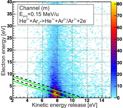
ICD with breakups into Ar2+/Ar1+ ions are reported to originate mainly from Ar2+(3p3)-Ar states which then decay into Ar2+(3p-2)-Ar1+(3p-1) states morishita2006 ; ueda2007 . In particular the events from the relaxation paths denoted by Ar2+(3p-33d)[1P]-Ar Ar2+(3p-2)[3P]-Ar1+(3p-1)[2P] (Esum = 11.5 eV) and Ar2+(3p-33d)[1P]-Ar Ar2+(3p-2)[]-Ar1+(3p-1)[2P] (Esum = 9.8 eV) seem to significantly produce the low energy electrons. Their sum energies are marked in Fig. 8 by black dashed lines. Also the events from Ar2+(3p-33d)[3P]-Ar leading to the same final states are energetically located only 0.73 eV below the other channels in the sum energy (green solid lines in Fig. 8). Additional weak contributions from among others Ar2+(3s-2)[1S]-Ar and Ar2+(3p-32D 4d3P)-Ar fragmenting to the states Ar2+(3p-2)[3P]-Ar1+(3p-1)[2P], Ar2+(3p-2)[]-Ar1+(3p-1)[2P] and Ar2+(3p-2)[]-Ar1+(3p-1)[2P] via ICD are assumed to add to the yield of electrons up to energies around 10 eV ueda2007 . In Fig. 8 the data is located between 6 eV < EKER < 10 eV. Apart from the decay via direct Coulomb explosion (CE expected to occur around 7.6 eV) we attribute the accumulation of electrons at energies below roughly 10 eV to ICD.
Ar3+/Ar1+
In 2011 Sakai et al. sakai2011 showed that ICD occurs from triply charged states of the argon dimer Ar3+-Ar resulting in Ar3+-Ar1+ states. They observed peaks of 11 eV in the EKER (corresponding to the bond length of the ground state argon dimer r0,Ar2 = 3.76 Å stoychev2008b ; patkowski2005 within the reflection approximation) and at about 1 eV in the electron energy which were attributed to exchange ICD from Ar3+(3s3p4)[2P]-Ar to Ar3+(3p3)[4S]-Ar1+(3p5)[2P]. Also direct ICD from various satellite states were reported to be energetically allowed. Similar to the Ar2+/Ar1+ case the peak in Fig. 2n is attributed to ICD events.
IV Conclusions
In conclusion we report of an increased low energy electron yield in a broad range of ion/Ne2 and ion/Ar2 collisions. The projectiles differ in charge state and velocity as well as the change of the charge state after the reaction which arises from pure ionization, projectile electron loss, single and double electron capture. This surplus of electrons can be unambiguously assigned to ICD in the case of Ne1+/Ne1+ and Ne2+/Ne1+. For all other channels ICD was also shown to be responsible for the enhanced emission of low energy electrons. Except for the Ne1+/Ne1+ fragmentation after ionization kim2011 ICD was observed for the first time in all remaining ion/dimer collisions. Our comprehensive study suggests that in fast ion collisions with loosely bound matter ICD is omnipresent. It is a major contributor to the creation of low energy electrons.
Acknowledgements.
This work has been supported by DFG and by the European Community FP7 - Capacities- Integrated Infrastructure Initiative- contract ENSAR n∘ 262010. We gratefully acknowledge the GANIL and CIMAP staff for their exceptional help during the experiment in Caen and K. Stiebing, P. Ziel, W. Dilfer, and M. Dworak for the excellent preparation of the ion beam in Frankfurt.References
- (1) M. E. Rudd, L. H. Toburen and N. Stolterfoht, , At. Data Nucl. Data Tables 18, 413 (1976).
- (2) M. E. Rudd, L. H. Toburen and N. Stolterfoht, , At. Data Nucl. Data Tables 23, 405 (1979).
- (3) H.-K. Kim, J. Titze, M. Schöffler, F. Trinter, M. Waitz, J. Voigtsberger, H. Sann, M. Meckel, C. Stuck, U. Lenz, M. Odenweller, N. Neumann, S. Schössler, K. Ullmann-Pfleger, B. Ulrich, R. Costa Fraga, N. Petridis, D. Metz, A. Jung, R. Grisenti, A. Czasch, O. Jagutzki, L. Schmidt, T. Jahnke, H. Schmidt-Böcking and R. Dörner, Proc. Natl. Acad. Sci. U.S.A., 108, 11821, (2011).
- (4) B. Boudaïffa, P. Cloutier, D. Hunting, M. A. Huels and L. Sanche, Science 287,1658–1660, (2000).
- (5) G. Hanel, B. Gstir, S. Denifl, P. Scheier, M. Probst, B. Farizon, M. Farizon, E. Illenberger, and T. D. Märk, Phys. Rev. Lett 90, 188104-1, (2003).
- (6) L. Sanche, Eur. Phys. J. D 35, 367-390, (2005).
- (7) F. Martin, P. D. Burrow, Z. Cai, P. Cloutier, D. Hunting, and L. Sanche, Phys. Rev. Lett 93, 068101-1, (2004).
- (8) K. Gokhberg, P. Kolorenc, A. I. Kuleff, and L. S. Cederbaum, (unpublished).
- (9) L. S. Cederbaum, J. Zobeley, and F. Tarantelli, Phys. Rev. Lett 79, 4778, (1997).
- (10) S. Marburger, O. Kugeler, U. Hergenhahn, T. Möller, Phys. Rev. Lett 90, 203401-1, (2003).
- (11) T. Jahnke, A. Czasch, M. S. Schöffler, S. Schössler, A. Knapp, M. Käsz, J. Titze, C. Wimmer, K. Kreidi, R. E. Grisenti, A. Staudte, O. Jagutzki, U. Hergenhahn, H. Schmidt-Böcking, and R. Dörner, Phys. Rev. Lett 93, 163401-1, (2004).
- (12) T. Ouchi, K. Sakai, H. Fukuzawa, X.-J. Liu, I. Higuchi, Y. Tamenori, K. Nagaya, H. Iwayama, M. Yao, D. Zhang, D. Ding, A. I. Kuleff, S. D. Stoychev, Ph. V. Demekhin, N. Saito, and K. Ueda, Phys. Rev. Lett 107, 053401-1, (2011).
- (13) T. Havermeier, T. Jahnke, K. Kreidi, R. Wallauer, S. Voss, M. Schöffler, S. Schössler, L. Foucar, N. Neumann, J. Titze, H. Sann, M. Kühnel, J. Voigtsberger, J. H. Morilla, W. Schöllkopf, H. Schmidt-Böcking, R. E. Grisenti, and R. Dörner, Phys. Rev. Lett 104, 133401, (2010).
- (14) N. Sisourat , N. V. Kryzhevoi, P. Kolorenc, S. Scheit, T. Jahnke, and L. S. Cederbaum, Nature Physics 6, 508, (2010).
- (15) T. Jahnke, H. Sann, T. Havermeier, K. Kreidi, C. Stuck, M. Meckel, M. Schöffler, N. Neumann, R. Wallauer, S. Voss, A. Czasch, O. Jagutzki, A. Malakzadeh, F. Afaneh, Th. Weber, H. Schmidt-Böcking, and R. Dörner, Nature Physics 6, 139, (2010).
- (16) M. Mucke, M. Braune, S. Barth, M. Förstel, T. Lischke, V. Ulrich, T. Arion, U. Becker, A. Bradshaw, and Uwe Hergenhahn, Nature Physics 6, 143, (2010).
- (17) E. F. Aziz, N. Ottosson, M. Faubel, I. V. Hertel, and B. Winter, Nature 455, 89, (2008).
- (18) A. Bande, K. Gokhberg, and L. S. Cederbaum, J. Chem. Phys. 135, 144112, (2011).
- (19) G. A. Grieves and T. M. Orlando, Phys. Rev. Lett. 107, 016104, (2011).
- (20) T. Jahnke, A. Czasch, M. Schöffler, S. Schössler, M. Käsz, J. Titze, K. Kreidi, R. E. Grisenti, A. Staudte, O. Jagutzki, L. Ph. H. Schmidt, S. K. Semenov, N. A. Cherepkov, H. Schmidt-Böcking and R. Dörner, J. Phys. B 40, 2597, (2007).
- (21) P. Lablanquie, T. Aoto, Y. Hikosaka, Y. Morioka, F. Penent and K. Ito, J. Chem. Phys. 127, 154323, (2007).
- (22) K. Ueda, X.-J. Liu, G. Pruemper, H. Fukuzawa, Y. Morishita and N. Saito, J. Electron Spectrosc. Relat. Phenom. 155, 113, (2007).
- (23) Y Morishita, N Saito, I H Suzuki, H Fukuzawa, X-J Liu, K Sakai, G Prümper, K Ueda, H Iwayama, K Nagaya, M Yao, K Kreidi, M Schöffler, T Jahnke, S Schössler, R Dörner, T Weber, J Harries and Y Tamenori, J. Phys. B 41, 025101, (2008).
- (24) S. D. Stoychev, J. Chem. Phys. 129, 074307, (2008).
- (25) K. Ueda, H. Fukuzawa, X.-J. Liu, K. Sakai, G. Prümper, Y. Morishita, N. Saito, I.H. Suzuki, K. Nagaya, H. Iwayama, M. Yao, K. Kreidi, M. Schöffler, T. Jahnke, S. Schössler, R. Dörner, Th. Weber, J. Harries, and Y. Tamenori, J. Electron Spectrosc. Relat. Phenom. 166-167, 3, (2008).
- (26) K. Kreidi, T. Jahnke, Th. Weber, T. Havermeier, X. Liu, Y. Morisita, S. Schössler, L. Ph. H. Schmidt, M. Schöffler, M. Odenweller, N. Neumann, L. Foucar, J. Titze, B. Ulrich, F. Sturm, C. Stuck, R. Wallauer, S. Voss, I. Lauter, H. K. Kim, M. Rudloff, H. Fukuzawa, G. Prümper, N. Saito, K. Ueda, A. Czasch, O. Jagutzki, H. Schmidt-Böcking, S. Stoychev, Ph. V. Demekhin and R. Dörner, Phys. Rev. A 78, 043422-1, (2008).
- (27) K. Kreidi, T. Jahnke, Th. Weber, T. Havermeier, R. E. Grisenti, X. Liu, Y. Morisita, S. Schössler, L. Ph. H. Schmidt, M. Schöffler, M. Odenweller, N. Neumann, L. Foucar, J. Titze, B. Ulrich, F. Sturm, C. Stuck, R. Wallauer, S. Voss, I. Lauter, H. K. Kim, M. Rudloff, H. Fukuzawa, G. Prümper, N. Saito, K. Ueda, A. Czasch, O. Jagutzki, H. Schmidt-Böcking, S. K. Semenov, N. A. Cherepkov, and R. Dörner, J. Phys. B, 41, 101002, (2008).
- (28) A. M. Dias, Physica B, 403, 3490, (2008).
- (29) Ph. V. Demekhin, S. Scheit, S. D. Stoychev, L. S. Cederbaum, Phys. Rev. A, 78, 043421, (2008).
- (30) K. Kreidi, Ph.V. Demekhin, T. Jahnke, Th. Weber, T. Havermeier, X.-J. Liu, Y. Morisita, S. Schössler, L. Ph. H. Schmidt, M. Schöffler, M. Odenweller, N. Neumann, L. Foucar, J. Titze, B. Ulrich, F. Sturm, C. Stuck, R. Wallauer, S. Voss, I. Lauter, H. K. Kim, M. Rudloff, H. Fukuzawa, G. Prümper, N. Saito, K. Ueda, A. Czasch, O. Jagutzki, H. Schmidt-Böcking, S. Scheit, L. S. Cederbaum and R. Dörner, Phys. Rev. Lett. 103, 033001-1, (2009).
- (31) T. Arion, M. Mucke, M. Förstel, A. M. Bradshaw, and Uwe Hergenhahn, J. Chem. Phys. 134, 074306, (2011).
- (32) T. Havermeier, K. Kreidi, R. Wallauer, S. Voss, M. Schöffler, S. Schössler, L. Foucar, N. Neumann, J. Titze, H. Sann, M. Kühnel, J. Voigtsberger, N. Sisourat, W. Schöllkopf, H. Schmidt-Böcking, R. E. Grisenti, R. Dörner and T. Jahnke, Phys. Rev. A 82, 063405-1, (2010).
- (33) T. Ouchi, K. Sakai, H. Fukuzawa, I. Higuchi, Ph. V. Demekhin, Y.-C. Chiang, S. D. Stoychev, A. I. Kuleff, T. Mazza, M. Schöffler, K. Nagaya, M. Yao, Y. Tamenori, N. Saito, and K. Ueda, Phys. Rev. A 83, 053415, (2011).
- (34) K. Sakai, S. Stoychev, T. Ouchi, I. Higuchi, M. Schöffler, T. Mazza, H. Fukuzawa, K. Nagaya, M. Yao, Y. Tamenori, A. I. Kuleff, N. Saito, and K. Ueda, Phys. Rev. Lett. 106, 033401, (2011).
- (35) S. K. Semenov, K. Kreidi, T. Jahnke, Th. Weber, T. Havermeier, R. E. Grisenti, X. Liu, Y. Morisita, L. Ph. H. Schmidt, M. S. Schöffler, M. Odenweller, N. Neumann, L. Foucar, J. Titze, B. Ulrich, F. Sturm, H. K. Kim, K. Ueda, A. Czasch, O. Jagutzki, N. A. Cherepkov, and R. Dörner, Phys. Rev. A 85, 043421, (2012).
- (36) V. Averbukh, Ph.V. Demekhin, P. Kolorenc, S. Scheit, S.D. Stoychev, A.I. Kuleff, Y.-C. Chiang, K. Gokhberg, S. Kopelke, N. Sisourat, and L.S. Cederbaum, J. Electron Spectrosc. Relat. Phenom. 183, 36, (2011).
- (37) U. Hergenhahn, J. Electron Spectrosc. Relat. Phenom. 184, 78, (2011).
- (38) M. Kimura, H. Fukuzawa, K. Sakai, S. Mondal, E. Kukk, Y. Kono, S. Nagaoka, Y. Tamenori, N. Saito, and K. Ueda, Phys. Rev. A 87, 043414, (2013).
- (39) F. Trinter, M. S. Schöffler, H.-K. Kim, F. Sturm K. Cole, N. Neumann, A. Vredenborg, J. Williams, I. Bocharova, R. Guillemin, M. Simon, A. Belkacem, A. L. Landers, Th. Weber, H. Schmidt-Böcking, R. Dörner, and T. Jahnke (unpublished).
- (40) J. Titze, M. S. Schöffler, H.-K. Kim, F. Trinter, M. Waitz, J. Voigtsberger, N. Neumann, B. Ulrich, K. Kreidi, R. Wallauer, M. Odenweller, T. Havermeier, S. Schössler, M. Meckel, L. Foucar, T. Jahnke, A. Czasch, L. Ph. H. Schmidt, O. Jagutzki, R. E. Grisenti, H. Schmidt-Böcking, H. J. Lüdde, and R. Dörner, Phys. Rev. Lett. 106, 033201, (2011).
- (41) R. Garcia-Molina, I. Abril, C. D. Denton, S. Heredia-Avalos, I. Kyriakou, and D. Emfietzoglou, Nucl. Instrum. Methods Phys. Res., Sect. B 267, 2647, (2009).
- (42) R. B. J. Palmer and A. Akhavan-Rezayatt, J. Phys. D 11, 605, (1978).
- (43) A. K. M. M. Haque, A. Mohammadi, and H. Nikjoo, Radiation Protection Dosimetry 13, 71, (1985).
- (44) J. Ullrich, R. Moshammer, A. Dorn, R. Dörner, L. Ph. H.Schmidt and H. Schmidt-Böcking, Rep. Prog. Phys., 66, 1463, (2003).
- (45) R. Dörner, V. Mergel, O. Jagutzki, L. Spielberger, J. Ullrich. R. Moshammer and H. Schmidt-Böcking, Physics Reports, 330, 95, (2000).
- (46) O. Jagutzki, J. S. Lapington, L. B. C. Worth, U. Spillman, V. Mergel and H. Schmidt-Böcking, Nucl. Instr. and Meth. in Phys. Res. A, 477, 256, (2002).
- (47) O. Jagutzki, V. Mergel, K. Ullmann-Pfleger, L. Spielberger, U. Spillmann, R. Dörner and H. Schmidt-Böcking, Nucl. Instr. and Meth. in Phys. Res. A, 477, 244, (2002).
- (48) A. Wuest and F. Merkt, J. Chem. Phys., 118, 8807, (2003).
- (49) J. Matsumoto, A. Leredde, X. Flechard,K. Hayakawa, H. Shiromaru, J. Rangama, C. L. Zhou, S. Guillous, D. Hennecart, T. Muranaka, A. Mery, B. Gervais, and A. Cassimi, Phys. Rev. Lett., 105, 263202, (2010).
- (50) J Matsumoto , A Leredde , X Flechard , K Hayakawa , H Shiromaru , J Rangama , C L Zhou , S Guillous , D Hennecart , T Muranaka , A Mery , B Gervais, and A Cassimi, Physica Scripta, T144, 014016, (2011).
- (51) E.A. Gislason, J. Chem. Phys., 58, 3702, (1973).
- (52) R. Santra, and L. S. Cederbaum, J. Chem. Phys., 115, 6853, (2001).
- (53) N. Vaval, and L. S. Cederbaum, J. Chem. Phys., 126, 164110, (2007).
- (54) R. Santra, and L.S. Cederbaum, Phys. Rev. Lett., 90, 153401, (2003).
- (55) S. Scheit, V. Averbukh,H.-D. Meyer, N. Moiseyev, R. Santra, T. Sommerfeld, J. Zobeley and L. S. Cederbaum, J. Chem. Phys. 121, 8393, (2004).
- (56) R. Santra, and L.S. Cederbaum, Phys. Rev. Lett., 94, 199901(E), (2005).
- (57) T. Aoto, K. Ito, Y. Hikosaka, E. Shigemasa, F. Penent and P. Lablanquie, Phys. Rev. Lett. 97, 243401, (2006).
- (58) M.Yamazaki, J. I. Adachi, Y. Kimura, A. Yagishita, M. Stener, P. Decleva, N. Kosugi, H. Iwayama, K. Nagaya, and M. Yao, Phys. Rev. Lett., 101, 043004, (2008).
- (59) T. Jahnke, A. Czasch, M. Schöffler, S. Schössler, M. Käsz, J. Titze, K. Kreidi, R. E. Grisenti, A. Staudte, O. Jagutzki, L. Ph. H. Schmidt, Th. Weber, H. Schmidt-Böcking, K. Ueda, and R. Dörner, Phys. Rev. Lett., 99, 153401, (2007).
- (60) Y. Morishita,X.-J. Liu, N. Saito, T. Lischke, M. Kato, G. Prümper, M. Oura, H. Yamaoka, Y. Tamenori, I. H. Suzuki and K. Ueda, Phys. Rev. Lett., 96, 243402, (2006).
- (61) S. D. Stoychev, A. I. Kuleff, F. Tarantelli, and L. S. Cederbaum, J. Chem. Phys. 128, 014307 (2008).
- (62) K. Patkowski, G. Murdachaew, C.-M. Fou, and K. Szalewicz, Mol. Phys. 103, 2031 (2005), and references therein.