Nonlinear Surface-Plasmon Whispering-Gallery Modes in Metallic Nanowire Cavities
Abstract
We demonstrate that the surface second-harmonic generation can lead to the formation of nonlinear plasmonic whispering-gallery modes (WGMs) in microcavities made of metallic nanowires. Since these WGMs are excited by induced surface nonlinear dipoles, they can be generated even when they are not coupled to the radiation continuum. Consequently, the quality factor of these nonlinear modes can be as large as the theoretical limit imposed by the optical losses in the metal. Remarkably, our theoretical analysis shows that nonlinear plasmonic WGMs are characterized by fractional azimuthal modal numbers. This suggests that the plasmonic cavities investigated here can be used to generate multi-color optical fields with fractional angular momentum. Applications to plasmonic sensors are also discussed.
pacs:
42.79.Gn, 42.65.Ky, 73.20.Mf, 42.79.-eWhispering-gallery (WG) optical microresonators play a key role in many photonic applications, including microcavity lasers mls92apl ; ctn11np , optical filters and modulators dcd02ptl ; rsz02jlt ; km07ol , lasers kdh92ol ; sth96pra ; pmk04apl , mechanical, chemical, and biological sensors msi04oc ; ssr04pccp ; vbl02apl , nonlinear optics bgi89pla ; ksv04prl , and quantum optics cel91prl ; vfg98pra ; aww01nl (for a review of the properties of WG microresonators and their applications see Refs. mi06stq ; ia06stq ). These microresonators are essential elements in such a broad array of applications due to the unique properties of their optical modes, namely the strong confinement and enhancement of the optical field, and the rich spectrum of available choices for optical materials and configurations that can be used to fabricate WG microresonators. In particular, closely spaced WG modes (WGMs) with ultra-high -factor and small modal volume can be easily achieved, , by using dielectric microspheres, capillary cavities, photonic crystal cavities, and liquid droplets. However, since WGMs are formed by total internal reflection at closed, curved interfaces, reducing the modal volume of WGMs of dielectric based microresonators beyond a few cubic wavelengths is a major challenge.
The size of WGMs can be significantly decreased by using plasmonic resonators, such as metallic nanoparticles and cavities csb06prl ; mos09nat ; nzb09nat ; nsb10natp ; vgp09nl ; xzl10prl , as they can confine the optical field to a domain that is comparable or significantly smaller than the optical wavelength bde03n ; zsm05pr ; vme10rmp ; m07book . While -factors of plasmonic resonators are smaller than those of dielectric cavities, chiefly due to the optical losses in the metal, plasmonic cavities with -factors larger than have been recently demonstrated mos09nat ; nsb10natp ; bp1011oenan . As a result, it is possible to achieve plasmonic resonators with ratio between the -factor and the modal volume, which is a key figure of merit of the performance of optical cavities, as large as that of dielectric cavities. However, unlike dielectric cavities, plasmonic resonators can enhance the optical near-field at the metal surface by more than two orders of magnitude, which, in conjunction with the strong sensitivity of the near-field to changes of the physical and chemical properties of metal surfaces, can be exploited in many applications pertaining to light control at deep subwavelength scale. This is particularly important in the case of nonlinear optics applications, as then the local field enhancement effect is greatly amplified by the nonlinear character of the optical interaction.
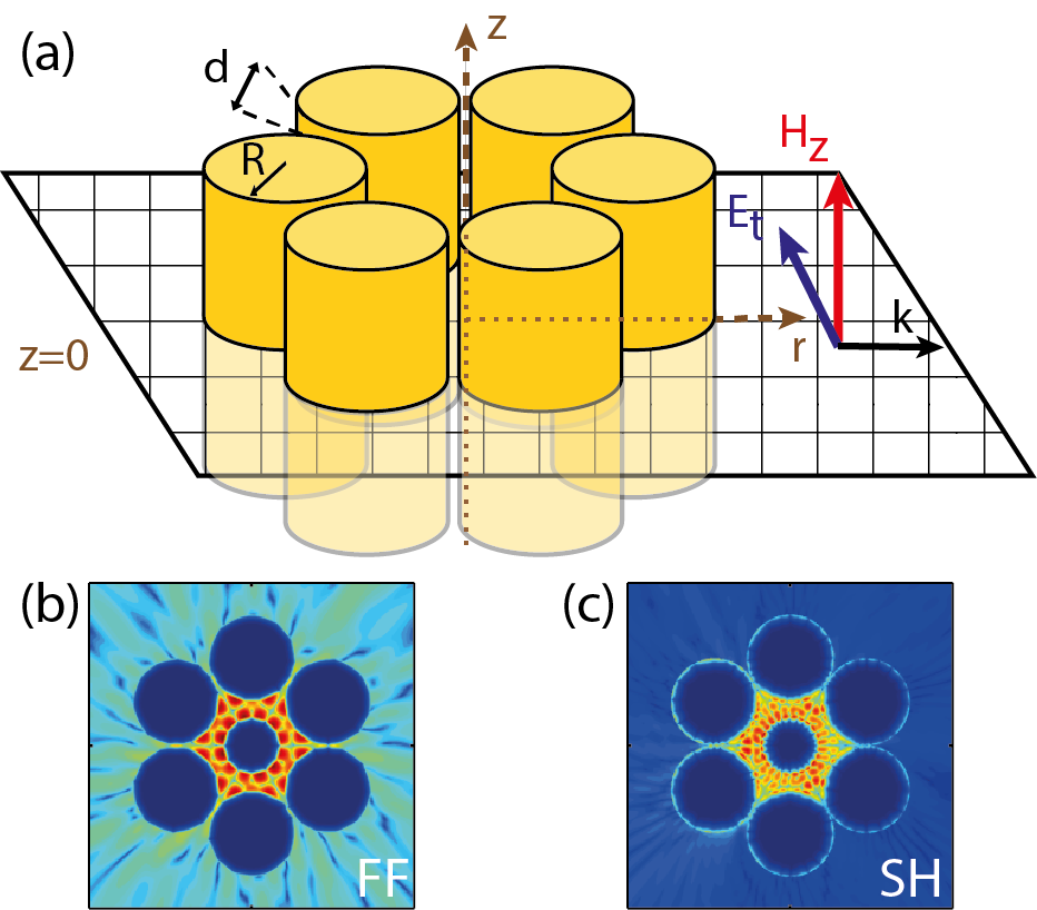
In this Letter we reveal for the first time the existence of nonlinear plasmonic WGMs formed as the result of second-harmonic generation (SHG) in plasmonic cavities made of metallic nanowires. Importantly, these nonlinear WGMs do not couple with the free-space radiative modes, which allows one to achieve -factors as large as the theoretical limit imposed by the optical loss in the metal. A typical geometry of the cavities considered in our study is shown in Fig. 1. The cavity consists of infinite, parallel nanowires made of Au, which are embedded in a dielectric medium with permittivity . The nanowires have radius and are separated by a distance, . In a more general case, we assume that at the center of the cavity there is another nanowire with radius .
Theoretical analysis and numerical method.—To study the nonlinear WGMs of plasmonic cavities we use a well known numerical algorithm based on the multiple-scattering matrix (MSM) method ftm94josaa , modified to account for the surface SHG bp10prb . To begin with, we assume that the plasmonic cavity is excited by a TE polarized field. For the TM polarization the electric field is parallel to the surface of the nanowires and thus no SH is generated. Thus, we write the excitation field (a plane-wave in our case), , at the FF, , as a Fourier-Bessel series,
| (1) |
where are the expansion coefficients of the excitation field. For simplicity, we have used Dirac notation, with the excitation field in the real space being , the z-component of the magnetic field of the incident wave. In this notation, are multipole functions of m-th order (), with being cylindrical Bessel functions of first kind. For a plane wave excitation, , the coefficients , so that the symmetry relation holds. The total field can be written as the sum between the excitation and scattered fields, . The scattered field is expanded as
| (2) |
Here, are the expansion coefficients of the scattered field and are multipole functions of m-th order given in a coordinate system with origin at the center of cylinder . Due to the boundary conditions at infinity, the scattered field is expressed in terms of outgoing cylindrical Hankel functions of second kind, . In the MSM formalism the coefficients (and implicitly the total field at the FF) can be calculated by solving a system of linear equations, (the vectors and depend only on the coefficients and , respectively), with the scattering matrix, , being fully determined by the distribution and material parameters of the nanowires ftm94josaa .
In the second step of the nonlinear MSM method one determines the field at the SH, generated by the nonlinear polarization, , where . Here, the first term is a local dipole surface polarization and the last three terms describe the nonlocal, bulk polarization h91book . If the free electrons in the metal are described by the Drude model then , , and , where and are the electron charge and mass, respectively, and is the Drude permittivity. For Au plasma frequency, , and damping frequency, oba85ao . The surface susceptibility of homogeneous, isotropic centrosymmetric media, such as noble metals, has three independent components, which for Au are , , and ktr04jap .
The total field at the SH, , is the sum between the scattered field, , and the source field, , generated by the nonlinear polarization . The source field obeys the inhomogeneous Helmholtz equation and thus it can be calculated as the convolution between the Green function of the 2D Helmholtz equation, , and the corresponding source term: . Similarly to Eq. (2), the scattered field can be expanded as
| (3) |
where the coefficients can be determined by solving a linear system of equations, . Here, the vector is known, being determined by the expansion coefficients of the source field, and is the nonlinear scattering matrix of the system (a detailed description of this method can be found in Ref. bp10prb ).
Properties of nonlinear plasmonic WGMs.—We have used this approach to explore the physical properties of nonlinear plasmonic WGMs and how they are influenced by the cavity geometry and the electromagnetic properties of the surrounding medium. To begin with, we show in Figs. 1(b) and 1(c) a generic example of a nonlinear WGM of a hexagonal plasmonic cavity. This mode has been computed by using a multipole source , namely, all coefficients in Eq. (1) were set to zero, except the one with . Note that the field profiles of the WGM in Fig. 1 are the scattered fields at the FF and SH, which do not depend on the particular way in which the mode is excited. However, by properly setting the value of one can excite WGMs with specific symmetry, i.e. modes that are invariant to symmetry operations of the symmetry group of -fold rotations.
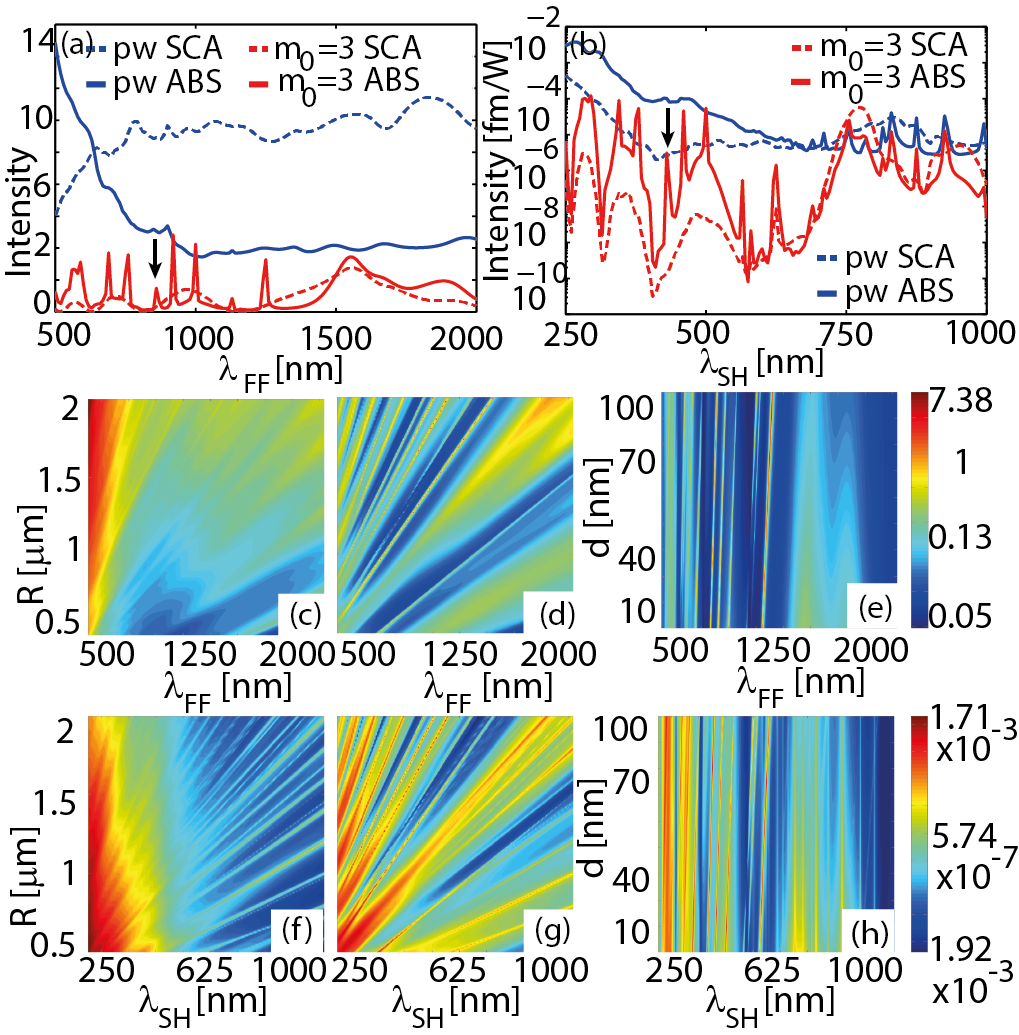
The most efficient way to find WGMs of the cavity is to determine the resonances in the absorption and scattering cross-section spectra, at both the FF and SH. Figures 2(a) and 2(b) show the cross-section spectra corresponding to a hexagonal cavity that is excited by either a plane wave or a multipole source with . As the strong field confinement leads to increased optical absorption in the metal, absorption spectra reveal more information about the modes of the cavity as compared to the scattering spectra. Indeed, it can be seen in Figs. 2(a) and 2(b) that the absorption spectra contain a larger number of spectral peaks. Another important idea revealed by these spectra is that multipole sources excite many more modes than plane waves. Because plane waves cannot excite WGMs (they do not carry angular momentum) we expect that the additional resonances seen in the spectra corresponding to multipole source excitation are associated to WGMs. Equally important is the fact that in most cases a spectral resonance at the FF has a counterpart in the SH spectra, which means that they correspond to two-component (multi-color) nonlinear modes. This is primarily because a strong field at the FF generates a large nonlinear polarization and consequently an enhanced field and optical absorption at the SH.
Further insights into the nature of the cavity modes are provided by the dispersion maps of the absorption spectra shown in Figs. 2(c)-2(h). Thus, is can be seen that while the resonance wavelength of all cavity modes varies with the radius of the nanowires, it depends on the separation distance only for certain modes. The modes which are independent on represent multipole plasmon modes of single nanowires whereas the modes whose resonance wavelength varies with are plasmonic cavity modes. Of these latter ones, plasmonic WGMs are those that do not couple with plane waves, i.e., they are only excited by multipole sources. This shows that one can find WGMs with specific symmetry properties by simply setting the order of the multipole source, .
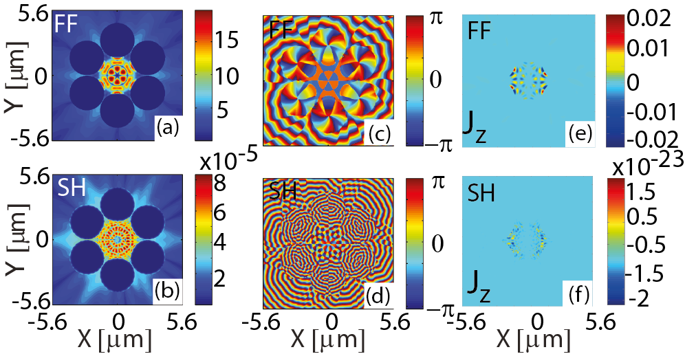
The symmetry properties of the nonlinear WGMs are illustrated by the spatial distribution of the optical field and its phase, as shown in Figs. 3(a)-3(d). Thus, it can be seen that the field at the SH has twice as many nodes on circles centered at the origin as compared to the field at the FF, a property that is not specific to this particular nonlinear WGM. In particular, the phase of the magnetic field indicates the existence of an optical vortex located at the center of the cavity, its topological charge being at the FF and at the SH.
In order to quantify the angular momentum carried by the WGMs we introduce an effective azimuthal modal number, , where and are the optical cycle-averaged -component of the total angular momentum and electromagnetic energy, per unit length, respectively. For the TE polarization they are given by:
| (4a) | |||||
| (4b) | |||||
Our choice for the definition of is guided by the fact that for a multipole field with axial index n08book . Note, however, that for such a field both and are infinite. From a physical point of view, represents the average angular momentum carried by a photon in the mode, in units of . Figures 3(e) and 3(f) show that the total at both the FF and SH, the calculated effective azimuthal modal numbers being (FF) and (SH), i.e. within numerical errors. These results show that, remarkably, plasmonic systems can have multi-color nonlinear plasmonic modes caring fractional angular momentum at both frequencies, meaning that such peculiar modes are not restricted to the linear regime rfm12prb .
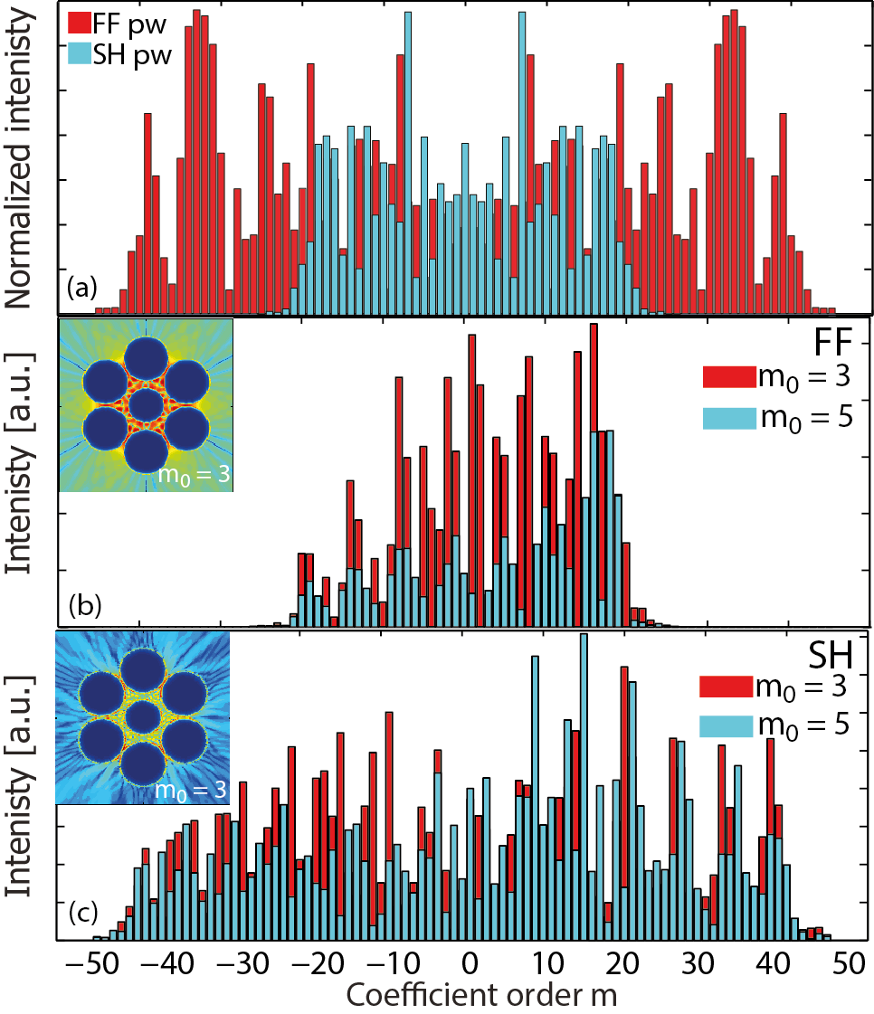
More physical insights into the properties of the WGMs, i.e. the origin of the fractional character of their angular momentum, can be inferred by analyzing the angular dependence of the optical field, which is determined by the spectrum of the Bessel-Fourier coefficients of the field scattered at the FF and SH. Thus, one can easily demonstrate that in the case of an incident plane wave with the wave vector along one of the symmetry axes of the cavity the scattering coefficients expressed in the coordinate system with the origin at the center of the cavity satisfy the symmetry relations and [see Fig. 4(a)]. Hence, the cylindrical multipoles with axial number and contribute equally to the scattered field, at both the FF and SH. Therefore, in this case , meaning that no WGMs can be excited. These symmetry relations no longer hold for a multipole source excitation (), implying that in this case plasmonic modes with finite angular momentum can exist. This modal asymmetry is illustrated by the spectra of the Bessel-Fourier coefficients shown in Figs. 4(b) and 4(c), which correspond to and , respectively. These spectra also show that, as expected, a cavity with -fold symmetry will predominantly scatter the field produced by a multipole source with axial number into modes with , with . In addition, when the amplitudes of the scattering coefficients are larger than in the case of , which is explained by the fact that in the former case there is a stronger overlap among the modes with the predominant contribution to the scattering process ( vs. , respectively).
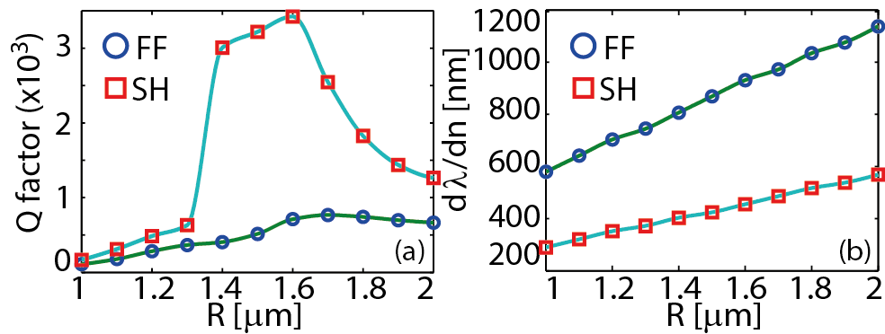
Applications of nonlinear WGMs to plasmonic sensors.—Plasmonic cavities have optical modes with extremely small modal volume and relatively large -factor, which makes them suitable for ultra-compact sensing devices ia06stq ; bp1011oenan . To assess the potential of nonlinear WGMs for sensing applications we calculated -factor and sensitivity, , being the background refractive index, of the WGM presented in Fig. 3. The results of this analysis are shown in Fig. 5.
Because WGMs do not couple to the radiation continuum, one expects that they have large , a conclusion validated by the results shown in Fig. 5(a). In fact, our calculations suggest that nonlinear WGMs have larger as compared to that of plasmonic cavity modes with bp1011oenan . Another unique feature of WGMs is that, unlike modes with , they can be used to probe at the nanoscale optical near-fields with specific chirality. While -factor is relatively large at both the FF and SH, it is larger at the SH, reaching a particularly large maximum value of for . Equally important, Fig. 5(b) shows that the sensitivity of the WGM is extremely large as well. In particular, for , which is about three times larger than recently reported sensitivities of sensors employing localized plasmon modes lmw10nl . Not surprisingly, the sensitivity at the FF is about twice as large as that at the SH, which is the same as the ratio of the two wavelengths.
To conclude, we have demonstrated that plasmonic microcavities made of metallic nanowires have nonlinear WGMs with particularly large -factors and sensitivities. These unique properties, of significant practical relevance, are a consequence of the fact that nonlinear WGMs do not couple to the radiation continuum. Importantly, nonlinear plasmonic WGMs can have fractional azimuthal modal index, which opens up the possibility to generate at the nanoscale optical fields with fractional angular momentum. Applications of WGMs to nano-optics, including plasmonic sensors, have also been discussed.
Aknowledgements.—The authors acknowledge the use of the UCL Legion High Performance Computing Facility (Legion@UCL), and associated support services, in the completion of this work. This work was supported by the EPSRC.
References
- (1) S. L. MccCall, A. F. J. Levi, R. E. Slusher, S. J. Pearton, and R. A. Logan, Appl. Phys. Lett. 60, 289 (1992).
- (2) R. Chen, T. T. D. Tran, K. W. Ng, W. S. Ko, L. C. Chuang, F. G. Sedgwick, and C. Chang-Hasnain, Nature Photon. 5, 170 (2011).
- (3) K. Djordjev, S. J. Choi, and P. D. Dapkus, IEEE Phot. Technol. Lett. 14, 828 (2002).
- (4) P. Rabiei, W. H. Steier, C. Zhang, and L. R. Dalton, J. Lightwave Technol. 20, 1968 (2002).
- (5) K. Kieu and M. Mansuripur, Opt. Lett. 32, 244 (2007).
- (6) J. C. Knight, H. S. T. Driver, R. J. Hutcheon, and G. N. Robertson, Opt. Lett. 17, 1280 (1992).
- (7) V. Sandoghdar, F. Treussart, J. Hare, V. Lefevre-Seguin, J. M. Raimond, and S. Haroche, Phys. Rev. A 54, 1777 (1996).
- (8) A. Polman, B. Min, J. Kalkman, T. J. Kippenberg, and K. J. Vahala, Appl. Phys. Lett. 84, 1037 (2004).
- (9) A. B. Matsko, A. A. Savchenkov, V. S. Ilchenko, and L. Maleki, Opt. Commun. 233, 107 (2004).
- (10) R. Symes, R. M. Sayer, and J. P. Reid, Phys. Chem. Chem. Phys. 6, 474 (2004).
- (11) F. Vollmer, D. Braun, A. Libchaber, M. Khoshsima, I. Teraoka, and S. Arnold, Appl. Phys. Lett. 80, 4057 (2002).
- (12) V. B. Braginsky, M. L. Gorodetsky, and V. S. Ilchenko, Phys. Lett. A 137, 393 (1989).
- (13) T. J. Kippenberg, S. M. Spillane, and K. J. Vahala, Phys. Rev. Lett. 93, 083904 (2004).
- (14) A. J. Campillo, J. D. Eversole, and H-B. Lin, Phys. Rev. Lett. 67, 437 (1991).
- (15) D. W. Vernooy, A. Furusawa, N. Ph. Georgiades, V. S. Ilchenko, and H. J. Kimble, Phys. Rev. A 57, 2293 (1998).
- (16) M. V. Artemyev, U. Woggon, R. Wannemacher, H. Jaschinski, and W. Langbein, Nano Lett. 1, 309 (2001).
- (17) A. B. Matsko and V. S. Ilchenko, IEEE J. Sel. Top. Quant. 12, 3 (2006).
- (18) V. S. Ilchenko and A. B. Matsko, IEEE J. Sel. Top. Quant. 12, 15 (2006).
- (19) R. M. Cole, Y. Sugawara, J. J. Baumberg, S. Mahajan, M. Abdelsalam, and P. N. Bartlett, Phys. Rev. Lett. 97, 137401 (2006).
- (20) B. Min, E. Ostby, V. Sorger, E. Ulin-Avila, L. Yang, X. Zhang, and K. Vahala, Nature (London) 457, 455 (2009).
- (21) M. A. Noginov, G. Zhu, A. M. Belgrave, R. Bakker, V. M. Shalaev, E. E. Narimanov, S. Stout, E. Herz, T. Suteewong, and U. Wiesner, Nature (London) 460, 1110 (2009).
- (22) M. P. Nezhad, A. Simic, O. Bondarenko, B. Slutsky, A. Mizrahi, L. Feng, V. Lomakin, and Y. Fainman, Nature Photon. 4, 395 (2010).
- (23) E. J. R. Vesseur, F. J. Garcia de Abajo, and A. Polman, Nano Lett. 9, 3147 (2009).
- (24) Y. F. Xiao, C. L. Zou, B. B. Li, Y. Li, C. H. Dong, Z. F. Han, and Q. Gong, Phys. Rev. Lett. 105, 153902 (2010).
- (25) W. L. Barnes, A. Dereux, and T. W. Ebbesen, Nature (London) 424, 824 (2003).
- (26) A. V. Zayats, I. I. Smolyaninov, and A. A. Maradulin, Phys. Rep. 408, 131 (2005).
- (27) F. Garcia-Vidal, L. Martin-Moreno, T. Ebbesen, and L. Kuipers, Rev. Mod. Phys. 82, 729 (2010).
- (28) S. A. Maier, Plasmonics: Fundamentals and Applications (Springer, New York, 2007).
- (29) C. G. Biris and N. C. Panoiu, Opt. Express 18, 17165 (2010); ibid., Nanotechnol. 22, 235502 (2011).
- (30) D. Felbacq, G. Tayeb, and D. Maystre, J. Opt. Soc. Am. A 11, 2526 (1994).
- (31) C. G. Biris and N. C. Panoiu, Phys. Rev. B 81, 195102 (2010).
- (32) T. F. Heinz, in Nonlinear Surface Electromagnetic Phenomena, edited by H. E. Ponath and G. I. Stegeman (Elsevier, Amsterdam, 1991), p. 353.
- (33) M. A. Ordal, R. J. Bell, R. W. Alexander, L. L. Long, M. R. Querry, Appl. Opt. 24, 4493 (1985).
- (34) D. Krause, C. W. Teplin, and C. T. Rogers, J. Appl. Phys. 96, 3626 (2004).
- (35) G. Nienhuis, in Structured Light and Its Applications: An Introduction to Phase-Structured Beams and Nanoscale Optical Forces, edited by D. L. Andrews, (Elsevier, San Diego, 2008), p. 19.
- (36) F. Ruting, A. I. Fernandez-Dominguez, L. Martin-Moreno, and F. J. Garcia-Vidal, Phys. Rev. B 86, 075437 (2012).
- (37) N. Liu, M. Mesch, T. Weiss, M. Hentschel, and H. Giessen, Nano Lett. 10, 2342 (2010).